Potter DCM-4 User manual

Category
Fire protection
Type
User manual

Potter DCM-4 is a dual contact module designed to supervise multiple contact points with unique addresses from a single device. It can be configured to monitor either one or two normally open contacts. In one contact mode, it employs Class A wiring methods. When monitoring two contacts, use Class B wiring. The DCM-4 is fully supervised and utilizes a single red LED to indicate its status: flashing for normal, constant on for activated contact, and off for open circuit. With a maximum of 13 points allowed to illuminate constantly, the LED will flash if additional devices are in alarm condition.

Potter DCM-4 is a dual contact module designed to supervise multiple contact points with unique addresses from a single device. It can be configured to monitor either one or two normally open contacts. In one contact mode, it employs Class A wiring methods. When monitoring two contacts, use Class B wiring. The DCM-4 is fully supervised and utilizes a single red LED to indicate its status: flashing for normal, constant on for activated contact, and off for open circuit. With a maximum of 13 points allowed to illuminate constantly, the LED will flash if additional devices are in alarm condition.

TN51316e<0>
Effective 01.06, 2011
Installation Manual DCM-4 Dual Contact Module
NOTICE TO THE INSTALLER
This manual provides an overview and the installation instructions for the DCM-4 module. This module is only
compatible with addressable fire systems that utilize the Potter/Nohmi addressable protocol.
All terminals are power limited and should be wired in accordance with the requirements of NFPA 70 (NEC)
and NFPA 72 (National Fire Alarm Code). Failure to follow the wiring diagrams in the following pages will
cause the system to not operate as intended. For further information, refer to the control panel installation
instructions.
The module shall only be installed with listed control panels. Refer to the control panel installation manual for
proper system operation.
1. Description
The dual contact module, DCM-4 is used to supervise multiple contact points with unique addresses from a
single device. The DCM-4 may be configured to monitor a normally open contact. In addition, the DCM-4 may
be configured as a single contact utilizing Class A wiring methods. When monitoring a single contact, the
wiring must be configured in a Class A configuration. When monitoring two contacts, the wiring must be
configured as two contacts.
The DCM-4 is fully supervised if wired in accordance with the wiring diagrams below.
DCM-4 employs a single red LED to indicate the status of the module. In normal condition, the LED flashes.
When the contact is activated, the LED will turn on constantly. In case of open circuit, the LED will turn off.
When the DCM-4 is monitoring two contacts, and the conditions of two contacts are different each other, the
LED shall activate with the highest priority condition. The highest priority of either contact is the activated
condition of a contact, the next lowest priority is an open circuit, and the lowest priority is normal condition.
The system allows maximum 13 points illuminating constantly therefore if additional devices are in the alarm
condition, the LED will flash rather than latch on steady.
2. Setting the Address
Each addressable module, smoke sensor, heat detector and combination sensor/detector must have the
address set prior connecting the device to the SLC loop. The address is set using the hand held device
programmer.
Prior to connecting a device to the SLC loop, the following precautions should be taken to prevent potential
damage to SLC or device. Verify the following before proceeding. Document discrepancies and notify
appropriate personnel.
1. Power in the Addressable Module is removed
2. Field wiring on the module is correctly installed.
3. Field wiring has no open or short circuits.
A dedicated address number is configured per DCM-4 module prior to connecting the module to SLC loop.
When DCM-4 is used as to supervise two contacts, two addresses are assigned. When the first address
number is assigned by address setting unit, the second address number shall automatically be assigned with
adding one (1) to first address number. For example, if the first address number is assigned as “n”, the
second address number shall be assigned as n+1 automatically.
3. Wiring diagram
Figure 1: Wiring diagram in case of one contact supervising
S+
S-
C1
LED
SLC Loop
Z1
From FACP or
previous module
To the next
module NO2
C2
NO1
Z2
End of line resist or
5.1k ohm 1/ 2W
End of line resist or
5.1k ohm 1/ 2W
JP1
Select St yle B
Figure 2: Wiring diagram in case of two contacts supervising
Notes:
1) Z1 and Z2 terminal are not used. (No Connection)
2) SLC wiring style is applicable to the NFPA Class A (Style 6, 7) & Class B (Style 4).
3) IDC wiring style is applicable to the NFPA Class B (Style B) & Class A (Style D).
4) SLC loop wiring (S+, S-) and initiating device wiring (C1, NO1, C2, NO2) are power limited.
5) Wiring for terminals S+, S- are supervised.
6) Wiring for terminals C1, NO1, C2, NO2 are supervised.
7) Z1 and Z2 terminal are not used. (No Connection)
8) The jumper JP1 shall be set as Style B when the Class B (Style B) (two contacts supervising) is
required.
9) The jumper JP1 shall be set as Style D when the Class A (Style D) (one contact supervising) is
required.
10) This addressable module does not support 2-wire detector.
11) All wiring is between #14 (2.08 mm2) (max.) and #22 (0.32 mm2) (min.).
12) Wire Preparation
Strip all wires 1/4 inch from their edges as follows:
Note:
a) Stripping too much insulation may cause ground fault
b) Stripping too little may cause a poor connection and subsequently an open circuit
4. Installation Instructions
Figure 3: Installation in the compatible electrical box
1/4 inch (6.4 mm)
5. Specifications
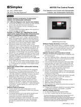
In case of one contact supervising
No. Item Specification
1 Rated voltage range of SLC input power (S+,S-) 22.0 to 24.0V
2 Maximum SLC 24 VDC standby current (S+,S-) 250μA
3 Maximum SLC 24 VDC alarm current (S+,S-) 1mA
4 IDC input circuit wiring style NFPA Class A (Style D)
5 Maximum wiring resistance of IDC 100Ω
6 Maximum wiring capacitance of IDC 1μF
7 Operating temperature range 32 to 120F (0 to 49C)
8 Operating humidity range 0 to 93% (non-condensing)
9 Maximum no. of module per loop 127 units
10 Address per module 1 Address
11 Dimensions 4.17”(106mm) (H) × 4.17”(106mm) (W)
× 1.14”(29mm) (D)
12 Applicable electrical box for installation 2-1/2”(64mm)deep 2-gang box
Standard 4square box 1-1/2”(38mm)deep box
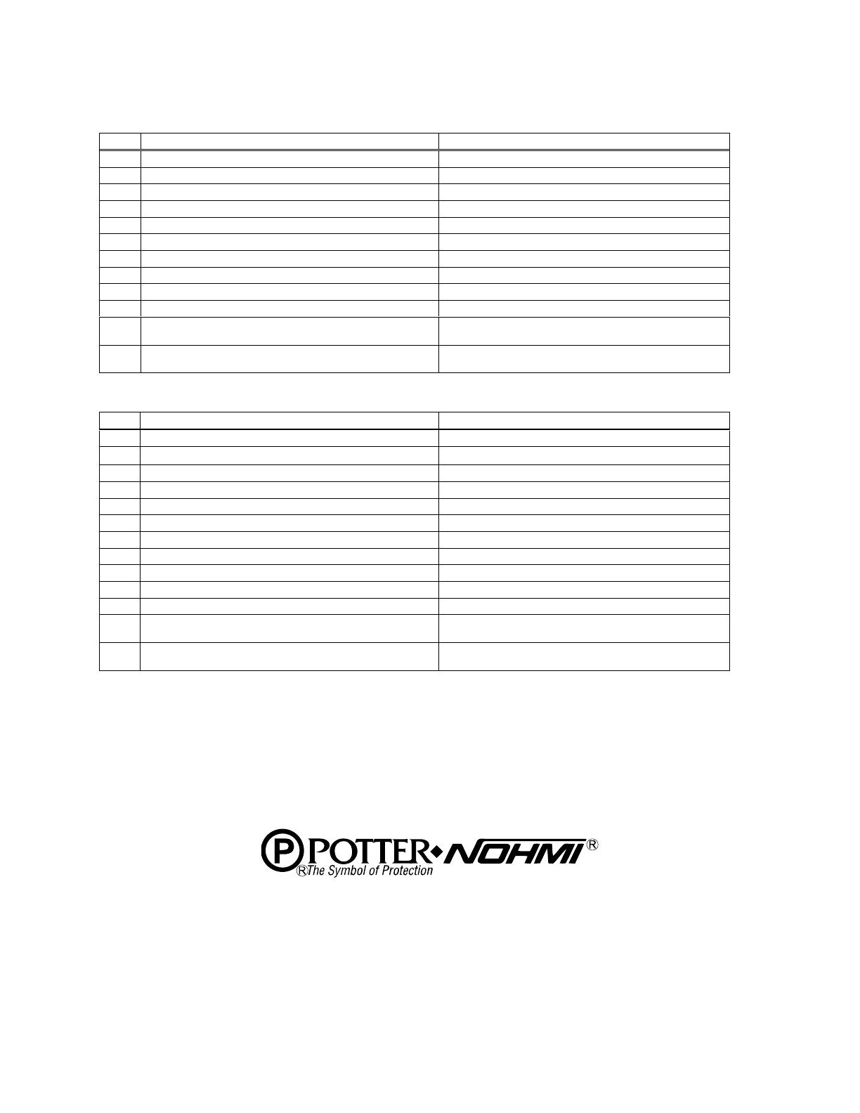
In case of two contacts supervising
No. Item Specification
1 Rated voltage range of SLC input power (S+,S-) 22.0 to 24.0V
2 Maximum SLC 24 VDC standby current (S+,S-) 250μA
3 Maximum SLC 24 VDC alarm current (S+,S-) 1mA
4 IDC input circuit wiring style NFPA Class B (Style B)
5 End-of-line resistor for IDC 5.1kΩ,1/2W
6 Maximum wiring resistance of IDC 100Ω
7 Maximum wiring capacitance of IDC F
8 Operating temperature range 32 to 120F (0 to 49C)
9 Operating humidity range 0 to 93% (non-condensing)
10 Maximum no. of module per loop 127 units
11 Address per module 2 Addresses
12 Dimensions 4.17”(106mm) (H) × 4.17”(106mm) (W)
× 1.14”(29mm) (D)
13 Applicable electrical box for installation 2-1/2”(64mm)deep 2-gang box
Standard 4square box 1-1/2”(38mm)deep box
These instructions do not purport to cover all the details or variations in the equipment described, nor provide
for every possible contingency to be met in connection with instillation, operation and maintenance.
Specifications subject to change without prior notification
For Technical Assistance contact Potter Electric Signal Company at 800-325-3936
Actual performance is based on proper application of the product by a qualified professional.
Should further information be desired or should particular problems arise, which are not covered sufficiently
for the purchaser's purpose, the matter should be referred to Nohmi or a distributor in your region.
Potter Electric Signal Company, LLC
1609 Park 370 Place, Hazelwood, MO 63042 USA
Telephon e: (866)956-1211
URL: http://www.pottersignal.com
  • Page 1 1
  • Page 2 2
  • Page 3 3
  • Page 4 4

Potter DCM-4 User manual

Category
Fire protection
Type
User manual

Potter DCM-4 is a dual contact module designed to supervise multiple contact points with unique addresses from a single device. It can be configured to monitor either one or two normally open contacts. In one contact mode, it employs Class A wiring methods. When monitoring two contacts, use Class B wiring. The DCM-4 is fully supervised and utilizes a single red LED to indicate its status: flashing for normal, constant on for activated contact, and off for open circuit. With a maximum of 13 points allowed to illuminate constantly, the LED will flash if additional devices are in alarm condition.

Ask a question and I''ll find the answer in the document

Finding information in a document is now easier with AI