Page is loading ...

SERIAL NUMBER (located on back of product):
PATENTS: U.S. 05971402 05/04/2021 – MSS40-AB
Phone: 800-669-1303 or 801-561-0303
Fax: 801-255-2312
e-mail: tre[email protected]
SS40
Surge Suppressor
Operation / Maintenance
Manual

SS40 SURGE OPERATION / MAINTENANCE MANUAL CONTENTS
CONTENTS
1 INSTALLATION ............................................................................................................ 3
1.1 UNPACKING ...................................................................................................... 3
1.2 LOCATING / MOUNTING SURGE ..................................................................... 3
1.2.a Mounted ................................................................................................. 4
1.2.b Inline ...................................................................................................... 5
2 MAINTENANCE ............................................................................................................ 6
2.1 RECOMMENDED SPARE PARTS .................................................................... 6
2.2 TOOLS ................................................................................................................ 6
2.3 PARTS ILLUSTRATION ..................................................................................... 6
2.4 PARTS LIST ....................................................................................................... 7
2.5 CLEAN-UP .......................................................................................................... 7
2.6 DISASSEMBLY .................................................................................................. 7
2.7 ASSEMBLY ........................................................................................................ 8
3 WARRANTY ................................................................................................................. 9

SS40 SURGE OPERATION / MAINTENANCE MANUAL PAGE 3
1 INSTALLATION
1.1 UNPACKING
After unpacking, the surge suppressor should be checked for any damage that
may have occurred during shipment. Damage should be reported to the carrier
immediately.
The following items should be included within the shipping container:
Qty
Item
Description
1
SS40
SS40 Surge Suppressor
1
MSS40
Operation/Maintenance Manual
1
Fitting
3/8” Male Branch Tee
2’
Tubing
3/8” PE Tubing
1
**
Seal, Port
**Dependent upon type of pump option selected.
1.2 LOCATING / MOUNTING SURGE
• Remove port plug from pump.
• Install new port seal.
• Hand tighten surge suppressor into port. Do not over tighten.
ATTENTION: Over-tightening adapter into pump will result in pump damage.

PAGE 4 SS40 SURGE OPERATION / MAINTENANCE MANUAL
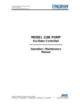
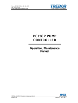
1.2.a Mounted
Figure 1-1
Pump
Assembled Height: IN (CM)
MODEL 110
11.03 (28.02)
MAGNUM 610
12.37 (31.43)
MAXIM 25
12.95 (32.89)
MAGNUM 620
12.63 (32.08)
NOTE: Install the branch tee in the pump air supply port to replace the pump air
connector fitting and then use the supplied tubing to connect between the pump
and the “SUP” port suppressor fitting.
NOTE: When mounted to a Maxim 25E/U pump, the SS40 requires it’s own
separate air supply line.


PAGE 6 SS40 SURGE OPERATION / MAINTENANCE MANUAL
2 MAINTENANCE
2.1 RECOMMENDED SPARE PARTS
KRSS40-00-A Spares Rebuild Kit, which includes:
Part No
Qty
Description
AT002
1
.020 Thick PTFE Diaphragms
AT013
1
Pilot Valve Assembly
2.2 TOOLS
The following tool kit is recommended as standard service equipment.
KTSS40-00-A Tool Kit, which includes:
Part No
Qty
Description
98003108
1
Torque Wrench, 30-150 Ft. Lb.
98003305
1
1/4” Drive Handle
T0129
1
Strap Wrench
T0146
1
3/4” Pin Tool
T0148
1
1/2” Pin Tool
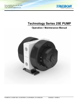
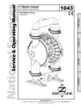
2.3 PARTS ILLUSTRATION

SS40 SURGE OPERATION / MAINTENANCE MANUAL PAGE 7
2.4 PARTS LIST
ILL
NO
PART NO
QTY
DESCRIPTION
MATERIAL
1
AT021
1
Union Nut
PP
2
98002915 or
98003335
2
3/4” Flare Nut (Inline Only) (PVDF) or
NUT;PFA;FLRLK;3/4T (PFA)
PP
3
AM084
1
Seal,1.380x.63x.02
PTFE
3a
J0100
1
Seal,.97x.38x.02
PTFE
3b
AW017
1
Seal,1.180x.55x.02
PTFE
4
AT004
1
Fluid Chamber, Inline
PTFE
4a
AT017
1
Fluid Chamber, 610/Maxim
PTFE
4b
AT012
1
Fluid Chamber, 110
PTFE
4c
AT015
1
Fluid Chamber, 620
PTFE
5
AT002
1
Diaphragm
PTFE
6
AT006
1
Push Plate
PTFE
7
AT005
1
Pilot Boss
PP
8
AT007
1
Shaft
PFA
9
AT013
1
Pilot Valve Assembly
PTFE / PFA
10
C0082
1
Seal
PTFE
11
AT003
1
Air Chamber
PP
12
98003396
1
3/8” Male Connector
PP
13
AT019
1
Mounting Bracket
PP
14
98003207
2
Screw
PP
2.5 CLEAN-UP
The SS40 Surge Suppressor may be flushed clean with either DI water or a rinse
tank for 10 to 15 minutes.
2.6 DISASSEMBLY
During the life of the Surge Suppressor it may be necessary to perform certain
preventative maintenance procedures to ensure its continued high performance.
This Section and Section 2.7 Assembly are provided for the user’s convenience
in disassembling and re-assembling the surge suppressor.
• Thoroughly clean and flush the suppressor and pump before disassembly if
possible using DI water.
• Disconnect suppressor air supply line from suppressor.
• Rotate suppressor CCW (counter-clockwise) to remove suppressor from
pump and place in containment bag.
• Decontaminate both exterior and fluid chamber of suppressor using DI water.
• Remove any air fittings from supply and exhaust ports of the suppressor
body.
• Clamp suppressor in vise to hold body with fluid connection pointing up.
• Using strap wrench and 1/2” torque wrench driver, remove union nut turning it
CCW to loosen.
• Remove union nut carefully. Watch threads for possible entrapment of spilled
chemical.
• Remove suppressor head noting clocked position of 1/16” diameter locating
mark on head for reassembly.
• Remove diaphragms for inspection.

PAGE 8 SS40 SURGE OPERATION / MAINTENANCE MANUAL
• Flush body with DI water and dry to remove any possible contamination.
• Connect suppressor supply port to 20-psig air supply and test pilot valve for
leakage and actuation. Replace if escaping air can be heard or valve will not
discharge when depressed.
• Insert small flat blade screwdriver in center hole of push plate to prevent shaft
from turning. Remove push plate by rotating it CCW.
• Remove pilot valve boss using 3/4” pin tool to rotate boss CCW.
• Disassemble pilot boss assembly and replace pilot assembly or other worn
parts.
• Check .020 diameter air bleed port in back wall of suppressor for possible
blockage.
NOTE: All polypropylene and PTFE parts, when disassembled, should be
thoroughly washed and free from acid residue for handling purposes.
2.7 ASSEMBLY
• Check that all parts are clean and dry.
• Use a new pair of protective gloves to prevent carry over contamination.
• Reverse disassembly procedure starting with reassembling pilot boss
assembly.
• Before reinstalling diaphragms, check diaphragms for white colored creases
or other signs of wear or damage. Replace if necessary.
• Complete reassembly by re-clocking 1/16” diameter mark in head to the
original position. (Failure to do so will result in air fitting misalignment after
mounting suppressor.)
• Retorque union nut using strap wrench and torque wrench to 65 ft-lbs.
• Reinstall suppressor on pump to hand tight plus 1/4 turn. If connection leaks,
increase an additional 1/8 turn only. If leaking cannot be stopped, remove
suppressor, replace disk seal and check mating surfaces for scratches or
depressions.

SS40 SURGE OPERATION / MAINTENANCE MANUAL PAGE 9
3 WARRANTY
SS40 SURGE SUPPRESSOR
TREBOR International, Inc. warrants to the purchaser of new equipment
manufactured by TREBOR to be free from defects in material and workmanship
when used for its intended purpose under normal operating conditions, and
maintained according to the Operation/Maintenance Manual.
TREBOR’s obligation under this warranty is limited to repairing or replacing, at
TREBOR’s option and at the TREBOR factory, any part or parts thereof which
shall, within 1 year after delivery thereof to the original purchaser, be
demonstrated to TREBOR’s satisfaction to have been defective. This warranty
may be transferred to subsequent owners. The warranty period is based on the
original ship date from the factory. All warranty related freight costs shall be
borne by the customer.
Excessive wear to pump components caused by pumping abrasive solutions or
chemicals, as well as damage caused by ingesting foreign objects shall not be
covered by this warranty.
This warranty shall not apply to any equipment which, in the judgment of
TREBOR, shall have been repaired or altered outside TREBOR’s factory in any
way, so as to affect its performance or reliability; subjected to misuse, negligence
or accident; or used other than in accordance with TREBOR’s printed
instructions.
There are no terms, conditions or warranties, expressed, implied or
statutory, of merchantability, fitness, capacity, or otherwise, of the goods
ordered, other than, or different from, the warranty set forth above. This
warranty takes precedence over any other warranty, expressed or implied.
TREBOR neither assumes, nor authorizes any other party to assume for it, any
liability in connection with said equipment except as set forth above.
/