innovair TC12C2DWB1 User manual
- Category
- Split-system air conditioners
- Type
- User manual
This manual is also suitable for

FAN COIL
USER MANUAL
TC18C2DWB1
TC24C2DWB1
TC37C2DWB1
TC48C2DWB1
TC60C2DWB1
©2015 Innovair Corporation. All Rights Reserved.
www.innovair.com

Duct Type
6 Duct Type
1. Features................................................................................7
2. Dimensions ......................................................................8
3. Service Space...................................................................9
4. Wiring Diagrams ............................................................10
5. Capacity Tables..............................................................11
6. Capacity Correction Factors.........................................12
7. Static Pressure...............................................................13
8. Electric Characteristics.................................................14
9. Sound Levels .................................................................15
10. Accessories..................................................................16
11. The Specification of Power .........................................17
12. Field Wiring..................................................................19
©2015 Innovair Corporation. All Rights Reserved.
www.innovair.com

Features
Duct Type 7
1. Features
1. Optional accessories
2. Two air intake methods: from below or back
Air inlet from back standard and from bottom optional
Because the size of the plate from bottom and flange from back is same,it
s easy to change the air inlet
from back to bottom by installer.
Just remove the plate from bottom and flange from back,then exchange the location and install them again
3. Water pump is optional and the maintenance is very easy
The pump can be took down very easy by screwed off the four screws.
Front boar Panel Canvas air passage
Filter
©2015 Innovair Corporation. All Rights Reserved.
www.innovair.com

Service Space
8 Duct Type
2. Dimensions
Outline
dimension(mm) Air outlet o
pening size Air return
opening size Size of outline dimension mounted
plug
Capacity
(KBtu) A B C D E
F G
H I J K
L M
12 700
210
635
570
65
713
35
119
815
200
80
960 350
18 920
210
635
570
65
713
35
119
815
200
80
960 350
24 920
270
635
570
65
713
35
179
815
260
20
960 350
30/36 1140
270
775
710
65
933
35
179
1035
260
20
1180 490
48/60 1200
300
865
800
80
968
40
204
1094
288
45
1240 500
©2015 Innovair Corporation. All Rights Reserved.
www.innovair.com

Dimensions
Duct Type 9
3. Service Space
Ensure enough space required for installation and maintenance.
©2015 Innovair Corporation. All Rights Reserved.
www.innovair.com

Wiring Diagrams
10 Duct Type
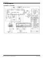
4. Wiring Diagrams
TC18C2DWB1 TC24C2DWB1
©2015 Innovair Corporation. All Rights Reserved.
www.innovair.com

Capacity Tables
Duct Type 11
5. Capacity Tables
6.1 Cooling Capacity
TC18C2DWB1
Cooling Outdoor conditions (DB)
Indoor Conditions (kW) 21ºC 28ºC 35ºC 43ºC
TC 5.46 5.19 4.93 4.72
SC 4.04 4.00 3.94 3.96
21/15ºC DB/WB Input 1.60 1.74 1.81 1.87
TC 5.62 5.35 5.09 4.77
SC 4.21 4.18 4.12 4.01
24/17ºC DB/WB Input 1.70 1.81 1.89 1.99
TC 5.72 5.46 5.30 4.93
SC 4.24 4.20 4.13 4.04
27/19ºC DB/WB Input 1.74 1.83 1.93 2.03
TC 5.83 5.62 5.51 5.09
SC 4.96 4.89 4.85 4.73
32/23ºC DB/WB Input 1.81 1.89 2.03 2.10
TC24C2DWB1
Cooling Outdoor conditions (DB)
Indoor Conditions (kW) 21ºC 28ºC 35ºC 43ºC
TC 7.31 6.96 6.60 6.32
SC 5.41 5.36 5.28 5.31
21/15ºC DB/WB Input 2.15 2.33 2.43 2.51
TC 7.53 7.17 6.82 6.39
SC 5.64 5.59 5.52 5.37
24/17ºC DB/WB Input 2.28 2.43 2.54 2.67
TC 7.67 7.31 7.10 6.60
SC 5.67 5.63 5.54 5.41
27/19ºC DB/WB Input 2.33 2.46 2.59 2.72
TC 7.81 7.53 7.38 6.82
SC 6.64 6.55 6.50 6.34
32/23ºC DB/WB Input 2.43 2.54 2.72 2.82
Remark:
TC: Total capacity ; kW
SC: Sensible heat capacity ; kW
Input: Input power; kW
©2015 Innovair Corporation. All Rights Reserved.
www.innovair.com

Capacity Tables
12 Duct Type
6. Capacity Correction Factors
1. Rate of change in cooling capacity
2. Rate of change in heating capacity
0
10
20
30
40
50
-10
-20
-30 20 30
10 40 50 60 70 80
Pipe equivalent length L(m)
100%
Outdoor unit
99%
98%
97%
©2015 Innovair Corporation. All Rights Reserved.
www.innovair.com

Static Pressure
Duct Type 13
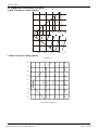
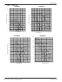
7. Static Pressure
12,000Btu/h 18,000Btu/h
Super high speed
0900
600
500
Mid speed
High speed
External static pressure (Pa)
3
Air volume(m /h)
Pa
90
80
70
60
50
40
30
20
10
Low speed
300 400 700 800
Super high speed
500400300
200
Low speed
10
20
30
40
50
60
70
80
90
Pa
600 700 800 900 1000 1100
Air volume(m /h)
3
External static pressure (Pa)
High speed
Mid speed
1200
24,000Btu/h 36,000Btu/h
Super high speed
14001300
Low speed
10
20
30
40
50
60
70
80
90
Pa
800 900 1000 1100
Air volume(m /h)
3
External static pressure (Pa)
High speed
Mid speed
1200 1500
700
Pa
Super high speed
2000
1800
1200
36K
Mid speed
High speed
3
Air volume(m /h)
1100
90
80
70
60
50
40
30
20
10
Low speed
1400 1600 2200 2400
©2015 Innovair Corporation. All Rights Reserved.
www.innovair.com

Static Pressure
14 Duct Type
48,000Btu/h 60,000Btu/h
120
110
Super high speed
100
Pa
2500
2200
1300
48K
Mid speed
High speed
External static pressure (Pa)
3
Air volume(m /h)
1000
90
80
70
60
50
40
30
20
10
Low speed
1600 1900 2800 3100
120
110
Super high speed
3400
100
3100
2800
19001600
Low speed
10
20
30
40
50
60
70
80
90
Pa
1000 Air volume(m /h)
3
External static pressure (Pa)
High speed
Mid speed
1300 2200 2500
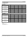
8. Electric Characteristics
Indoor Units Power Supply
Model Hz Voltage
Min. Max. MCA MFA
TC18C2DWB1 60 220-230V 198V 242V 0.8 16
TC24C2DWB1 60 220-230V 198V 242V 0.91 16
Remark:
MCA: Min. Current Amps. (A)
MFA: Max. Fuse Amps. (A)
©2015 Innovair Corporation. All Rights Reserved.
www.innovair.com

Static Pressure
Duct Type 15
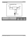
9. Sound Levels
Suction
Discharge
Microphone
1.4m
Concealed Duct Type
DuctDuct
Noise level dB(A)
Model H M L
TC18C2DWB1 44 31 26
TC24C2DWB1 44 35 32
©2015 Innovair Corporation. All Rights Reserved.
www.innovair.com

Sound Levels
16 Duct Type
10. Accessories
Name Quantity Shape Remark
Soundproof / insulation sheath 2
Binding tape 1
Seal sponge 1
Orifice 1 Only For R22,Cooling/Heating Unit
Except Model 12
Drain joint 1
Seal ring 1
Wire controller 1
Owner‘s manual 1
Installation manual 1
©2015 Innovair Corporation. All Rights Reserved.
www.innovair.com

Field Wiring
Duct Type 19
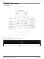
12. Field Wiring
TC18C2DWB1 TC24C2DWB1
©2015 Innovair Corporation. All Rights Reserved.
www.innovair.com

Installation MLCAC-UTSM-2008-11
20 Installation
Installation
1.Precaution on Installation.........................................21
2.Vacuum Dry and Leakage Checking........................22
3.Additional Refrigerant Charge .................................24
4.Water Drainage..........................................................25
5.Insulation Work .........................................................28
6.Wiring.........................................................................29
7.Test Operation...........................................................30
©2015 Innovair Corporation. All Rights Reserved.
www.innovair.com

Precaution on Installation
Installation 21
1. Precaution on Installation
1). Measure the necessary length of the connecting pipe, and make it by the following way.
a. Connect the indoor unit at first, then the outdoor unit.
Bend the tubing in proper way. Do not harm them.
Specially Notice the pipe length/height/dimension of each capacity.
Maximum pipe length
Model Max. Length Max. Elevation
12,000Btu/h 15m 8m
18,000Btu/h ~24,000Btu/h 30m 10m
30,000Btu/h ~60,000Btu/h 30m 20m
Piping sizes Model Liquid(mm) Gas(mm)
12,000Btu/h~18,000Btu/h 6.4 12.7
24,000Btu/h 9.5 15.9
36,000(48,000)(60,000)Btu/h 9.5 19
CAUTIONS
Daub the surfaces of the flare pipe and the joint nuts with frozen oil, and wrench it for 3~4 rounds
With hands before fasten the flare nuts.
Be sure to use two wrenches simultaneously when you connect or disconnect the pipes.
Pipe gauge Tightening torque Flare dimension A
Min (mm) Max Flare shape
6.4 15
16N.m
(153 163 kgf.cm) 8.3 8.7
9.5 25
26N.m
(255 265kgf.cm) 12.0 12.4
12.7 35
36N.m
(357 367kgf.cm) 15.4 15.8
15.9 45
47N.m
(459 480 kgf.cm) 18.6 19.1
19.1 65
67N.m
(663 684kgf.cm) 22.9 23.3
b. The stop value of the outdoor unit should be closed absolutely (as original state). Every time you connect it, first loosen the nuts at the part
of stop value, then connect the flare pipe immediately (in 5 minutes). If the nuts have been loosened for a long time, dusts and other
impurities may enter the pipe system and may cause malfunction later. So please expel the air out of the pipe with refrigerant before
connection.
c. Expel the air after connecting the refrigerant pipe with the indoor unit and the outdoor unit. Then fasten the nuts at the repair-points.
2) Locate The Pipe
a. Drill a hole in the wall (suitable just for the size of the wall conduit), then set on the fittings such as the wall conduit and its cover.
b. Bind the connecting pipe and the cables together tightly with binding tapes. Do not let air in, which will cause water leakage by
condensation.
c. Pass the bound connecting pipe through the wall conduit from outside. Be careful of the pipe allocation to do no damage to the tubing.
3) Connect the pipes.
4) Then, open the stem of stop values of the outdoor unit to make the refrigerant pipe connecting the indoor unit with the outdoor unit in
fluent flow.
5) Be sure of no leakage by checking it with leak detector or soap water.
6) Cover the joint of the connecting pipe to the indoor unit with the soundproof / insulating sheath (fittings), and bind it well with the tapes to
prevent leakage.
©2015 Innovair Corporation. All Rights Reserved.
www.innovair.com

Vacuum Dry and Leakage Checking MLCAC-UTSM-2010-06
22 Installation
2. Vacuum Dry and Leakage Checking
1) Vacuum Dry: use vacuum pump to change the moisture (liquid) into steam (gas) in the pipe and discharge it out of the pipe to make the
pipe dry. Under one atmospheric pressure, the boiling point of water(steam temperature) is 100 . Use vacuum pump to make the
pressure in the pipe near vacuum state, the boiling point of water falls relatively. When it falls under outdoor temperature, the moisture in
the pipe will be vaporized.
Necessary
vacuum
degree
2) Vacuum dry procedure
There are two methods of vacuum dry due to different construction environment: common vacuum dry, special vacuum dry.
. Common vacuum dry procedure
Vacuum dry (for the first time)---connect the all-purpose detector to the inlet of liquid pipe and gas pipe, and run the vacuum pump more
than two hours (the vacuum pump should be below -755mmHg)
If the pump can’t achieve below -755mmHg after pumping 2 hours, moisture or leakage point will still exist in the pipe. At this time, it
should be pumped 1 hour more.
If the pump can’t achieve -755mmHg after pumping 3 hours, please check if there are some leakage points.
Vacuum placement test: place 1 hour when it achieves -755mmHg, pass if the vacuum watch shows no rising. If it rises, it shows there’s
moisture or leakage point.
Vacuuming from liquid pipe and gas pipe at the same time.
Sketch map of common vacuum dry procedure.
©2015 Innovair Corporation. All Rights Reserved.
www.innovair.com

Vacuum Dry and Leakage Checking
Installation 23
. Special vacuum dry procedure
This vacuum dry method is used in the following conditions:
There’s moisture when flushing the refrigerant pipe.
Rainwater may enter into the pipe.
Vacuum dry for the first time ······ 2h pumping
. Vacuum destroy for the second time ······ Fill nitrogen to 0.5Kgf/cm2
Because nitrogen is for drying gas, it has vacuum drying effect during vacuum destroy. But if the moisture is
too much, this method can’t dry thoroughly. So, please pay more attention to prevent water entering and
forming condensation water.
. Vacuum dry for the second time······1h pumping
Determinant: Pass if achieving below -755mmHg. If -755mmHg can’t be achieved in 2h, repeat procedure
and .
. Vacuum placing test ······ 1h
. Sketch map of special vacuum dry procedure
©2015 Innovair Corporation. All Rights Reserved.
www.innovair.com

Additional Refrigerant Charge MLCAC-UTSM-2010-06
24 Installation
3. Additional Refrigerant Charge
Caution
a) Refrigerant cannot be charged until field wiring has been completed.
b) Refrigerant may only be charged after performing the leak test and the vacuum pumping.
c) When charging a system, care shall be taken that its maximum permissible charge is never exceeded,
in view of the danger of liquid hammer.
d) Charging with an unsuitable substance may cause explosions and accidents, so always ensure that the
appropriate refrigerant is charged.
e) Refrigerant containers shall be opened slowly.
f) Always use protective gloves and protect your eyes when charging refrigerant.
The outdoor unit is factory charged with refrigerant. Calculate the added refrigerant according to the
diameter and the length of the liquid side pipe of the outdoor unit/indoor unit.
For 12kBtu/h (outdoor unit throttle)
R(g) D(mm)
L(m) 6.4
Less than 5m (One-way) —
Added Refrigerant When
Over 5m(One-way) 15g/m×L
For 18, 24, 36, 48, 60kBtu/h (indoor unit throttle)
R(g)
D(mm)
L(m)
6.4 9.5 12.7
Less than 5m (One-way) — — —
Added Refrigerant When
Over 5m(One-way) 30g/m×(L-5) 65g/m×(L-5) 115g/m×(L-5)
Remark:
R (g): Additional refrigerant to be charged
L (m): The length of the refrigerant pipe (one-way)
D (mm): Liquid side piping diameter
©2015 Innovair Corporation. All Rights Reserved.
www.innovair.com

Water Drainage
Installation 25
4. Water Drainage
4.1 Gradient and Supporting
1). Keep the drainpipe sloping downwards at a gradient of at least 1/50. Keep the drainpipe as short as possible and eliminate the air bubble.
2). The horizontal drainpipe should be short. When the pipe is too long, a prop stand must be installed to keep the gradient of 1/50 and
prevent bending. Refer to the following table for the specification of the prop stand.
Diameter Distance between the prop stands
Hard PVC pipe 25~40mm 1.5~2m
3). Precautions
The diameter of drainpipe should meet the drainage requirement at least.
the drainpipe should be heat-insulated to prevent atomization.
Drainpipe should be installed before installing indoor unit. After powering on, there is some water in water-receiver plate. Please check if the
drain pump can operate correctly.
All connection should be firm.
Wipe color on PVC pipe to note connection.
Climbing, horizontal and bending conditions are prohibited.
The dimension of drainpipe can’t less than the connecting dimension of indoor drainpipe.
Heat-insulation should be done well to prevent condensation.
Indoor units with different drainage type can’t share one convergent drainpipe.
4.2 Drainpipe Trap
1). If the pressure at the connection of the drainpipe is negative, it needs to design drainpipe trap.
2). Every indoor unit needs one drainpipe trap.
3). A plug should be designed to do cleaning.
50cm 50cm
4.3 Upwards drainage (drain pump)
For Four-way cassette(compact)
©2015 Innovair Corporation. All Rights Reserved.
www.innovair.com

Water Drainage
26 Installation
For Four-way cassette
4.4 Convergent drainage
1). The number of indoor units should be as small as possible to prevent the traverse main pipe overlong.
2). Indoor unit with drain pump and indoor unit without drain pump should be in different drainage system.
3). Selecting the diameter
Number of connecting indoor units Calculate drainage volume Select the diameter
Calculate allowed volume =Total cooling capacity of indoor units (HP)×2 (l/ hr)
Allowed volume(lean 1/50) (l/ hr) I.D. (mm) Thick
Hard PVC 14
25 3.0
Hard PVC 14
88 30 3.5
Hard PVC 88
334 40 4.0
Hard PVC 175
334 50 4.5
Hard PVC 334
80 6.0
4.5 Drainage test
1). Drainage without drain pump
After finishing drainpipe installation, pour some water into the water receiver plate to check if the water flows smoothly.
2). Drainage with drain pump
Poke the Water Level Switch, remove the cover, use water pipe to pour 2000ml water into the water receipt plate through the water
inlet.
Turn on the power to Cooling operation. Check the pump’s operation and switch on the Water Level Switc
h. Check the pump’s sound
and look into the transparent hard pipe in the outlet at the same time to check if the water can discharge normally.
©2015 Innovair Corporation. All Rights Reserved.
www.innovair.com
Page is loading ...
Page is loading ...
Page is loading ...
Page is loading ...
Page is loading ...
Page is loading ...
Page is loading ...
Page is loading ...
Page is loading ...
Page is loading ...
-
 1
1
-
 2
2
-
 3
3
-
 4
4
-
 5
5
-
 6
6
-
 7
7
-
 8
8
-
 9
9
-
 10
10
-
 11
11
-
 12
12
-
 13
13
-
 14
14
-
 15
15
-
 16
16
-
 17
17
-
 18
18
-
 19
19
-
 20
20
-
 21
21
-
 22
22
-
 23
23
-
 24
24
-
 25
25
-
 26
26
-
 27
27
-
 28
28
-
 29
29
-
 30
30


innovair TC12C2DWB1 User manual
- Category
- Split-system air conditioners
- Type
- User manual
- This manual is also suitable for
Ask a question and I''ll find the answer in the document
Finding information in a document is now easier with AI
Related papers
-
innovair TC12C2DWB1 Installation guide
-
-
-
-
-
-
-
-
-
Other documents
-
Dometic MX1200C User manual
-
 Sakata SIB-60DAV User manual
-
Center 340022 User guide
-
System Sensor Innovair flex 2D51 User manual
-
Klimaire KSIL048-H216-OC User manual
-
 Kaisai KCD-18HRFN1-QRC4 User manual
-
-
-
 North American HVAC MOC-12HFN1-MV0W User manual
-
 MDV MDTC-96HWN1 Technical & Service Manual


