Samsung DMR77LHB/XAC User manual
- Category
- Dishwashers
- Type
- User manual

DISHWASHER
Model Name :DMR78 Series
DMR77 Series
DMR57 Series
SERVICEManual
DISHWASHER CONTENTS
Refer to the service manual in the GSPN (see the rear cover) for the more information.
Safety Instructions1.
Features and Specications2.
Disassembly and 3.
Reassembly
Troubleshooting4.
Exploded Views and 5.
Parts List
PCB Diagram6.
Wiring Diagram7.
Schematic Diagram8.
Reference9.
Model Code : DMR78AHS/XAA DMR78AHS/XAC
DMR78AHB/XAA DMR78AHB/XAC
DMR78AHW/XAA DMR78AHW/XAC
DMR77LHS/XAA DMR77LHS/XAC
DMR77LHB/XAA DMR77LHB/XAC
DMR77LHW/XAA DMR77LHW/XAC
DMR57LFS/XAA DMR57LFS/XAC
DMR57LFB/XAA DMR57LFB/XAC
DMR57LFW/XAA DMR57LFW/XAC

Contents
The issues of changing.................................................................................................................4
1. Safety Instructions .................................................................................................................1-1
1-1. Safety Instructions for Service Engineers .......................................................................................................1-1
2. Features and Specications ..................................................................................................2-1
2-1. Features .........................................................................................................................................................2-1
2-2. Specications .................................................................................................................................................2-2
2-3. Comparing Specications with Existing Models .............................................................................................2-3
2-4. Options Specications ....................................................................................................................................2-5
3. Disassembly and Reassembly ..............................................................................................3-1
3-1. Tools for Removal and Reassembly ...............................................................................................................3-1
3-2. Standard Disassembly Drawings ....................................................................................................................3-2
3-3. Checkpoints after Finishing a Service ..........................................................................................................3-23
4. Troubleshooting .....................................................................................................................4-1
4-1. Changed Components ....................................................................................................................................4-1
4-2. Service Inspection Mode ................................................................................................................................4-2
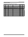
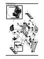
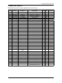
5. Exploded Views and Parts List ..............................................................................................5-1
5-1. MAIN (DMR77, DMR78) .................................................................................................................................5-2
5-2. ASSY-DOOR (DMR77, DMR78) .....................................................................................................................5-4
5-3. ASSY-TUB (DMR77, DMR78) ........................................................................................................................5-6
5-4. ASSY-BASE (DMR77, DMR78) ......................................................................................................................5-8
5-5. ASSY-SUMP (DMR77, DMR78) ...................................................................................................................5-10
5-6. ASSY-CASE (DMR77, DMR78) ....................................................................................................................5-12
5-7. MAIN (DMR57) .............................................................................................................................................5-14
5-8. ASSY-DOOR (DMR57) .................................................................................................................................5-16
5-9. ASSY-TUB (DMR57) .....................................................................................................................................5-18
5-10. ASSY-BASE (DMR57) ................................................................................................................................5-20
5-11. ASSY-SUMP (DMR57) ................................................................................................................................5-22
5-12. ASSY-CASE (DMR57) ................................................................................................................................5-24
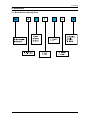
6. PCB Diagram.........................................................................................................................6-1
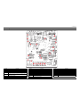
6-1. Old PBA - Main PCB .......................................................................................................................................6-1
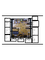
6-2. New PBA- Main PCB ......................................................................................................................................6-2
6-3.Old PBA - Detailed Specications and Descriptions for Connectors and Relay Terminals (MAIN PBA) .........6-3
6-4. New PBA- Detailed Specications and Descriptions for Connectors and Relay Terminals (MAIN PBA) ......6-4
6-5. Detailed Specications and Descriptions for Connectors (TOUCH 7KEY - DMR77, DMR78) .......................6-5
6-6. Detailed Specications and Descriptions for Connectors (TOUCH 7KEY - DMR57) .....................................6-6
6-7. Detailed Specications and Descriptions for Connectors (TOUCH 3KEY - DMR77,DMR78) ........................6-7
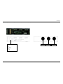
6-8. Detailed Specications and Descriptions for Connectors (DISPLAY LED - TOP - DMR77, DMR78 (DD07-00008A,
8B)) .......................................................................................................................................................................6-8

6-9. Detailed Specications and Descriptions for Connectors (DISPLAY LED - FRONT - DMR77, DMR78 (DD07-
00009A, 9B)) ..........................................................................................................................................................6-8
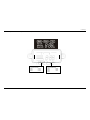
6-10. Detailed Specications and Descriptions for Connectors (DISPLAY LED - FRONT - DMR57) ....................6-9
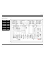
7. Wiring Diagram ......................................................................................................................7-1
7-1. Old Wiring Diagram (DMR77/78) ....................................................................................................................7-1
7-2. Old Wiring Diagram (DMR57) .........................................................................................................................7-2
7-3. New PBA - Wiring Diagram (DMR78, DMR77 , DMR57) ...............................................................................7-3
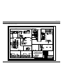
8. Schematic Diagram ...............................................................................................................8-1
8-1. MAIN CONTROL (DMR78, DMR77 , DMR57) ...............................................................................................8-1
8-3. TOUCH KEY (7KEY - DMR77, DMR78) .........................................................................................................8-2
8-4. TOUCH KEY (3KEY - DMR77, DMR78) .........................................................................................................8-3
8-5. TOUCH KEY (7KEY - DMR57) .......................................................................................................................8-4
9. Reference ..............................................................................................................................9-1
9-1. Model Number Naming Rules ........................................................................................................................9-1
9-2. Terminology ....................................................................................................................................................9-2

The issues of changing
Date Contents
2008. 12. 01
Add the Model(DMR78) ሪ
Change the Service inspection mode entry method. (Page 4-1)
Add the Assy-install kit for SVC parts (Page 2-5) ሪ

1-1
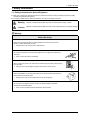
1. Safety Instructions
1. Safety Instructions
1-1. Safety Instructions for Service Engineers
Make sure to observe the following instructions to operate the product correctly and safely and prevent possible ሪ
accidents and hazards while servicing.
Two types of safety symbols, Warning and Caution, are used in the safety instructions. ሪ
Warning Hazards or unsafe practices that may result in severe personal injury or death.
Caution Hazards or unsafe practices that may result in minor personal injury or property damage.
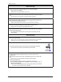
Warning
Before Servicing
(When servicing electrical parts or harnesses) Make sure to disconnect the circuit ࣃ
breaker or power cable before servicing.
Failing to do so may result in a risk of electric shock. ➢
Do not allow consumers to connect several appliances to a single power outlet at the
ࣃ
same time.
There is a risk of re due to overheating. ➢
When removing the power cord, make sure to hold the power plug when pulling the plug ࣃ
from the outlet.
Failing to do so may damage the plug and result in re or electric shock. ➢
When the dishwasher is not being used, make sure to disconnect the circuit breaker or ࣃ
power cable from the power outlet.
Failing to do so may result in electric shock or re due to lightning. ➢
Do not place or use gasoline, thinners, alcohol, or other ammable or explosive ࣃ
substances near the dishwasher.
There is a risk of explosion and re caused from electric sparks. ➢

1-2
1. Safety Instructions
While Servicing
Check if the power cable is damaged, attened, cut or otherwise degraded. ࣃ
If faulty, replace it immediately. ➢
Failing to do so may result in electric shock or re.
Completely remove any dust or foreign material from the housing, wiring and connection
ࣃ
parts.
This will prevent a risk of re due to tracking and shorts in advance. ➢
When connecting wires, make sure to connect them using the relevant connectors and
ࣃ
check that they are completely connected.
If tape is used instead of the connectors, it may cause re due to tracking. ➢
Make sure to discharge the PBA power terminals before starting the service.
ࣃ
Failing to do so may result in a high voltage electric shock. ➢
When replacing the heater, make sure to fasten the holder heater after ensuring that it is
ࣃ
inserted into the bracket-heater.
If not inserted into the bracket-heater, it touches the tub and causes noise and ➢
electric leakage.
After Servicing
Check for any water leakage. ࣃ
Perform a test run for the dishwasher using the standard(normal) cycle and check ➢
whether there is any water leakage through the oor section or the pipes.
Do not allow consumers to repair or service any part of the dishwasher themselves.
ࣃ
This may result in personal injury and shorten the product lifetime. ➢
If it seems that grounding is needed due to water or moisture, make sure to run ࣃ
grounding wires.
(Check the grounding of the power outlet, and additionally ground it to a metallic water
pipe.)
Failing to do so may result in electric shock due to electric leakage. ➢
[Running a grounding wire]
- Twist a grounding wire (copper wire) two or three times around the tap.
- If you connect the grounding wire to a copperplate, bury it 75 cm under the earth in a
place with a lot of moisture.
Do not connect the grounding wire to a gas pipe, plastic water pipe or telephone
wire. There is a risk of electric shock or explosion.

1-3
1. Safety Instructions
Caution
Before Servicing
Do not sprinkle water onto the dishwasher directly when cleaning it. ࣃ
This may result in electric shock or re, and may shorten the product lifetime. ➢
Do not place any containers with water on the dishwasher.
ࣃ
If the water is spilled, it may result in electric shock or re. This will also shorten the ➢
product lifetime.
Do not install the dishwasher in a location exposed to snow or rain. ࣃ
This may result in electric shock or re, and shorten the product lifetime. ➢
Do not press a control button using a sharp tool or object. ࣃ
This may result in electric shock or damage to the product. ➢
During Servicing
When wiring a harness, make sure to seal it completely so no liquid can enter. ࣃ
Make sure that they do not break when force is exerted. ➢
Check if there is any residue that shows that liquid entered the electric parts or
ࣃ
harnesses.
If any liquid has entered into a part, replace it or completely remove any remaining ➢
moisture from it.
If you need to place the dishwasher on its back for servicing purposes, place a support(s)
ࣃ
on the oor and lay it down carefully so the back is on the oor.
Do not lay it down on its front or side. This may result in scratches to the surface or ➢
damage to the parts.

1-4
1. Safety Instructions
After Servicing
Check the assembled status of the parts. ࣃ
They must be the same as before servicing. ➢
Check the insulation resistance.
ࣃ
Disconnect the circuit breaker or power cable from the power outlet and measure ➢
the insulation resistance between the power wires and the grounding wire of the
dishwasher. The value must be greater than 10MΩ when measured with a 500V DC
Megger.
Check whether the product is level with the oor. Check if there are any deformations in
ࣃ
the sink. Check that the dishwasher is rmly installed to the sink.
Vibrations can shorten the lifetime of the product. ➢

2-1
2. Features and Specications
2. Features and Specications
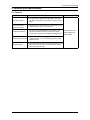
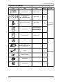
2-1. Features
Features Description Remarks
Extra large capacity
The upper rack is slanted for larger dishes. The space ሪ
has been maximized to accommodate a variety of dish
sizes.
Applicable to all of the
DMR77, DMR78 and
DMR57 models
Elegant design with
digital touch sensors
Digital touch sensors are used in the control panel for more ሪ
simple operation, with a touch of elegance.
Increased convenience
The smart auto cycle determines the level of soil on the ሪ
dishes and initiates the optimal cycle using this feature
saving water, energy and time. (DMR77 and DMR78 only)
Extremely quiet operation
Efcient noise control technology is used for the quietest ሪ
possible operation. Your new Samsung dishwasher will be
quieter than ever.
Self-cleaning lter
Cleaning the lter yourself is a thing of the past! This product ሪ
keeps food waste internally while operating, then drains it
automatically with the water.

2-2
2. Features and Specications
2-2. Specications
Wash capacity 14 place settings
Type Dishwasher
Model
DMR78AHS, DMR78AHB, DMR78AHW
DMR 77LHS, DMR 77LHB, DMR 77LHW
DMR 57LFS, DMR 57LFB, DMR 57LFW
Power Single-phased alternating current of 60Hz, 15A at 120V
Used water pressure 20 ~ 120 psi (140 ~ 830 kPa)
Wash type Rotating nozzle spray
Dry type Condensed dry system
Power usage Main Motor : 165W / Heater : 1100W
Standard amount of used water 3.9~7.7 gallon(14.8~29ℓ), Normal Cycle
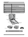
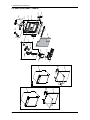
Size (W×D×H) 23 ⅞” x 24 ¾” x 33 ⅞” inch (605 x 622 x 860 mm )
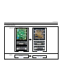
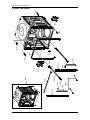
Above images might differ in the dishwasher models.
Drain hose
Air brake
Base
Dispenser
Door
Lower nozzle
Vapor vent cover
Control panel
Middle nozzle
Upper rack Lower rack Cutlery basket

2-3
2. Features and Specications
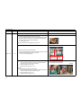
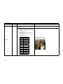
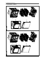
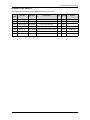
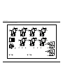
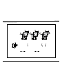
2-3. Comparing Specications with Existing Models
Model
BEST MODEL BETTER MODEL GGH DESIGN
DMR 77LHS DMR 77LHB DMR 77LHW DMR 57LFS DMR 57LFB DMR 57LFW DMR78AHS
Photo
Design Specications
Panel
Control Black Black Black Silver Black White Black
Frame
Front STS Black White STS Black White STS
Handle Aluminum Black White X X X STS
Cover
Handle XXXCr Black Cr X
Cover
Front L Silver Black White Silver Black White Silver
Functional Specications

2-4
2. Features and Specications
Model
BEST MODEL BETTER MODEL GGH DESIGN
DMR 77LHS DMR 77LHB DMR 77LHW DMR 57LFS DMR 57LFB DMR 57LFW DMR78AHS
Functional Specications
Soil
Detection
Sensors
OOOOOOO
Basket
Height
Adjustment
One-touch One-touch One-touch 2-stage 2-stage 2-stage One-touch
Half Load OOOX X X O
Child Lock OOOOOOO
Smart Auto OOOX X X O
Sanitize OOOOOOO
Leakage
Sensor OOOOOOO
Fan Motor OOOOOOO
Delay start OOOOOOO
Quick cycle OOOXXXO

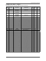
2-4. Options Specications
Photo Item Code Quantity Remarks
Bracket-install DD61-00176A 2
Provided with
the dishwasher
Assy-install kit for Top
mounting
(Bracket-install + Screw)
DD94-01002A 2+2
Screw for side mounting DD81-01266A 2
User Manual
DD68-00036A(DMR78)
DD68-00018A(DMR77)
DD68-00026A (DMR57)
1
Installation Guide DD68-00027A 1
Elbow - 1
Sold separately
Water Supply Line
(Flexible STS supply line is
recommend)
- 1
Air Gap - 1
Rubber Connector -1
Hose Clamp -1
Strain Relief -1
2-5
2. Features and Specications

2-6
2. Features and Specications
Memo

3-1
3. Disassembly and Reassembly
3. Disassembly and Reassembly
3-1. Tools for Removal and Reassembly
Tool image
No. Tool Type Remarks
➊Adjustable Wrench
➋Open-end Wrench 1-7/16” Leg
➌Vice pliers
➍Others
(screwdriver, nipper, long nose pliers)
Common tools for servicing
Screwdriver - Philips, at, Torx T20
* Preparation for parts replacement
1. Take out the residual water inside the product.
(Drain the water by operating the drain pump)
2. Close the water supply valve.
3. Turn off the power & disconnect power cable.
You must turn off the circuit breaker connected to the product.
4. Pull out the unit from the sink and lay it on the oor.
Be careful of the drain hose when pulling out the unit.

3-2
3. Disassembly and Reassembly
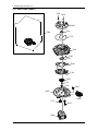
3-2. Standard Disassembly Drawings
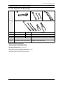
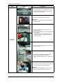
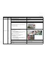
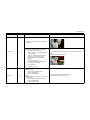
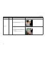
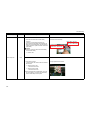
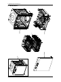
Part Photo Description
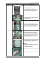
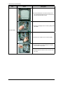
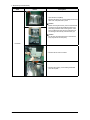
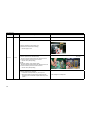
Thermistor
1. Place the dishwasher on its back so that you can
see the base. Remove the two (2) screws that hold
the base and the shutter in place.
2. Remove the leakage sensor connector (white) inside
the shutter.
3. Disconnect the wire terminal (blue) connected to the
thermistor.
4. Check the location of the thermistor and remove the
two (2) screws that hold the thermistor to the case
sump.

3-3
3. Disassembly and Reassembly
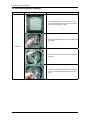
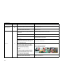
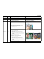
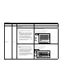
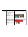
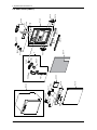
Part Photo Description
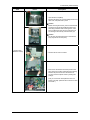
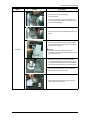
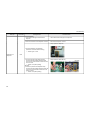
Heater
1. Open the door completely.
Remove the upper and lower baskets.
Place the baskets you’ve just removed in a safe
location so that they do not interfere with the
service operations and to prevent them from being
damaged.
2. Use your hand to hold the lower nozzle and remove
it.
Place the removed lower nozzle in a safe location
along with the bask ets.
3. Hold the nozzle duct, and rotate and remove it.
To remove it smoothly, remove the hooks clamping
the bracket duct (U) using a at screwdriver and
remove the hooks clamping the bracket duct (M).
Pull them out while rotating them to the left.
4. Remove the cover heater from the sump assy.
You will need a at screwdriver for the removal.
To remove a hook from the cover heater, insert the
end of the screwdriver into the gap between cover
heater and cover sump, and push the handle of
screwdriver and the hook.
Remove remain four(4) hooks using same way.
5. Place the dishwasher on its back so that you can
see the base. Remove the two (2) screws that hold
the base and the shutter in place.
Caution
Before placing the dishwasher on its back, make
sure to check whether any water is left. Remove
any remaining water. (There is a risk of re due to a
water leakage while servicing).
6. Remove the leakage sensor connector (white) in the
shutter.

3-4
3. Disassembly and Reassembly
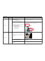
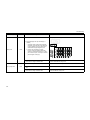
Part Photo Description
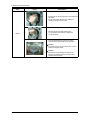
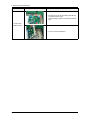
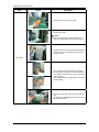
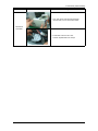
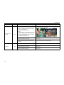
Heater
7. Remove the two (2) terminals which are inserted into
the heater.
Do not pull the wire. Remove it by holding the
metallic part at the end of the wire.
8. Remove the two (2) holder heaters which
are connected to the heater by rotating them
counterclockwise.
9. Place the dishwasher the right way up again.
Open the door and hold and remove the heater.
Caution
The heater may be very hot. Make sure to check it
before touching the heater.
Caution
Make sure to check whether any water is left.
Remove any remaining water, to prevent water
leakages while servicing.

3-5
3. Disassembly and Reassembly
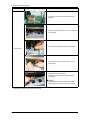
Part Photo Description
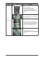
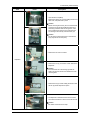
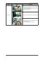
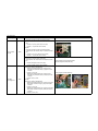
Drain Pump
1. Place the dishwasher on its back so that you can
see the base. Remove the two (2) screws that hold
the base and the shutter in place.
2. Remove the leakage sensor connector (white) in the
shutter.
3. Disconnect the two (2) drain pump connectors.
4. Remove the drain pump by rotating it
counterclockwise.
When removing the drain pump, lift up the hook
holding it in place slightly and then rotate it so that
the hook is not damaged.

3-6
3. Disassembly and Reassembly
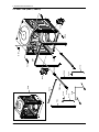
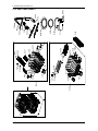
Part Photo Description
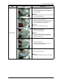
Circulation Motor
1. Open the door completely.
Remove the upper and lower baskets.
Place the baskets you’ve just removed in a safe
location so that they do not interfere with the
service operations and to prevent them from being
damaged.
2. Use your hand to hold the lower nozzle and remove
it.
Place the removed lower nozzle in a safe location
along with the baskets.
3. Hold the nozzle duct, and rotate and remove it.
To remove it smoothly, remove the hooks clamping
the bracket duc t (U) using a at screwdriver and
remove the hooks clamping the bracket duct (M).
Pull them out while rotating them to the left.
4. Remove the sump assy.
Remove the ten (10) screws on the assy lter mesh.
(Except the two (2) screws holding the holder nozzle
L in place)
Page is loading ...
Page is loading ...
Page is loading ...
Page is loading ...
Page is loading ...
Page is loading ...
Page is loading ...
Page is loading ...
Page is loading ...
Page is loading ...
Page is loading ...
Page is loading ...
Page is loading ...
Page is loading ...
Page is loading ...
Page is loading ...
Page is loading ...
Page is loading ...
Page is loading ...
Page is loading ...
Page is loading ...
Page is loading ...
Page is loading ...
Page is loading ...
Page is loading ...
Page is loading ...
Page is loading ...
Page is loading ...
Page is loading ...
Page is loading ...
Page is loading ...
Page is loading ...
Page is loading ...
Page is loading ...
Page is loading ...
Page is loading ...
Page is loading ...
Page is loading ...
Page is loading ...
Page is loading ...
Page is loading ...
Page is loading ...
Page is loading ...
Page is loading ...
Page is loading ...
Page is loading ...
Page is loading ...
Page is loading ...
Page is loading ...
Page is loading ...
Page is loading ...
Page is loading ...
Page is loading ...
Page is loading ...
Page is loading ...
Page is loading ...
Page is loading ...
Page is loading ...
Page is loading ...
Page is loading ...
Page is loading ...
Page is loading ...
Page is loading ...
Page is loading ...
Page is loading ...
Page is loading ...
Page is loading ...
Page is loading ...
Page is loading ...
Page is loading ...
Page is loading ...
Page is loading ...
Page is loading ...
Page is loading ...
Page is loading ...
Page is loading ...
Page is loading ...
Page is loading ...
Page is loading ...
Page is loading ...
Page is loading ...
Page is loading ...
Page is loading ...
Page is loading ...
Page is loading ...
Page is loading ...
-
 1
1
-
 2
2
-
 3
3
-
 4
4
-
 5
5
-
 6
6
-
 7
7
-
 8
8
-
 9
9
-
 10
10
-
 11
11
-
 12
12
-
 13
13
-
 14
14
-
 15
15
-
 16
16
-
 17
17
-
 18
18
-
 19
19
-
 20
20
-
 21
21
-
 22
22
-
 23
23
-
 24
24
-
 25
25
-
 26
26
-
 27
27
-
 28
28
-
 29
29
-
 30
30
-
 31
31
-
 32
32
-
 33
33
-
 34
34
-
 35
35
-
 36
36
-
 37
37
-
 38
38
-
 39
39
-
 40
40
-
 41
41
-
 42
42
-
 43
43
-
 44
44
-
 45
45
-
 46
46
-
 47
47
-
 48
48
-
 49
49
-
 50
50
-
 51
51
-
 52
52
-
 53
53
-
 54
54
-
 55
55
-
 56
56
-
 57
57
-
 58
58
-
 59
59
-
 60
60
-
 61
61
-
 62
62
-
 63
63
-
 64
64
-
 65
65
-
 66
66
-
 67
67
-
 68
68
-
 69
69
-
 70
70
-
 71
71
-
 72
72
-
 73
73
-
 74
74
-
 75
75
-
 76
76
-
 77
77
-
 78
78
-
 79
79
-
 80
80
-
 81
81
-
 82
82
-
 83
83
-
 84
84
-
 85
85
-
 86
86
-
 87
87
-
 88
88
-
 89
89
-
 90
90
-
 91
91
-
 92
92
-
 93
93
-
 94
94
-
 95
95
-
 96
96
-
 97
97
-
 98
98
-
 99
99
-
 100
100
-
 101
101
-
 102
102
-
 103
103
-
 104
104
-
 105
105
-
 106
106


Samsung DMR77LHB/XAC User manual
- Category
- Dishwashers
- Type
- User manual
Ask a question and I''ll find the answer in the document
Finding information in a document is now easier with AI
Related papers
-
Samsung DMT SERIES User manual
-
-
-
Samsung DMR78AHB Installation guide
-
Samsung DW80B7070US User manual
-
-
Samsung DMT700 series User manual
-
-
-
Samsung SM-F926B Operating instructions
Other documents
-
Dura Faucet DF-PK160-VB User manual
-
 Pacific Bay PB-K11SN User manual
-
Becken MAQ LAVAR LOICA 6T BDW4328 Owner's manual
-
Maytag MAV6000 User manual
-
Faber-Castell Pom Pictures - #6268000 Operating instructions
-
Hauck Pom Operating instructions
-
Fluidwell F074 Owner's manual
-
Pepperl+Fuchs OHV1000-F223-R2 Quick start guide
-
-
