Page is loading ...

ITEM #0747612
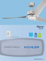
MODEL #35153
LED CEILING FAN
1
ATTACH YOUR RECEIPT HERE
Serial Number
Purchase Date
Questions, problems, missing parts? Before returning to your retailer, call our customer
service department at 1-800-554-6504, 8 a.m. - 4:30 p.m, EST, Monday - Friday.
Français p. 17
Español p. 33
Distributed by Kichler® LLC. All Rights Reserved.

PACKAGE CONTENTS
2
A
Hanging Bracket
Down Rod
Canopy
Blade Iron
Motor Coupling Cover
Motor Assembly
B
C
D
E
F
1
1
1
5
1
1
PART DESCRIPTION QTY
LED Housing
Light Kit
Canopy Hole Cover
Shade
Blade
H
G
I
J
K
1
1
1
1
5
PART DESCRIPTION QTY
A
K
K
C
I
I
E
G
B
D
F
J
H

HARDWARE CONTENTS
3
SAFETY INFORMATION
Hanging bracket Screw
Hanging bracket Washer
Wire Connector
Blade Screw
Balance Kit
HARDWARE BAG REMOTE CONTROL
Remote Control
Receiver
Battery
Wood Screw
Lag Screw
Wire Connector
Blade Iron Screws
Flat Washer + Spring Washer
Please read and understand this entire manual before attempting to assemble, operate or install the
product. If you have any questions regarding the product, please call customer service at
1-800-554-6504, 8 a.m. - 4:30 p.m., EST.
WARNING:
• Important: When using an existing outlet box, be sure the box is securely attached to the building
structure and can support the full weight of the fan. Failure to do so can result in serious injury or
death.
• Turn off circuit breakers and wall switch to the fan supply wire leads. Warning: Failure to
disconnect power supply prior to installation may result in serious injury or death.
• Warning - Connecting this fan to a light switch (on/off) has been known to cause damage to the
receiver. This fan must be wired to continually receive power. Failure to do so will drastically
reduce the lifespan of this fan.
• Do not install fan on a ceiling with a pitch greater than 20°.
• Important: Be sure wiring box is properly grounded or that a ground (green) wire is present.
• Make sure the installation site you choose allows a minimum of 7 feet from the floor to the end of
the blades.
• To reduce the risk of fire or electrical shock, do not use this fan with any solid state fan speed
device or variable speed control.
• Do not touch hot LED
• The LED light output is strong enough to injure human eyes. Precautions must be taken to
prevent looking directly at the LEDs with unaided eyes for more than a few seconds.

WARNING (continued)
CAUTION:
PREPARATION
4
Before beginning assembly of product, make sure all parts are present. Compare parts with package
contents list and diagram. If any part is missing or damaged, do not attempt to assemble the product.
Contact customer service for replacement parts.
Estimated assembly time: 30 minutes to 1 hour.
Tools Required for Assembly (not included): Phillips screwdriver, flathead screwdriver, wire strippers,
electrical tape, ladder, safety glasses.
A B C
ASSEMBLY INSTRUCTIONS
• WARNING-To reduce risk of fire, electric shock, or personal injury, mount to outlet box marked
“Acceptable for Fan Support of 15.9kg (35lbs) or less” and use mounting screws provided with the
outlet box and/or support directly from building structure. Most outlet boxes commonly used for
the support of luminaries are not acceptable for fan support and may need to be replaced.
Consult a qualified electrician if in doubt.
• Warning-Risk of fire, electric shock, or personal injury. Ceiling fans may be either directly
supported from a structural framing member of a building and (see examples in figures A & B) or
may be mounted to an outlet box marked acceptable for fan support of 31.8 kg (70 lbs) to 15.9kg
(35 lbs) (see example in figure C).
• Read and understand all instructions and illustrations completely before proceeding with assembly
and installation of this fixture.
• If you have any doubts about how to install this lighting fixture, or if the fixture fails to operate
completely, please contact a qualified licensed electrical contractor.
• All parts must be used as indicated in these instructions. Do not substitute any parts, leave parts
out, or use any parts that are worn out or broken. Failure to obey this instruction could invalidate
the UL listing, C.S.A. certification, and/or ETL listing of this fixture.
• This fixture is intended for installation in accordance with the National Electric Code (NEC) and all
local code specifications.
• Use ONLY the supplied LED driver to power fixture.
• Driver cable is not intended for use through or concealed behind walls, floors, or ceilings.
• This fixture is for indoor use only.
• Chemical Burn Hazard. Keep batteries away from children. This remote contains a lithium button
cell battery. If a new or used lithium button/coin cell battery is swallowed or enters the body, it can
cause severe internal burns and can lead to death in as little as 2 hours. Always completely
secure the battery compartment. If the battery compartment does not close securely, stop using
the product, remove the batteries, and keep it away from children. If you think batteries might
have been swallowed or placed inside any part of the body, seek immediate medical attention.
• Dispose of cells properly and keep away from children. Even used cells may cause injury.

ASSEMBLY INSTRUCTIONS
5
1. Secure the hanging bracket (A) to the ceiling outlet
box using hanging bracket screws and hanging
bracket washers.
Important: If attaching the fan to a sloped ceiling,
make sure open end of mounting bracket is installed
facing the roof. Do not install fan on a ceiling with a
pitch greater than 20°.
2. Loosen the set screws found on coupling on top of the motor assembly (F). Then remove the hair
and clevis pin that will be used on a later step.
1
A
Outlet Box
Hair Pin
Safety Cable
Clevis Pin
2
F
Coupling

6
ASSEMBLY INSTRUCTIONS
3. Insert down rod (B) through canopy (C), canopy hole cover (I), and motor coupling cover (E).
Feed wires from the motor assembly (F) through the down rod (B), then insert the down rod (B)
into the coupling found on top of the motor assembly (F).
4. Pass the clevis pin through the down rod (B) and coupling found on the motor assembly (F) then
secure with the hair pin. Tighten set screws found on the coupling on the motor assembly (F).
Hair Pin
Clevis Pin
Coupling
B
F
4
F
I
C
E
B
3

7
ASSEMBLY INSTRUCTIONS
5. Carefully lift the fan and seat the downrod (B)/hanger
ball assembly on the hanging bracket (A). Be sure
the groove in the ball is lined up with the tab on the
hanging bracket (A).
B
A
5
6. For Canadian installation and for USA fans over 35
lbs, the safety cable must be installed into the house
structure beams using a 3” lag screw. Make sure
that when the safety cable is fully extended the lead
wires are longer than the cable and no stress is
placed on the lead wires.
Safety
Cable
Lag
Screw
Safety
Cable
Flat
Washer
Spring
Washer
6
Safety
Cable

ASSEMBLY INSTRUCTIONS
8
7. Wiring the fan per wiring diagram and securely connect wires with wire connectors: Wrap electrical
tape (not included) around each wire connector and make sure no bare wire or wire strands are
visible after making connections.
• Connect WHITE wire from the fan to WHITE wire marked TO MOTOR N from the receiver.
• Connect BLUE wire from the fan to BLUE wire marked FOR LIGHT from the receiver.
• Connect BLACK wire from the fan to BLACK wire marked TO MOTOR L from the receiver.
• Connect BLACK wire from the outlet box to BLACK wire marked AC IN L from the receiver.
• Connect WHITE wire from the outlet box to WHITE wire marked AC IN N from the receiver.
• Connect GROUND (GREEN) wires from hanger bracket and downrod ball, to GROUND (GREEN
or BARE COPPER) from house.
7
OUTLET BOX
BLACK
(LIVE)
WHITE
(NEUTRAL)
BLACK
(AC
INPUT)
WHITE
(AC
INPUT)
WHITE
(NEUTRAL) WHITE
BARE COPPER
(GROUND)
GREEN (BRACKET)
GREEN (DOWN ROD)
BLUE (LIGHT)
BLACK (MOTOR) BLACK
BLUE

ASSEMBLY INSTRUCTIONS
9
8. Install the batteries (3-Volt 2032) into the
remote. Make sure the batteries are seated
correctly in each recess with the positive
symbol facing up, then replace battery cover.
Test the remote control by pushing any button.
A blue light should illuminate. If no blue light
appears make sure the batteries are seated
properly.
This fans control system is
equipped with 16 code combinations to
prevent possible interference from or to
other remote units. The frequency switches
on your receiver and remote control have been
preset at the factory. Remove the remote control
battery cover and make sure the switches
are set to the same position. This must be
done so that your fan will communicate
properly. If you are using more than one fan
in the same area and want to control them
separately, change one fan’s dip switch
settings in the remote control and receiver to a
new pattern.
NOTE: If not using for long periods of time,
remove battery to prevent damage to
remote control. Store the remote away from
excessive heat or humidly.
9. Once wiring step has been completed, slide the
wired remote receiver in between the hanging
bracket (A) and the top of the downrod ball (B) with
the flat side of the receiver facing the ceiling. Turn
lead wires upward and carefully push them into the
outlet box, with the white and green wires to one
side of the box and the black wires toward the other
side.
9
A
B
8
REMOTE CONTROL
RECEIVER
ON
ECE
ON ECE
ON ECE

ASSEMBLY INSTRUCTIONS
10
12. Pass blade iron (D) over blade (K) and secure to
arms with blade iron screws.
Repeat for remaining blade irons.
11. Attach blade (K) to the arm on the motor assembly
(F) with blade screws. Do not tighten blade screws
until each screw has been started. Then, tighten
each screw starting with the center screw.
Repeat for remaining blades
10. Loosen the two shoulder screws without fully
removing the hanging bracket (A). Assemble canopy
(C) by rotating keyhole slot in canopy over shoulder
screws in hanging bracket (A). Tighten shoulder
screws. Securely attach and tighten the canopy hole
cover (I) over the shoulder screws in the hanging
bracket (A) utilizing the keyhole slot twist-lock
feature.
10
A
C
I
Shoulder
Screw
11
F
Arm
K
K
D
12
Arm

ASSEMBLY INSTRUCTIONS
11
13. Remove the mounting screw marked with a red dot label from the motor assembly (F) and loosen
but do not remove the other 2. Feed the wires from the motor assembly (F) through the center
hole in the LED housing (G). Position keyhole slots around the screws and twist clockwise. Insert
the screw that you had previously removed. Tighten all screws.
13
F
G

ASSEMBLY INSTRUCTIONS
12
14.Connect wires from the motor assembly (F) to the LED kit (H). Remove 1 of 3 screws from the
LED housing (G) and loosen the other 2. Position keyhole slots around the screws and twist
clockwise. Insert the screw that you had previously removed. Tighten all screws.
H
G
F
14

ASSEMBLY INSTRUCTIONS
13
OPERATING INSTRUCTIONS
15.Screw shade (J) onto LED housing (G).
15
G
J
Speed Buttons:
Low Speed
Medium Speed
High Speed
Power Button:
This button turns the fan motor off and is also
used in the program procedure.
Light Buttons:
These two buttons turn the light ON and OFF
as well as controlling the brightness setting.
Directional Button:
This button changes the fan direction from
forward to reverse.
• In warmer weather, counterclockwise movement of the fan will result in downward
airflow creating a wind chill effect.
• In cooler weather, clockwise movement of the fan will result in upward airflow that can
help move stagnant hot air off the ceiling area.

14
STEPS TO BALANCING THE CEILING FAN
Balancing Weight
Plastic Clip
5G
• Tighten screws on the mounting bracket, outlet box, the downrod , fan blades to blade holders,
and blade holders to the motor housing.
• Measure the distance from the tip of each blade to the ceiling. All blades should have the same
vertical distance from the ceiling. Adjust any bent blade holder, by gently pressing up or down on
the brackets, until all blades are at an equal distance from the ceiling.
If wobbling persists, you may need a blade balancing kit to stabilize the ceiling fan. A blade
balancing kit consists of a plastic clip and two balancing weights.
Determining the blade that needs to be balanced is a trial-and-error task.
1. Place a numbered piece of masking tape on each blade so you don't lose track of which blade is
which.
2. One blade at a time, attach the slotted plastic clip over the center of the blade edge and turn the
fan on. Observe which blade has the clip on when the ceiling fan wobbles the least.
3. Place the plastic clip on the edge of the blade, halfway between the blade holder and the blade
tip. Turn fan on and determine improvement.
4. If there is no improvement, turn off the fan again. Slide the clip along the length of the blade to
locate the source of instability.
5. Once you've found the faulty blade, press a balancing weight on the centerline. The weight
should be parallel to the clip.
REMOTE CONTROL
Low
Speed
Reverse
Light
On / Off
Medium Speed
High
Speed
Power
OPERATING INSTRUCTIONS (continued)

15
CARE AND MAINTENANCE
At least twice a each year tighten all screws and lower canopy to check mounting bracket screws
and downrod assembly. Clean fan housing with only a soft brush or lint free cloth to avoid scratching
the finish. Clean blades with a lint free cloth. Shut off main power supply before beginning any
maintenance. Do not use water or a damp cloth to clean the ceiling fan.
FCC WARNING
This device complies with part 15 of the FCC Rules. Operation is subject to the following two
conditions: (1) This device may not cause harmful interference, and (2) this device must accept any
interference received, including interference that may cause undesired operation.
Changes or modifications not expressly approved by the party responsible for compliance could void
the user's authority to operate the equipment.
NOTE: This equipment has been tested and found to comply with the limits for a Class B digital
device, pursuant to part 15 of the FCC Rules. These limits are designed to provide reasonable
protection against harmful interference in a residential installation. This equipment generates, uses
and can radiate radio frequency energy and, if not installed and used in accordance with the
instructions, may cause harmful interference to radio communications. However, there is no
guarantee that interference will not occur in a particular installation. If this equipment does cause
harmful interference to radio or television reception, which can be determined by turning the
equipment off and on, the user is encouraged to try to correct the interference by one or more of the
following measures:
Reorient or relocate the receiving antenna, increase the separation between the equipment and
receiver, and connect the equipment into an outlet on a circiut different from that to which the fan is
connected.
WARRANTY
Kichler offers the following limited lifetime warranty to the Original Purchaser of a Kichler Ceiling Fan:
if the Fan’s motor or motor-related parts should fail due to what Kichler, in its sole discretion,
determines to be a defect in material or workmanship, Kichler will, at its option, either repair or
replace the defective part free of charge.
Except as provided below, for one (1) year following the purchase date, if any part other than the
motor or motor-related parts, including, but not limited to, blades, light kits, downrods, switches,
housing, or finish should fail due to what Kichler, in its sole discretion, determines to be a defect in
material or workmanship, Kichler, at its option, will repair or replace the defective part free of charge.
To replace a product that has a warranted defect, the Original Purchaser shall return any allegedly
defective parts or products to the authorized Kichler distributor that the product was purchased from
with PROOF OF PURCHASE, Original Purchaser’s name and return address and a description of the
claimed product defect.

16
WARRANTY (continued)
Rev. 04-16-19
If any of the warranted products are found by Kichler, in its sole discretion, to be defective, such
products will, at Kichler’s sole option and cost, be replaced, repaired or refunded less an amount
directly attributable to Original Purchaser’s prior use of the product. Kichler will return the repaired or
replaced product prepaid freight. This warranty does not cover labor or other costs or expenses to
remove or install any defective, repaired or replaced product.
The parties hereto expressly agree that Original Purchaser’s sole and exclusive remedy against
Kichler shall be for the repair, replacement or refund of defective products as provided herein. This
warranty extends only to product ownership by the Original Purchaser; is not transferable whether to
heirs, subsequent owners, or otherwise; and is void if the Original Purchaser ceases to own the
product.
This warranty does not apply to any products that have been subjected to misuse, mishandling,
misapplication, connected to voltage at more than 5% above standard North American voltage,
unusual use (including but not limited to use in an environment where the annual average ambient
operating temperature is below 27 or above 95 degrees Fahrenheit), neglect (including but not limited
to improper maintenance), accident, acts of god such as high winds, improper installation or care,
failure to follow the Product’s written instructions for normal use and care, improper packaging of
products returned to Kichler, modification (including but not limited to use of unauthorized parts or
attachments), or adjustment or repair. Significant product exposure to chemicals, harsh cleaners, salt
water or salt air will void any and all warranties on exterior finishes. This warranty only applies when
all components, including transformers, have been provided by Kichler. Substituting another
manufacturer’s product and/or components will render the warranty completely void.
THIS WARRANTY GIVES YOU SPECIFIC LEGAL RIGHTS. YOU MAY ALSO HAVE OTHER
RIGHTS, WHICH VARY FROM STATE TO STATE. SOME STATES DO NOT ALLOW LIMITATIONS
ON HOW LONG AN IMPLIED WARRANTY LASTS OR THE EXCLUSION OR LIMITATION OF
INCIDENTAL OR CONSEQUENTIAL DAMAGES SO THE ABOVE LIMITATIONS OR EXCLUSIONS
MAY NOT APPLY TO YOU.
THE FOREGOING WARRANTY IS IN LIEU OF ALL OTHER WARRANTIES, EXPRESS OR
IMPLIED, INCLUDING THOSE OF MERCHANTABILITY, FITNESS FOR ANY PARTICULAR
PURPOSE OR INFRINGEMENT. ORIGINAL PURCHASER SHALL IN NO EVENT BE ENTITLED
TO, AND KICHLER LIGHTING SHALL NOT BE LIABLE FOR, INDIRECT, SPECIAL, INCIDENTAL
OR CONSEQUENTIAL DAMAGES OF ANY NATURE, INCLUDING, BUT NOT LIMITED TO LOSS
OF PROFIT, PROMOTIONAL AND/OR MANUFACTURING EXPENSES, OVERHEAD, INJURY TO
REPUTATION AND/OR LOSS OF CUSTOMERS.
Printed in China
Distributed by Kichler® LLC.
All Rights Reserved.

ARTICLE #0747612
MODÈLE #35153
VENTILATEUR DE PLAFOND À DEL
17
Des questions, des problèmes, des pièces manquantes? Avant de retourner le produit à
votre détaillant, appelez notre service à la clientèle au 1-800-554-6504, entre 8 h et 16 h 30
(HNE) du lundi au vendredi.
JOIGNEZ VOTRE REÇU ICI
Numéro de série
Date d’achat
Distribué par Kichler
®
LLC. Tous droits réservés.

CONTENU DE L’EMBALLAGE
18
A
Support de suspension
Tige
Pavillon
Support des pales
Cache raccord du moteur
Ensemble moteur
B
C
D
E
F
1
1
1
5
1
1
PIÈCE
DESCRIPTION QT
É
Boîtier DEL
Kit d'éclairage
Cache-trou du pavillon
Abat-jour
Pale
H
G
I
J
K
1
1
1
1
5
PIÈCE
DESCRIPTION QT
É
A
KK
C
II
E
G
B
D
F
J
H

QUINCAILLERIE INCLUSE
19
Vis du support de suspension
Rondelle du support de suspension
Capuchon de connexion
Vis de pale
Ensemble d'équilibrage
SACHET DE QUINCAILLERIE TÉLÉCOMMANDE
TÉLÉCOMMANDE
Récepteur
Pile
Vis à bois
Tire-fond
Capuchon de connexion
Vis du support des pales
Rondelle plate + rondelle ressort
CONSIGNES DE SÉCURITÉ
Veuillez lire et assurez-vous d'avoir compris l’intégralité du présent guide avant d’assembler, d’utiliser ou d’installer ce
produit. Si vous avez des questions concernant ce produit, veuillez appeler le service client au +1-800-554-6504, entre 8h
et 16h30, HNE.
AVERTISSEMENT :
• Important : Lorsque vous utilisez une boîte de sortie existante, assurez-vous que la boîte est fermement attachée à la
structure du bâtiment et peut supporter le poids total du ventilateur. Le non-respect de cette recommandation peut
entraîner des blessures graves ou la mort.
• Coupez les disjoncteurs et l'interrupteur mural qui contrôlent les fils d'alimentation du ventilateur. Avertissement : Si
l'alimentation électrique n'est pas coupée avant l'installation, il peut en résulter de graves blessures ou la mort.
• Avertissement – Connecter ce ventilateur à un interrupteur pour lampe (marche/arrêt) endommage le récepteur. Ce
ventilateur doit être câblé afin de recevoir du courant en continu. Le non-respect de cette recommandation réduira
considérablement la durée de vie de ce ventilateur.
• Ne pas installer sur un plafond incliné à plus de 20°.
• IMPORTANT : Assurez-vous que le boîtier de connexion est correctement mis à la terre ou qu'un fil de terre (vert) est
présent.
• Assurez-vous que le site d'installation choisi offre une hauteur minimum de 2,13 m (7 pi) entre le sol et le dessous
des pales.
• Pour réduire les risques d'incendie ou de choc électrique, n'utilisez pas ce ventilateur avec une commande de vitesse
à semi-conducteurs ou une commande de variation de vitesse.
• Ne touchez pas les DEL chaudes.
• La lumière produite par les DEL est assez puissante pour blesser les yeux humains. Il est impératif de prendre des
précautions pour éviter de recevoir directement dans les yeux non protégés la lumière des DEL pendant plus de
quelques secondes.

AVERTISSEMENT (suite)
ATTENTION:
PRÉPARATION
20
Avant de commencer l’assemblage du produit, assurez-vous que toutes les pièces sont présentes. Comparez les pièces
avec la liste du contenu de l’emballage et la liste de la quincaillerie. En cas de pièces manquantes ou endommagées, ne
tentez pas d’assembler le produit.
Temps d’assemblage approximatif : de 30 à 60 minutes.
Outils nécessaires pour l’assemblage (non inclus) : tournevis cruciforme, tournevis à tête plate, pinces à dénuder, ruban
isolant, escabeau, lunettes de sécurité.
A B C
INSTRUCTIONS POUR L'ASSEMBLAGE
• AVERTISSEMENT – Pour réduire le risque d'incendie, de choc électrique ou de blessures corporelles, installez le
ventilateur sur une boîte de sortie marquée "Convient pour supporter un ventilateur de 15,9 kg (35 lb) maximum" et
utilisez les vis de montage fournies avec la boîte de sortie et/ou fixez directement sur la structure du bâtiment. La
plupart des boîtes de sortie utilisées couramment comme support de luminaires ne conviennent pas au support d'un
ventilateur et devront être remplacées. Consultez un électricien qualifié de cas de doute.
• Avertissement - Risque d'incendie, de choc électrique ou de blessures corporelles. Les ventilateurs de plafond
peuvent être fixés directement sur un élément porteur de la structure du bâtiment (voir exemples sur les figures A et
B) et/ou être montés sur une boîte de sortie marquée "Convient pour supporter un ventilateur de 15,9 kg (35 lb) à
31,8 kg (70 lb)" (voir exemple sur la figure C).
• Risque de brûlure chimique. Gardez les piles hors de portée des enfants. Cette télécommande contient une pile
bouton au lithium. Si une pile bouton au lithium neuve ou usagée est avalée ou pénètre dans le corps, elle peut
entraîner de graves brûlures internes et entraîner la mort en moins de 2 heures. Verrouillez toujours complètement le
compartiment des piles. Si le compartiment des piles ne se ferme pas correctement, cessez d'utiliser l'appareil, retirez
les piles et gardez l’appareil hors de portée des enfants. Si vous pensez que des piles ont pu être avalées ou placées
à l'intérieur d'une partie du corps, consultez immédiatement un médecin.
• Jetez les piles de façon appropriée et conservez-les hors de portée des enfants. Même des piles usagées peuvent
provoquer des blessures.
• Prenez soin de lire et de comprendre l'intégralité des instructions et des illustrations avant de commencer
l’assemblage et l’installation de cet appareil.
• Si vous avez des doutes à propos de l’installation, ou si le luminaire ne fonctionne pas correctement, veuillez
contacter un électricien qualifié agréé.
• Toutes les pièces doivent être utilisées tel qu’indiqué dans ces instructions. Ne remplacez pas les pièces, n'en
laissez pas de côté et ne les utilisez pas si elles sont usées ou brisées. Le non-respect de ces instructions peut
annuler les homologations UL, CSA et/ou ETL de cet appareil.
• Cet appareil est conçu pour une installation en conformité avec le code électrique national des États-Unis (National
Electric Code - NEC) et avec toutes les spécifications du code électrique local.
• Utilisez UNIQUEMENT le pilote de DEL fourni pour faire fonctionner le luminaire.
• Le câble du pilote n'est pas conçu pour une utilisation à travers ou dissimulée derrière les murs, les sols ou les
plafonds.
• Cet appareil est conçu pour une utilisation en intérieur uniquement.
/