
HIMatrix
Safety-Related Controller
DI 24 01 Manual
HIMA Paul Hildebrandt GmbH + Co KG
Industrial Automation
Rev. 1.00 HI 800 201 E

HI 800 201 E Rev. 1.00 (1014)
All HIMA products mentioned in this manual are protected by the HIMA trade-mark. Unless noted
otherwise, this also applies to other manufacturers and their respective products referred to herein.
All of the instructions and technical specifications in this manual have been written with great care and
effective quality assurance measures have been implemented to ensure their validity. For questions,
please contact HIMA directly. HIMA appreciates any suggestion on which information should be
included in the manual.
Equipment subject to change without notice. HIMA also reserves the right to modify the written material
without prior notice.
For further information, refer to the CD-ROM and our website http://www.hima.de and
http://www.hima.com.
© Copyright 2010, HIMA Paul Hildebrandt GmbH + Co KG
All rights reserved
Contact
HIMA Address
HIMA Paul Hildebrandt GmbH + Co KG
P.O. Box 1261
68777 Brühl, Germany
Tel: +49 6202 709-0
Fax: +49 6202 709-107
E-mail: [email protected]
Type of Change
Revision
index
Revisions
technical editorial
1.00 Added: Configuration with SILworX X X

DI 24 01 Table of Contents
HI 800 201 E Rev. 1.00 Page 3 of 34
Table of Contents
1 Introduction ............................................................ 5
1.1 Structure and Use of this Manual......................................................................... 5
1.2 Target Audience..................................................................................................... 6
1.3 Formatting Conventions ....................................................................................... 7
1.3.1 Safety Notes ............................................................................................................ 7
1.3.2 Operating Tips ......................................................................................................... 8
2 Safety...................................................................... 9
2.1 Intended Use .......................................................................................................... 9
2.1.1 Environmental Requirements................................................................................... 9
2.1.2 ESD Protective Measures........................................................................................ 9
2.2 Residual Risk ....................................................................................................... 10
2.3 Safety Precautions............................................................................................... 10
2.4 Emergency Information....................................................................................... 10
3 Product Description .............................................. 11
3.1 Safety Function.................................................................................................... 11
3.1.1 Safety-Related Analog Inputs ................................................................................ 11
3.1.1.1 Reaction in the Event of a Fault............................................................................. 11
3.2 Equipment, Scope of Delivery............................................................................ 11
3.3 Type Label............................................................................................................ 12
3.4 Assembly.............................................................................................................. 13
3.4.1 Block Diagram........................................................................................................ 13
3.4.2 Front View.............................................................................................................. 14
3.4.3 Status Indicators .................................................................................................... 15
3.4.4 I/O LEDs ................................................................................................................ 15
3.5 Product Data......................................................................................................... 15
4 Start-Up................................................................. 16
4.1 Installation and Mounting ................................................................................... 16
4.1.1 Mounting and Removing the Modules ................................................................... 16
4.1.2 Connecting the Digital Inputs................................................................................. 17
4.1.2.1 Surges on Digital Inputs......................................................................................... 18
4.1.3 Mounting the DI 24 01 in Zone 2............................................................................ 19
4.2 Configuration ....................................................................................................... 20
4.2.1 Module Slots .......................................................................................................... 20
4.3 Configuring the Module with SILworX............................................................... 20
4.3.1 Parameters and Error Codes for the Inputs ........................................................... 21
4.3.2 Digital Inputs .......................................................................................................... 21
4.3.2.1 Module Tab ........................................................................................................... 21
4.3.2.2 DI 24 01: Channels Tab......................................................................................... 21

Table of Contents DI 24 01
Page 4 of 34 HI 800 201 E Rev. 1.00
4.4 Configuring a Module Using ELOP II Factory....................................................22
4.4.1 Configuring the Inputs ............................................................................................ 22
4.4.2 Signals and Error Codes for the Inputs .................................................................. 22
4.4.2.1 Digital Inputs...........................................................................................................22
5 Operation .............................................................. 23
5.1 Handling................................................................................................................23
5.2 Diagnosis ..............................................................................................................23
6 Maintenance.......................................................... 24
6.1 Faults.....................................................................................................................24
6.2 Maintenance Measures........................................................................................25
6.2.1 Loading the Operating System............................................................................... 25
6.2.2 Proof Test...............................................................................................................25
7 Decommissioning.................................................. 26
8 Transport .............................................................. 27
9 Disposal................................................................ 28
Appendix............................................................... 29
Glossary................................................................................................................29
Index of Figures....................................................................................................30
Index of Tables .....................................................................................................31
Index......................................................................................................................32

DI 24 01 1 Introduction
HI 800 201 E Rev. 1.00 Page 5 of 34
1 Introduction
This manual describes the technical characteristics of the module and its use. It also
includes instructions on how to install, start up and replace it.
1.1 Structure and Use of this Manual
The content of this manual is part of the hardware description of the HIMatrix
programmable electronic system.
This manual is organized in the following main chapters:
Introduction
Safety
Product Description
Start-Up
Operation
Maintenance
Decommissioning
Transport
Disposal
This manual distinguishes between the following variants of the HIMatrix system:
Programming tool Processor operating system
Communication operating
system
SILworX Version 7 and beyond Version 12 and beyond
ELOP II Factory Versions prior to 7 Versions prior to 12
Table 1: HIMatrix System Variants
The manual distinguishes among the different variants using:
Separated chapters
Tables differentiating among the versions, e.g., version 7 and beyond, or prior to
version 7
i
Projects created with ELOP II Factory cannot be edited with SILworX, and vice versa!
i
This manual usually refers to compact controllers and remote I/Os as devices, and to the
plug-in cards of a modular controller as modules.

1 Introduction DI 24 01
Page 6 of 34 HI 800 201 E Rev. 1.00
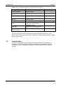
Additionally, the following documents must be taken into account:
Name Content Document number
HIMatrix System Manual
Compact Systems
Hardware description of the HIMatrix
compact systems
HI 800 141 E
HIMatrix System Manual
Modular System F60
Hardware description of the HIMatrix
modular system
HI 800 191 E
Himatrix Safety Manual
Safety functions of the HIMatrix
system
HI 800 023 E
HIMatrix Engineering
Manual
Project planning description for
HIMatrix systems
HI 800 101 E
SILworX Online Help Instructions on how to use SILworX -
ELOP II Factory Online
Help
Instructions on how to use ELOP II
Factory, Ethernet IP protocol,
INTERBUS protocol
-
First Steps
SILworX
Introduction to SILworX using the
HIMax system as an example
HI 801 103 E
First Steps
ELOP II Factory
Introduction to ELOP II Factory HI 800 006 E
Table 2: Additional Relevant Documents
The latest manuals can be downloaded from the HIMA website www.hima.com. The
revision index on the footer can be used to compare the current version of existing manuals
with the Internet edition.
1.2 Target Audience
This document addresses system planners, configuration engineers, programmers of
automation devices and personnel authorized to implement, operate and maintain the
modules and systems. Specialized knowledge of safety-related automation systems is
required.

DI 24 01 1 Introduction
HI 800 201 E Rev. 1.00 Page 7 of 34
1.3 Formatting Conventions
To ensure improved readability and comprehensibility, the following fonts are used in this
document:
Bold:
To highlight important parts
Names of buttons, menu functions and tabs that can be clicked and
used in the programming tool.
Italics:
For parameters and system variables
Courier
Literal user inputs
RUN Operating state are designated by capitals
Chapter 1.2.3
Cross references are hyperlinks even though they are not
particularly marked. When the cursor hovers over a hyperlink, it
changes its shape. Click the hyperlink to jump to the corresponding
position.
Safety notes and operating tips are particularly marked.
1.3.1 Safety Notes
The safety notes are represented as described below.
These notes must absolutely be observed to reduce the risk to a minimum. The content is
structured as follows:
Signal word: danger, warning, caution, notice
Type and source of danger
Consequences arising from the danger
Danger prevention
The signal words have the following meanings:
Danger indicates hazardous situation which, if not avoided, will result in death or serious
injury.
Warning indicates hazardous situation which, if not avoided, could result in death or
serious injury.
Warning indicates hazardous situation which, if not avoided, could result in minor or
modest injury.
Notice indicates a hazardous situation which, if not avoided, could result in property
damage.
NOTE
Type and source of damage!
Damage prevention
SIGNAL WORD
Type and source of danger!
Consequences arising from the danger
Danger prevention

1 Introduction DI 24 01
Page 8 of 34 HI 800 201 E Rev. 1.00
1.3.2 Operating Tips
Additional information is structured as presented in the following example:
i
The text corresponding to the additional information is located here.
Useful tips and tricks appear as follows:
TIP
The tip text is located here.

DI 24 01 2 Safety
HI 800 201 E Rev. 1.00 Page 9 of 34
2 Safety
The following safety information, notes and instructions must be strictly observed. The
product may only be used if all guidelines and safety instructions are adhered to.
This product is operated with SELV or PELV. No imminent danger results from the product
itself. The use in Ex-Zone is permitted if additional measures are taken.
2.1 Intended Use
HIMatrix components are designed for assembling safety-related controller systems.
When using the components in the HIMatrix system, comply with the following general
requirements
2.1.1 Environmental Requirements
Requirement type Range of values
Protection class Protection class III in accordance with IEC/EN 61131-2
Ambient temperature 0...+60 °C
Storage temperature -40...+85 °C
Pollution Pollution degree II in accordance with IEC/EN 61131-2
Altitude < 2000 m
Enclosure Standard: IP20
Supply voltage 24 VDC
Table 3: Environmental Requirements
Exposing the HIMax system to environmental conditions other than those specified in this
manual can cause the HIMatrix system to malfunction.
2.1.2 ESD Protective Measures
Only personnel with knowledge of ESD protective measures may modify or extend the
system or replace devices.
NOTE
Device damage due to electrostatic discharge!
When performing the work, make sure that the workspace is free of static and
wear an ESD wrist strap.
If not used, ensure that the device is protected from electrostatic discharge, e.g.,
by storing it in its packaging.

2 Safety DI 24 01
Page 10 of 34 HI 800 201 E Rev. 1.00
2.2 Residual Risk
No imminent danger results from a HIMatrix system itself.
Residual risk may result from:
Faults in the engineering
Faults in the user program
Faults in the wiring
2.3 Safety Precautions
Observe all local safety requirements and use the protective equipment required on site.
2.4 Emergency Information
A HIMatrix system is a part of the safety equipment of a site. If a device or a module fails,
the site adopts the safe state.
In case of emergency, no action that may prevent the HIMatrix systems from operating
safely is permitted.

DI 24 01 3 Product Description
HI 800 201 E Rev. 1.00 Page 11 of 34
3 Product Description
DI 24 01 is a plug-in module for the modular F60 HIMatrix system.
The module can be inserted in the F60 subrack's slot 3...8 as many times as required.
Slots 1 and 2 are reserved for the power supply module and CPU module, respectively.
The DI 24 01 module has 24 digital input channels for 110 VDC or 127 VAC that are
galvanically isolated from the I/O bus. The status of the signal inputs is displayed by LEDs
located on the front plate next to the terminal plugs.
The module has been certified by the TÜV for safety-related applications up to SIL 3 (IEC
61508, IEC 61511 and IEC 62061), Cat. 4 (EN 954-1) and PL e (EN ISO 13849-1). Further
safety standards, application standards and test standards are specified in the certificate
available on the HIMA website.
3.1 Safety Function
The module is equipped with safety-related analog inputs.
3.1.1 Safety-Related Analog Inputs
The module DI 24 01 has 24 digital input channels for 110 VDC or 127 VAC.
3.1.1.1 Reaction in the Event of a Fault
If the module detects a fault on a digital input, the user program processes a low level in
accordance with the de-energized to trip principle.
The module activates the FAULT LED.
In addition to the channel signal value, the user program must also consider the
corresponding error code.
The error code allows the user to configure additional fault reactions in the user program.
3.2 Equipment, Scope of Delivery
The following list specifies the available components and the corresponding part numbers:
Designation Description Part no.
DI 24 01 Plug-in module with 24 digital inputs, SIL3/Cat.4
110 VDC/127 VAC
98 2200113
Table 4: Part Numbers

3 Product Description DI 24 01
Page 12 of 34 HI 800 201 E Rev. 1.00
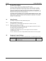
3.3 Type Label
The type plate contains the following details:
Product name
Bar code (1D or 2D code)
Part no.
Production year
Hardware revision index (HW Rev.)
Firmware revision index (FW Rev.)
Operating voltage
Mark of conformity
Figure 1: Sample Type Label

DI 24 01 3 Product Description
HI 800 201 E Rev. 1.00 Page 13 of 34
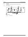
3.4 Assembly
This chapter describes the layout and function of the plug-in module.
3.4.1 Block Diagram
Test
24 Channels
I/O Bus
Figure 2: Block Diagram

3 Product Description DI 24 01
Page 14 of 34 HI 800 201 E Rev. 1.00
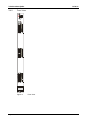
3.4.2 Front View
DI 24
01
Figure 3: Front View

DI 24 01 3 Product Description
HI 800 201 E Rev. 1.00 Page 15 of 34
3.4.3 Status Indicators
LED Color Status Description
On Operating voltage present RUN Green
Off No operating voltage
On
Module faulty or external faults
Reaction as dictated by the diagnosis
ERR Red
Off No module faults and / or no channel faults
Table 5: Status Indicators
3.4.4 I/O LEDs
LED Color Status Description
On The related channel is active (energized). I1...I16 Yellow
Off The related channel is inactive (de-energized).
Table 6: I/O LEDs
3.5 Product Data
General
Operating voltage
24 VDC, -15 %...+20 %, w
ss
≤ 15 %,
provided by a power supply unit with safe isolation
in accordance with IEC 61131-2 requirements.
Operating data
3.3 VDC / 0.05 A
24 VDC / 0.1 A (High level = 79 V)
Ambient temperature 0 °C...+60 °C
Storage temperature -40 °C...+85 °C
Space requirement 6 RU, 4 HP
Weight 260 g
Table 7: Product Data
Digital inputs
Number of inputs 24 (galvanically isolated)
Input voltage
High level
Low level
110 VDC nom. 127 VAC (monophase)
≥ 79 V
≤ 20 V
Input current
High level
≥ 2.2 mA at 79 V
Table 8: Specifications for Digital Inputs

4 Start-Up DI 24 01
Page 16 of 34 HI 800 201 E Rev. 1.00
4 Start-Up
To start up the controller, it must be mounted, connected and configured in the
programming tool.
4.1 Installation and Mounting
The module is mounted in the subrack of the modular HIMatrix F60 system.
4.1.1 Mounting and Removing the Modules
To mount and remove the modules, the connection cable clamp terminals must be
unplugged.
Additionally, personnel must be protected from electrostatic discharge. For details, refer to
Chapter
2.1.2.
Mounting the Modules
To mount a module into the rack
1. Insert the module as far as it can go – without jamming it – into the two guiding rails
which are located on the upper and lower part of the enclosure.
2. Apply pressure to the upper and lower extremity of the front plate until the module plugs
snap into the backplane socket.
3. Secure the module with the screws located on upper and lower extremity of the front
plate.
The module is mounted.
Removing the Modules
To remove a module from the rack
1. Remove the plugs from the module front plate.
2. Release the locking screws located on the upper and lower extremity of the front plate.
3 Loosen the module using the handle located on the lower part of the front plate and
remove it from the guiding rails.
The module is removed.

DI 24 01 4 Start-Up
HI 800 201 E Rev. 1.00 Page 17 of 34
4.1.2 Connecting the Digital Inputs
The use of shielded cables is not required, but improves the EMC conditions significantly.
To allow the connection of the clamps to the earth grid of the F60, the diameter of the cable
shielding should not exceed 12 mm.
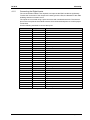
The inputs are connected using 9-pole connectors with numbered terminals. The terminal
pins on the front plate of the module have the same numbered sequence to avoid improper
connections.
Use the following terminals to connect the inputs:
Terminal Designation Function
01 I1 Input 1
02 I2 Input 2
03 I3 Input 3
04 I4 Input 4
05 I5 Input 5
06 I6 Input 6
07 I7 Input 7
08 I8 Input 8
09 N/- Common ground
Terminal Designation Function
10 I9 Input 9
11 I10 Input 10
12 I11 Input 11
13 I12 Input 12
14 I13 Input 13
15 I14 Input 14
16 I15 Input 15
17 I16 Input 16
18 N/- Common ground
Terminal Designation Function
19 I17 Input 17
20 I18 Input 18
21 I19 Input 19
22 I20 Input 20
23 I21 Input 21
24 I22 Input 22
25 I23 Input 23
26 I24 Input 24
27 N/- Common ground
Table 9: Terminal Assignment for the Inputs

4 Start-Up DI 24 01
Page 18 of 34 HI 800 201 E Rev. 1.00
4.1.2.1 Surges on Digital Inputs
Due to the short cycle time of the HIMatrix systems, a surge pulse as described in
EN 61000-4-5 can be read in to the digital inputs as a short-term high level.
The following measures ensure proper operation in environments where surges may occur:
1. Install shielded input wires
2. Activate noise blanking: a signal must be present for at least two cycles before it is
evaluated.
i
Activating noise blanking increases the response time of the HIMatrix system!
i
The measures specified above are not necessary if the plant design precludes surges from
occurring within the system.
In particular, the design must include protective measures with respect to overvoltage,
lightning, earth grounding and plant wiring in accordance with the relevant standards and
the instructions specified in the System Manual (HI 800 141 E or HI 800 191 E).

DI 24 01 4 Start-Up
HI 800 201 E Rev. 1.00 Page 19 of 34
4.1.3 Mounting the DI 24 01 in Zone 2
(EC Directive 94/9/EC, ATEX)
The device is suitable for mounting in zone 2. Refer to the corresponding declaration of
conformity available on the HIMA website.
When mounting the device, observe the special conditions specified in the following
section.
Special Conditions X
1. The F60 DI 24 01 module must be mounted in an enclosure, which fulfills the
requirements of the EN 60079-15 with the type of protection at least IP54, according to
EN 60529. Provide the enclosure with the following label:
Work is only permitted in the de-energized state
Exception:
If a potentially explosive atmosphere has been precluded, work can also performed
when the controller is under voltage.
2 The enclosure in use must be able to safely dissipate the generated heat. The power
dissipation of the module is 3.1 W at maximum depending on the power supply voltage.
3. The HIMatrix DI 24 01 module must be supplied with 24 VDC from a power supply unit
with safe isolation. Use only power supply units of type PELV or SELV.
4. Applicable standards:
VDE 0170/0171 Part 16, DIN EN 60079-15: 2004-5
VDE 0165 Part 1, DIN EN 60079-14: 1998-08
Pay particular attention to the following sections:
DIN EN 60079-15:
Chapter 5 Design
Chapter 6 Terminals and cabling
Chapter 7 Air and creeping distances
Chapter 14 Connectors
DIN EN 60079-14:
Chapter 5.2.3 Equipment for use in zone 2
Chapter 9.3 Cabling for zones 1 and 2
Chapter 12.2 Equipment for zones 1 and 2
The controller is additionally equipped with the label represented below:
Figure 4: Label for Ex Conditions

4 Start-Up DI 24 01
Page 20 of 34 HI 800 201 E Rev. 1.00
4.2 Configuration
The DI 24 01 module can be configured using a programming tool, SILworX or ELOP II
Factory. Which programming tool should be used depends on the revision status of the
operating system (firmware):
ELOP II Factory is required for operating system versions prior to 7.
SILworX is required for operating system version 7 and beyond.
i
ELOP II Factory is required to load a new operating system (version 7 or beyond) into a
controller with a CPU operating system version prior to 7. SILworX is then required once
the loading procedure is completed.
4.2.1 Module Slots
Slots 1 and 2 on the F60 module rack are reserved for the PS 01 power supply module and
CPU module, respectively. Any type of I/O modules can be plugged in to slots 3...8.
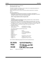
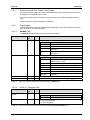
The module slots in SILworX and ELOP II Factory are numbered as follows:
Module Slot on the rack Slot in SILworX
Slot in ELOP II
Factory
PS 01 1 - -
CPU/COM 2 0/1 -
I/O 3 2 1
I/O 4 3 2
I/O 5 4 3
I/O 6 5 4
I/O 7 6 5
I/O 8 7 6
Table 10: Module Slots
i
The PS 01 power supply module is not configured.
CPU and COM are both on the F 60 CPU 01 module. In the programming tools,
however, they are represented as separated items.
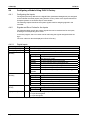
4.3 Configuring the Module with SILworX
In the Hardware Editor, the controller is represented with the following modules:
one processor module (CPU)
one communication module
6 slots available for I/O modules
To insert I/O modules, drag them from the module list onto an available slot.
Double-click the module to open the Detail View with the corresponding tabs. The tabs are
used to assign the global variables configured in the user program to the system
parameters of the corresponding module.
Page is loading ...
Page is loading ...
Page is loading ...
Page is loading ...
Page is loading ...
Page is loading ...
Page is loading ...
Page is loading ...
Page is loading ...
Page is loading ...
Page is loading ...
Page is loading ...
Page is loading ...
Page is loading ...
-
 1
1
-
 2
2
-
 3
3
-
 4
4
-
 5
5
-
 6
6
-
 7
7
-
 8
8
-
 9
9
-
 10
10
-
 11
11
-
 12
12
-
 13
13
-
 14
14
-
 15
15
-
 16
16
-
 17
17
-
 18
18
-
 19
19
-
 20
20
-
 21
21
-
 22
22
-
 23
23
-
 24
24
-
 25
25
-
 26
26
-
 27
27
-
 28
28
-
 29
29
-
 30
30
-
 31
31
-
 32
32
-
 33
33
-
 34
34


HIMA HIMatrix F60 DI 32 01 User manual
- Type
- User manual
- This manual is also suitable for
Ask a question and I''ll find the answer in the document
Finding information in a document is now easier with AI
Related papers
Other documents
-
Schneider Electric XPSMF2DO801 User manual
-
 Schweitzer Engineering Laboratories SEL-311A User manual
-
 Schweitzer Engineering Laboratories SEL-311C User manual
-
Manley Slam Owner's manual
-
-
Manley ELOP+ Owner's manual
-
SICK Flexi Compact Safety controller Operating instructions
-
WAGO Fieldbus Coupler Modbus TCP User manual
-
-

