Page is loading ...

Operator’s Manual
English (EN, GB)
Form No. 3350–931 Rev. A
Groundsmaster 4000-D
Groundsmaster Traction Unit
Model No. 30410—Serial No. 230000001 and Up

2
All Rights Reserved
Printed in the USA
2003 by The Toro Company
8111 Lyndale Avenue South
Bloomington, MN 55420-1196
CALIFORNIA
Proposition 65 Warning
Diesel engine exhaust and some of its constituents
are known to the State of California to cause
cancer, birth defects, and other reproductive harm.
Warning
Contents
Page
Introduction 3. . . . . . . . . . . . . . . . . . . . . . . . . . . . . . . . .
Safety 3. . . . . . . . . . . . . . . . . . . . . . . . . . . . . . . . . . . . . .
Safe Operating Practices 3. . . . . . . . . . . . . . . . . . . .
Toro Mower Safety 5. . . . . . . . . . . . . . . . . . . . . . . .
Sound Pressure Level 7. . . . . . . . . . . . . . . . . . . . . . .
Sound Power Level 7. . . . . . . . . . . . . . . . . . . . . . . .
Vibration Level 7. . . . . . . . . . . . . . . . . . . . . . . . . . . .
Safety and Instruction Decals 7. . . . . . . . . . . . . . . . .
Specifications 12. . . . . . . . . . . . . . . . . . . . . . . . . . . . . . . .
Traction Unit Specifications 12. . . . . . . . . . . . . . . . .
Cutting Unit Specifications 13. . . . . . . . . . . . . . . . . .
Measurements 13. . . . . . . . . . . . . . . . . . . . . . . . . . . .
Setup 14. . . . . . . . . . . . . . . . . . . . . . . . . . . . . . . . . . . . . .
Loose Parts 14. . . . . . . . . . . . . . . . . . . . . . . . . . . . . . .
Installing the Seat, Seat Belt, and Manual Tube 14. .
Greasing the Machine 14. . . . . . . . . . . . . . . . . . . . . .
Before Operating 15. . . . . . . . . . . . . . . . . . . . . . . . . . . . .
Checking the Engine Oil 15. . . . . . . . . . . . . . . . . . . .
Checking the Cooling System 16. . . . . . . . . . . . . . . .
Filling the Fuel Tank 16. . . . . . . . . . . . . . . . . . . . . . .
Checking the Hydraulic Fluid 17. . . . . . . . . . . . . . . .
Checking the Planetary Gear Drive Oil 17. . . . . . . . .
Checking the Rear Axle Lubricant 18. . . . . . . . . . . . .
Checking the Rear Axle Gear Box Lubricant 18. . . .
Checking the Tire Pressure 19. . . . . . . . . . . . . . . . . .
Checking the Torque of the Wheel Nuts or Bolts 19.
Adjusting the Height-of-Cut 19. . . . . . . . . . . . . . . . .
Adjusting the Skids 22. . . . . . . . . . . . . . . . . . . . . . . .
Adjusting the Cutting Unit Rollers 22. . . . . . . . . . . .
Correcting Mismatch Between Cutting Units 23. . . .
Operation 25. . . . . . . . . . . . . . . . . . . . . . . . . . . . . . . . . . .
Controls 25. . . . . . . . . . . . . . . . . . . . . . . . . . . . . . . . .
Starting and Stopping the Engine 27. . . . . . . . . . . . . .
Checking the Interlock Switches 27. . . . . . . . . . . . . .
Pushing or Towing the Machine 28. . . . . . . . . . . . . .
Jacking Points 29. . . . . . . . . . . . . . . . . . . . . . . . . . . . .
Tie Downs 29. . . . . . . . . . . . . . . . . . . . . . . . . . . . . . .
Operating Characteristics 29. . . . . . . . . . . . . . . . . . . .
Operating Tips 30. . . . . . . . . . . . . . . . . . . . . . . . . . . .
Maintenance 31. . . . . . . . . . . . . . . . . . . . . . . . . . . . . . . . .
Recommended Maintenance Schedule 31. . . . . . . . .
Daily Maintenance Checklist 32. . . . . . . . . . . . . . . . .
Service Interval Chart 33. . . . . . . . . . . . . . . . . . . . . .
Greasing the Bearings and Bushings 33. . . . . . . . . . .
Servicing the Air Cleaner 37. . . . . . . . . . . . . . . . . . . .
Servicing the Engine Oil and Filter 38. . . . . . . . . . . .
Servicing the Fuel System 38. . . . . . . . . . . . . . . . . . .
Bleeding Air from the Injectors 39. . . . . . . . . . . . . . .
Servicing the Engine Cooling System 40. . . . . . . . . .
Servicing the Alternator Belt 40. . . . . . . . . . . . . . . . .
Adjusting the Throttle 41. . . . . . . . . . . . . . . . . . . . . .
Servicing the Spark Arrestor Muffler 41. . . . . . . . . .
Changing the Hydraulic Fluid 41. . . . . . . . . . . . . . . .
Replacing the Hydraulic Filters 42. . . . . . . . . . . . . . .
Checking the Hydraulic Lines and Hoses 42. . . . . . .
Hydraulic System Test Ports 42. . . . . . . . . . . . . . . . .
Adjusting the Cutting Unit Flow Control 44. . . . . . .
Adjusting the Traction Pedal Linkage 44. . . . . . . . . .
Adjusting the Service Brakes 45. . . . . . . . . . . . . . . . .
Changing the Planetary Gear Drive Oil 45. . . . . . . . .
Changing the Rear Axle Lubricant 46. . . . . . . . . . . .
Checking the Rear Wheel Toe-In 47. . . . . . . . . . . . . .
Activating, Charging, and Connecting the Battery 47
Battery Care 48. . . . . . . . . . . . . . . . . . . . . . . . . . . . . .
Fuses 49. . . . . . . . . . . . . . . . . . . . . . . . . . . . . . . . . . . .
Adjusting the Transport Latch 49. . . . . . . . . . . . . . . .
Pivoting (Tilting) the Front Cutting Unit Upright 49.
Pivoting the Front Cutting Unit Down 50. . . . . . . . . .
Tensioning the Cutting Unit Drive Belts 50. . . . . . . .
Adjusting the Cutting Unit Pitch 51. . . . . . . . . . . . . .
Servicing the Castor Arm Bushings 52. . . . . . . . . . . .
Servicing the Castor Wheels and Bearings 52. . . . . .
Checking for a Bent Blade 53. . . . . . . . . . . . . . . . . . .
Removing and Installing the Cutter Blade(s) 53. . . . .
Inspecting and Sharpening the Cutter Blade(s) 53. . .
Correcting Cutting Unit Mismatch 54. . . . . . . . . . . .
Replacing the Drive Belt 54. . . . . . . . . . . . . . . . . . . .
Electrical Schematic 56. . . . . . . . . . . . . . . . . . . . . . . .
Hydraulic Schematic 57. . . . . . . . . . . . . . . . . . . . . . .
Preparing for Seasonal Storage 58. . . . . . . . . . . . . . .
The Toro General Commercial Products Warranty 60. . .

3
Introduction
Read this manual carefully to learn how to operate and
maintain your product properly. The information in this
manual can help you and others avoid injury and product
damage. Although Toro designs and produces safe
products, you are responsible for operating the product
properly and safely.
Whenever you need service, genuine Toro parts, or
additional information, contact an Authorized Service
Dealer or Toro Customer Service and have the model and
serial numbers of your product ready. The numbers can be
found on a plate that is mounted on the left side of the
operator platform, behind the footrest.
Write the product model and serial numbers in the space
below:
Model No.
Serial No.
This manual identifies potential hazards and has special
safety messages that help you and others avoid personal
injury and even death. Danger, Warning, and Caution are
signal words used to identify the level of hazard. However,
regardless of the hazard, be extremely careful.
Danger signals an extreme hazard that will cause serious
injury or death if you do not follow the recommended
precautions.
Warning signals a hazard that may cause serious injury or
death if you do not follow the recommended precautions.
Caution signals a hazard that may cause minor or moderate
injury if you do not follow the recommended precautions.
This manual uses two other words to highlight information.
Important calls attention to special mechanical
information and Note: emphasizes general information
worthy of special attention.
Safety
This machine meets or exceeds CEN standard EN
836:1997, ISO standard 5395:1990, and ANSI
B71.4-1999 specifications in effect at the time of
production.
Improper use or maintenance by the operator or owner
can result in injury. To reduce the potential for injury,
comply with these safety instructions and always pay
attention to the safety alert symbol, which means
CAUTION, WARNING, or DANGER—“personal
safety instruction.” Failure to comply with the
instruction may result in personal injury or death.
Safe Operating Practices
The following instructions are from the CEN standard EN
836:1997, ISO standard 5395:1990, and ANSI standard
B71.4-1999.
Training
•Read the Operator’s Manual and other training material
carefully. Be familiar with the controls, safety signs,
and the proper use of the equipment.
•Never allow children or people unfamiliar with these
instructions to use the mower. Local regulations may
restrict the age of the operator.
•Never mow while people, especially children, or pets
are nearby.
•Keep in mind that the operator or user is responsible for
accidents or hazards occurring to himself or herself,
other people, or property.
•Do not carry passengers.
•All drivers and mechanics should seek and obtain
professional and practical instruction. The owner is
responsible for training the users. Such instruction
should emphasize:
– the need for care and concentration when working
with ride-on machines;
– control of a ride-on machine sliding on a slope will
not be regained by the application of the brake. The
main reasons for loss of control are:
•insufficient wheel grip;
•being driven too fast;
•inadequate braking;
•the type of machine is unsuitable for its task;
•lack of awareness of the effect of ground
conditions, especially slopes;
•incorrect hitching and load distribution.
Preparation
•While mowing, always wear substantial footwear, long
trousers, hard hat, safety glasses, and ear protection.
Long hair, loose clothing or jewelry may get tangled in
moving parts. Do not operate the equipment when
barefoot or wearing open sandals.

4
•Thoroughly inspect the area where the equipment is to
be used and remove all objects which may be thrown by
the machine.
•Warning—fuel is highly flammable. Take the
following precautions:
– Store fuel in containers specifically designed for this
purpose.
– Refuel outdoors only and do not smoke while
refuelling.
– Add fuel before starting the engine. Never remove
the cap of the fuel tank or add fuel while the engine
is running or when the engine is hot.
– If fuel is spilled, do not attempt to start the engine
but move the machine away from the area of
spillage and avoid creating any source of ignition
until fuel vapors have dissipated.
– Replace all fuel tank and container caps securely.
•Replace faulty silencers/mufflers.
•Before using, always visually inspect to see that the
blades, blade bolts, and cutting assembly are not worn
or damaged. Replace worn or damaged blades and bolts
in sets to preserve balance.
•On multi-bladed machines, take care as rotating one
blade can cause other blades to rotate.
•Evaluate the terrain to determine what accessories and
attachments are needed to properly and safely perform
the job. Only use accessories and attachments approved
by the manufacturer.
•Check that operator’s presence controls, safety
switches, and shields are attached and functioning
properly. Do not operate unless they are functioning
properly.
Operation
•Do not operate the engine in a confined space where
dangerous carbon monoxide fumes can collect.
•Mow only in daylight or in good artificial light.
•Before attempting to start the engine, disengage all
blade attachment clutches, shift into neutral, and engage
the parking brake. Only start the engine from the
operator’s position. Use seat belts, if provided.
•Remember there is no such thing as a safe slope. Travel
on grass slopes requires particular care. To guard
against overturning:
– Do not stop or start suddenly when going up or
downhill.
– Engage the clutch slowly, always keep the machine
in gear, especially when travelling downhill.
– The machine speed should be kept low on slopes
and during tight turns.
– Stay alert for humps and hollows and other hidden
hazards.
– Never mow across the face of the slope, unless the
machine is designed for that purpose.
•Stay alert for holes in the terrain and other hidden
hazards.
•Use care when pulling loads or using heavy equipment.
– Use only approved drawbar hitch points.
– Limit loads to those you can safely control.
– Do not turn sharply. Use care when reversing.
– Use counterweight(s) or wheel weights when
suggested in the operator’s manual.
•Watch out for traffic when crossing or near roadways.
•Stop the blades from rotating before crossing surfaces
other than grass.
•When using any attachments, never direct discharge of
material toward bystanders nor allow anyone near the
machine while in operation.
•Never operate the machine with damaged guards,
shields, or without safety protective devices in place. Be
sure all interlocks are attached, adjusted properly, and
functioning properly.
•Do not change the engine governor settings or
overspeed the engine. Operating the engine at excessive
speed may increase the hazard of personal injury.
•Before leaving the operator’s position:
– Stop on level ground.
– Disengage the power take-off and lower the
attachments.
– Change into neutral and set the parking brake.
– Stop the engine and remove the key.
•Disengage drive to attachments, stop the engine, and
disconnect the spark plug wire(s) or remove the ignition
key:
– before clearing blockages;
– before checking, cleaning, or working on the
machine;
– after striking a foreign object. Inspect the machine
for damage and make repairs before restarting and
operating the equipment;
– if the machine starts to vibrate abnormally (check
immediately).

5
•Disengage drive to attachments when transporting or
not is use.
•Stop the engine and disengage drive to attachment:
– before refuelling;
– before making height adjustment unless adjustment
can be made from the operator’s position.
•Reduce the throttle setting before stopping engine and,
if the engine is provided with a fuel shut-off valve, turn
the fuel off at the conclusion of mowing.
•Never raise deck with the blades running.
•Keep hands and feet away from the cutting units.
•Look behind and down before backing up to be sure of
a clear path.
•Slow down and use caution when making turns and
crossing roads and sidewalks.
•Do not operate the mower under the influence of
alcohol or drugs.
•Use care when loading or unloading the machine into a
trailer or truck.
•The operator shall turn on flashing warning lights, if
provided, whenever traveling on a public road, except
where such use is prohibited by law.
Maintenance and Storage
•Keep all nuts, bolts, and screws tight to be sure the
equipment is in safe working condition.
•Never store the equipment with fuel in the tank inside a
building where fumes may reach an open flame or
spark.
•Allow the engine to cool before storing in any enclosure
and do not store near flame.
•To reduce the fire hazard, keep the engine,
silencer/muffler, battery compartment, cutting units,
drives, and fuel storage area free of grass, leaves, or
excessive grease. Clean up oil or fuel spillage.
•Replace worn or damaged parts for safety.
•If the fuel tank has to be drained, do this outdoors.
•On multi-bladed machines, take care as rotating one
blade can cause other blades to rotate.
•When machine is to be parked, stored, or left
unattended, lower the cutting units unless a positive
mechanical lock is provided.
•Disengage drives, lower the cutting units, move traction
pedal to Neutral, set parking brake, stop engine and
remove key and disconnect spark plug wire. Wait for all
movement to stop before adjusting, cleaning or
repairing.
•Shut off fuel while storing or transporting. Do not store
fuel near flames.
•Park machine on level ground. Never allow untrained
personnel to service machine.
•Use jack stands to support components when required.
•Carefully release pressure from components with stored
energy.
•Disconnect battery or remove spark plug wire before
making any repairs. Disconnect the negative terminal
first and the positive last. Reconnect positive first and
negative last.
•Use care when checking blades. Wrap the blades or
wear gloves, and use caution when servicing them.
Only replace blades. Never straighten or weld them.
•Keep hands and feet away from moving parts. If
possible, do not make adjustments with the engine
running.
•Charge batteries in an open well ventilated area, away
from spark and flames. Unplug charger before
connecting or disconnecting from battery. Wear
protective clothing and use insulated tools.
Toro Mower Safety
The following list contains safety information specific to
Toro products or other safety information that you must
know that is not included in the CEN, ISO, or ANSI
standards.
This product is capable of amputating hands and feet and
throwing objects. Always follow all safety instructions to
avoid serious injury or death.
Use of this product for purposes other than its intended use
could prove dangerous to user and bystanders.
Engine exhaust contains carbon monoxide, which
is an odorless, deadly poison that can kill you.
Do not run engine indoors or in an enclosed area.
Warning
Operation
•Before operating a machine with ROPS (roll over
protection system), be certain that the seat belts are
attached and the seat is latched to prevent the seat from
pivoting forward.
•Know how to stop the machine and engine quickly.
•Do not operate the machine while wearing tennis shoes
or sneakers.

6
•Wearing safety shoes and long pants is advisable and
required by some local ordinances and insurance
regulations.
•Keep hands, feet, and clothing away from moving parts
and the mower discharge area and underside of the
mower while the engine is running.
•Fill fuel tank until level is 1 in. (25 mm) below the
bottom of the filler neck. Do not overfill.
•Check the safety interlock switches daily for proper
operation. If a switch should fail, replace the switch
before operating the machine. After every two years,
replace all interlock switches in the safety system,
regardless if they are working properly or not.
•Check carefully for overhead clearances (i.e. branches,
doorways, electrical wires) before driving under any
objects and do not contact them.
•Do not mow in reverse unless absolutely necessary.
•Reduce speed when making sharp turns.
•If a steep slope must be ascended, back up the hill and
drive forward down the hill, keeping the machine in
gear.
•If you cannot back up a slope or if you feel uneasy on it,
do not mow it.
•Avoid starting or stopping on a slope. If tires lose
traction, disengage the blades and proceed slowly
straight down the slope. Avoid raising the side cutting
units on a slope.
•Avoid turning on slopes. If you must turn, turn slowly
and gradually downhill, if possible.
•When operating the machine on slopes, banks, or near
drop offs, always have the ROPS installed.
•When operating a machine with a ROPS, always use a
seat belt.
•Be certain that the seat belt can be released quickly if
the machine is driven or rolls into a pond or water.
•Watch for traffic when near or crossing roads. Always
yield the right-of-way.
•Do not mow near drop-offs, ditches, or embankments.
The machine could suddenly turn over if a wheel goes
over the edge of a cliff or ditch, or if an edge caves in.
•Do not mow on wet grass. Reduced traction could cause
sliding.
•Do not try to stabilize the machine by putting your foot
on the ground.
•Use extra care with other attachments. These can
change the stability of the machine.
•Turn off the blades when not mowing.
Maintenance and Storage
•Do not touch equipment or attachment parts which may
be hot from operation. Allow to cool before attempting
to maintain, adjust, or service.
•Never store the machine or fuel container inside where
there is an open flame, such as near a water heater or
furnace.
•Keep nuts and bolts tight, especially the blade
attachment bolts. Keep equipment in good condition.
•Make sure all hydraulic line connectors are tight and all
hydraulic hoses and lines are in good condition before
applying pressure to the system.
•Keep your body and hands away from pin hole leaks or
nozzles that eject hydraulic fluid under high pressure.
Use paper or cardboard, not your hands, to search for
leaks. Hydraulic fluid escaping under pressure can have
sufficient force to penetrate the skin and cause serious
injury. If fluid is injected into the skin it must be
surgically removed within a few hours by a doctor
familiar with this form of injury or gangrene may result.
•If the engine must be running to perform a maintenance
adjustment, keep hands, feet, clothing, and any parts of
the body away from the cutting units, attachments, and
any moving parts. Keep everyone away.
•Check brake operation frequently. Adjust and service as
required.
•Battery acid is poisonous and can cause burns. Avoid
contact with skin, eyes, and clothing. Protect your face,
eyes, and clothing when working with a battery.
•Battery gases can explode. Keep cigarettes, sparks, and
flames away from the battery.
•The engine must be shut off before checking the oil or
adding oil to the crankcase.
•If major repairs are ever needed or if assistance is
desired, contact an Authorized Toro Distributor.
•To make sure of optimum performance and continued
safety certification of the machine, use only genuine
Toro replacement parts and accessories. Replacement
parts and accessories made by other manufacturers
could be dangerous, and such use could void the
product warranty.

7
Sound Pressure Level
This unit has an equivalent continuous A–weighted sound
pressure level at the operator ear of 89 dBA, based on
measurements of identical machines per Directive
98/37/EC and amendments.
Sound Power Level
This unit has a guaranteed sound power level of
105 dBA/1 pW, based on measurements of identical
machines per Directive 2000/14/EC and amendments.
Vibration Level
Hand-Arm
This unit does not exceed a vibration level of 2.5 m/s2 at
the hands based on measurements of identical machines per
ISO 5349 procedures.
Whole Body
This unit does not exceed a vibration level of 0.5 m/s2 at
the posterior based on measurements of identical machines
per ISO 2631 procedures.
Safety and Instruction Decals
Safety decals and instructions are easily visible to the operator and are located near any area
of potential danger. Replace any decal that is damaged or lost.
106-6764
1. To start the engine, move the traction pedal to Neutral, press
the brake pedal, move the throttle lever to Fast, turn the ignition
key to On, and then turn the ignition key to Start; read the
Operators Manual.
2. To stop the engine, move the throttle lever to slow, disengage
the PTO, set the parking brake, wait 5 minutes, turn the ignition
key to Stop, and remove the key; read the
Operators Manual.
3. Read the
Operators Manual.
4. To engage the PTO, pull up on the PTO switch and move it
forward.
5. To disengage the PTO, move the PTO switch back.
6. To switch the transmission to high speed, raise the attachment
lift and switch the speed control to High.
93-7275
1. Read the operator’s
manual. 2. Do not use starting aids.
93-7272
1. Cutting/dismemberment hazard—stay away from moving parts.
104-4163
1. Explosion hazard
2. No fire, open flames, or
smoking.
3. Caustic liquid/chemical
burn hazard
4. Wear eye protection
5. Read the
Operator’s
Manual.
6. Keep bystanders a safe
distance from the battery.

8
104–8336
106-6756
100-6578
1. Stay away from moving parts.
2. Do not operate with cutting unit covers removed.
106-6752(replaces 106–6756 for CE)
1. Warning—read the
Operator’s Manual.
2. Warning—lock the parking brake, stop the engine, and remove
the ignition key before leaving the machine.
3. Warning—wear the seat belt when seated in the operator’s
position.
4. Cutting hazard of hand or foot—stay away from moving parts.
5. Tipping hazard—lower the cutting unit when driving down
slopes; do not drive on slopes greater than 15 degrees.
6. Thrown object hazard—keep bystanders a safe distance from
the machine.

9
106-6753 (replaces 43-8480 for CE)
1. Thrown object
hazard—keep bystanders
a safe distance from the
machine.
2. Cutting/dismemberment
hazard of hand or foot,
mower blade—stay away
from moving parts.
43-8480
104-8323
93-7818
1. Danger—read the operator’s manual for blade torque
specification.
106-6755
1. Engine coolant under
pressure
2. Explosion hazard—read
the
Operator’s Manual.
3. Warning—do not touch
the hot surface.
4. Warning—read the
Operator’s Manual.
106-6754
1. Do not touch the hot surface, and keep bystanders a safe
distance from the machine.
2. Cutting/dismemberment hazard, fan and entanglement hazard,
belt—stay away from moving parts
104-8324
1. Raise cutting units 1. Lower cutting units

10
106-2046
1. Engage
2. Power Take-off (PTO)
3. Disengage
4. High
5. Transmission
6. Low
7. Lock
8. Flow divider
9. Unlock
10. Cruise control (optional)
11. Silencer switch
12. Press the button
13. Key switch
14. Engine—preheat
15. Fast
16. Continuous variable setting
17. Slow
18. Engine coolant temperature
reset switch
104-2277
1. To lock the parking brake, latch the pedals together, apply the
brake pedals, and pull up on the knob.
2. To unlock the parking brake, step on the brake pedals.
3. Parking brake lock
4. Read the operator’s manual.
5. Press for optional headlights.
6. Press down on the lever to tilt the steering wheel.
100-5622
1. Height of cut adjustment
100-5624
1. Height of cut adjustment

11
104-3578
1. Height of cut adjustment
100-5623
1. Low height of cut adjustment
2. High height of cut adjustment
100-5693
1. Height of cut adjustment
104-8325
1. Lock/unlock the cutting unit service lock.
100-5694
1. Height of cut adjustment
104-3579
1. Low height of cut
adjustment 2. High height of cut
adjustment
104-3599
1. Do not step here.
2. Traction pedal
3. Traction—forward
4. Traction—reverse
5. Danger—shut off PTO prior to raising the cutting units.
6. Danger—do not operate the cutting units when they are in the
raised position.

12
Specifications
Traction Unit Specifications
Engine Kubota, four-cycle, four cylinder, 134 in.3 displacement, water-cooled turbo diesel
engine. Rated 58 hp @ 2600 RPM, 23:1 compression ratio. Low idle—1500 RPM,
high idle—2800 RPM. Oil capacity is 8 qt. (7.6 l) with filter.
Cooling system Capacity is 2-3/4 gallons (10.4 l) of 50/50 mixture of ethylene glycol anti-freeze.
Fuel system Electric fuel pump. Replaceable inline filter and spin-on fuel filter/water separator.
Capacity is 19 gallons (72 l) of #2 diesel fuel.
Hydraulic system Reservoir capacity is 8 gallons (30 l). Two replaceable spin-on filter elements.
Traction system
Servo-controlled hydrostatic system driving planetary gear reduction front wheel
drives. Foot pedal control of forward/reverse ground speed.
Rear drive axle coupled to hydrostatic transmission for full time 4-wheel drive when
in Mow position. A Roll Over Protective Structure (ROPS) and seat belt are
standard.
Ground speed Mow: 0-8 MPH (0-12.8 km/h)
Transport: 0-15 MPH (0-24 km/h)
Tires Front: 26x12.00–12, 6-ply, tubeless turf tire
Rear: 20x10.00–10, 6-ply, tubeless turf tire
Front and back tire pressure is 25–30 psi (172–207 kPa).
Diagnostic system Test ports for traction system, cutting unit drive system, lift/counterbalance,
lift/relief, steering circuits, and charge pressure are located near individual
components.
Steering system Automotive type, full power
Brakes Internal multiple wet disc brakes
Electrical system 12 volt, 110 minute reserve capacity (DIN) battery and 40 amp. alternator. Negative
ground. Battery type group 24.
Interlock system
Prevents engine from starting unless traction pedal is in neutral and PTO is
disengaged. If the operator leaves seat with the traction pedal depressed and the
PTO engaged, after one second the PTO will disengage and if the operator is not
back in the seat within 2 seconds the engine will stop. Engine will stop if machine
comes out of neutral with parking brake set.
Gauges, indicator lights,
and audible warning
systems
Fuel gauge, engine coolant temperature gauge, hour meter, indicator lights for high
engine coolant temperature, low engine oil pressure, glow plugs and charging.
Audible warning for low engine oil pressure and high engine temperature.
Controls Steering wheel, tilt adjustment, ignition switch, PTO switch, throttle control, traction
pedal, mow/transport speed selector switch, flow divider switch, brakes (for turning
or traction assist), parking brake pedal lock, and cutting unit lift/lower levers

13
Cutting Unit Specifications
Front cutting unit 62 in. (157 cm) width of cut, 3 blades. Cutting unit can be tipped and latched for
maintenance.
Side cutting units 42 in. (107 cm) width of cut, 2 blades
Height of cut
1-5 in. (25-177 mm) adjustable in 1/2 in. (13 mm) increments. Front cutting unit ad
justment is achieved by changing spacers on castor wheels and length of support
chains. Side cutting unit adjustment is achieved by adding or removing an equal num
ber of spacers from the castor forks, positioning the castor wheel axles in the high or
low heightofcut holes in the castor forks and securing the pivot arms to the selected
heightofcut bracket holes.
Construction Housing is made of 12 gauge steel and reinforced with channels and plates.
Cutter drive One hydraulic motor per cutting unit. Each motor powers one spindle directly while
remaining spindles are driven by a B section v-belt. Spindle shafts are supported by
two externally sealed, greaseable, tapered roller bearings. All blades, spindles and
belts are interchangeable.
Blades Seven 21-3/4 in. long, 1/4 in.
thick, heat-treated steel
Suspension and castor
wheels
Front cutting unit has two front castors, consisting of 8 in. pneumatic wheel and tire
assembly with sealed ball bearings. Rear of cutting unit is suspended from lift arms
with adjustment for cutting unit rake. Hydraulic counter balance and lift system
designed integral with cutting unit for maximum flotation and traction. Side cutting
units have two front fixed castors and one rear castor consisting of 8 in. pneumatic
wheel and tire assembly with sealed ball bearings. Inside rear of cutting unit is
suspended by a spring and damper system. Hydraulic counter balance and lift
system designed integral with cutting unit for maximum flotation and traction.
Anti-scalp features Anti-scalp cup located on each blade. Anti-scalp rollers. Adjustable skid on each
end of cutting unit.
Cutting unit covers Steel and plastic covers
Note: Specifications subject to change without notice.
Measurements
Width of cut
overall
front cutting unit
side cutting unit
front and one side cutting
unit
132 in. (335 cm)
62 in. (157 cm)
42 in. (107 cm)
97 in. (246 cm)
Overall width
cutting units down
cutting units up (transports) 136 in. (345 cm)
72 in. (183 cm)
Overall length 135 in. (342 cm)
Height 55 in. (140 cm)
Height with ROPS 81 in. (206 cm)
Ground clearance 6-1/2 in. (17 cm)
Wheel tread (to center of tire)
front
rear 45 in. (114 cm)
47 in. (119 cm)
Wheel base 55-1/2 in. (141 cm)
Weight (with cutting units and
fluids) 3860 lb. (1751 kg)

14
Setup
Note: Determine the left and right sides of the machine from the normal operating position.
Loose Parts
Note: Use this chart as a checklist to ensure that all parts necessary for assembly have been received. Without these parts,
total setup cannot be completed. Some parts may have already been assembled at the factory.
Description Qty. Use
Seat belt
Capscrew
Washer
1
2
2Installing the seat belt
Manual tube
R-clamp 1
2Installing the manual tube
EEC decals 5Apply to machine for CE compliance.
EEC certificate
Parts catalog
Pre-delivery inspection sheet
2
1
1
Operator’s manual
Engine manual
Operator Video
Registration card
2
1
1
1
Read before operating the machine.
View before operating machine
Fill out and return to Toro
Installing the Seat, Seat Belt,
and Manual Tube
The machine is shipped without the seat assembly. Deluxe
Seat Kit, Model No. 30398, and Seat Suspension Kit,
Model No. 30396, must be purchased and installed.
1. Mount the manual tube to the seat suspension with the 2
R-clamps included in loose parts.
2. Install the seat belt to each side of the seat with a bolt
and lock washer, supplied in loose parts.
Important Make sure that the seat switch wire is
connected to the seat switch connector on the harness.
3. Slide the seat completely forward and backward to
ensure proper operation and that seat switch wires and
connectors are not pinched or do no contact any moving
parts.
Greasing the Machine
Before the machine is operated, it must be greased to
ensure proper lubricating characteristics; refer to Greasing
the Bearings and Bushings. Failure to properly grease the
machine will result in premature failure of critical parts.

15
Before Operating
If you leave the key in the ignition switch, someone
could accidently start the engine and seriously
injure you or other bystanders.
Remove the key from the ignition before you do
any maintenance.
Caution
Checking the Engine Oil
Check the oil level at the beginning of each day.
The crankcase capacity is 8 qt. (7.6 l) with the filter.
1. Park the machine on a level surface. Unlock the engine
cover latches.
2. Open the engine cover.
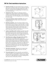
3. Remove the dipstick, wipe it clean, install the dipstick
into the tube, and pull it out again. The oil level should
be up to the FULL mark (Fig. 1).
1
Figure 1
1. Dipstick
4. If the oil is below the FULL mark, remove the fill cap
(Fig. 2) and add oil until the level reaches the FULL
mark. Do not overfill.
1
Figure 2
1. Oil fill cap
5. The engine uses any high-quality detergent oil having
the American Petroleum Institute (API) “service
classification” CD, CE, CF, CF-4, or CG-4. Use the
following chart to select the proper viscosity grade for
the temperature expected.
above 77°F (25°C) SAE 30 10W-30
or
10W-40
32° to 77°F (0° to 25°C)
SAE 20 10W-30
or
10W-40
below 32°F (0°C) SAE 10 10W-30
or
10W-40
Note: When using different oil, drain all old oil from the
crankcase before adding new oil.
6. Install the oil fill cap and dipstick.
7. Close the engine cover and secure it with the latches.

16
Checking the Cooling System
Check level of coolant at the beginning of each day.
Capacity of system is 2-3/4 gal. (10.4 l).
1. Carefully remove the radiator cap and expansion tank
cap (Fig. 3).
If the engine has been running, the pressurized,
hot coolant can escape and cause burns.
•Do not open the radiator cap when the engine is
running.
•Use a rag when opening the radiator cap, and
open the cap slowly to allow steam to escape.
Caution
2. Check the coolant level in the radiator. The radiator
should be filled to the top of the filler neck and the
expansion tank filled to the FULL mark.
1
Figure 3
1. Expansion tank
3. If the coolant is low, add a 50/50 mixture of water and
ethylene glycol anti-freeze. Do not use water only or
alcohol/methanol base coolants.
4. Install the radiator cap and expansion tank cap.
Filling the Fuel Tank
The capacity of the fuel tank is 19 gallons (72 l).
1. Remove the fuel tank cap (Fig. 4).
2. Fill the tank to about 1 inch (25 mm) below the top of
the tank, not the filler neck, with No. 2 diesel fuel. Then
install the cap.
1
Figure 4
1. Fuel tank cap
Danger
Under certain conditions, diesel fuel and fuel
vapors are highly flammable and explosive. A fire
or explosion from fuel can burn you and others
and can cause property damage.
•Use a funnel and fill the fuel tank outdoors, in
an open area, when the engine is off and is cold.
Wipe up any fuel that spills.
•Do not fill the fuel tank completely full. Add fuel
to the fuel tank until the level is 1/4 to 1/2 in. (6
to 13 mm) below the bottom of the filler neck.
This empty space in the tank allows the fuel to
expand.
•Never smoke when handling fuel, and stay away
from an open flame or where fuel fumes may be
ignited by a spark.
•Store fuel in a clean, safety-approved container
and keep the cap in place.

17
Checking the Hydraulic Fluid
The machines reservoir is filled at the factory with
approximately 8 gallons of high quality hydraulic fluid.
Check the level of hydraulic fluid before the engine is
first started and daily thereafter. Appropriate hydraulic
oils are listed below.
The following list is not assumed to be all–inclusive.
Hydraulic fluids produced by other manufacturers may be
used if they can cross reference to find an equivalent to the
products listed. Toro will not assume responsibility for
damage caused by improper substitutions, so use only
products from reputable manufacturers who will stand
behind their recommendation.
Multigrade Hydraulic Fluid – ISO VG 46
Normal Climate: 0 (–18C) to 110F (43C)
Mobil DTE 15M
Amoco Rykon Premium ISO 46
Chevron Rykon Premium Oil ISO 46
Conoco Hydroclear AW MV46
Exxon Univis N46
Pennzoil AWX MV46
Shell Tellus T 46
Texaco Rando HDZ 46
Important The ISO VG 46 Multigrade fluid has been
found to offer optimal performance in a wide range of
temperature conditions. For operation in consistently high
ambient temperatures, 65F (18C) to 120F (49C), ISO
VG 68 hydraulic fluid may offer improved performance.
Note: Many hydraulic fluids are almost colorless, making it
difficult to spot leaks. A red dye additive for the hydraulic
system oil is available in 2/3 oz. (20 ml) bottles. One bottle
is sufficient for 4–6 gal (15–22 1) of hydraulic oil. Order
part no.44–2500 from your authorized Toro distributor. Not
recommended for biodegradable fluid (use food coloring).
Biodegradable Hydraulic Fluid – Mobil 224H
Important Mobil EAL 224H is the only biodegradable
oil tested and approved by Toro. Contamination by
mineral–based hydraulic fluids will change the
biodegradability and toxicity of this oil. When changing
from standard fluid to the biodegradable type, be certain to
follow the approved flushing procedure published by
Mobil. Contact your local Toro Distributor for details. This
oil is available in 5 gallon (19 1) containers from your Toro
Distributor, order part no. 100–7674.
1. Position the machine on a level surface, lower the
cutting units, stop the engine, and remove the key.
2. Unlatch the seat, raise it, and engage the prop rod.
3. Clean the area around the filler neck and cap of the
hydraulic tank (Fig. 5). Remove the cap from the filler
neck.
4. Remove the dipstick from the filler neck and wipe it
with a clean rag. Insert the dipstick into the filler neck;
then remove it and check the fluid level. The fluid level
should be between the two marks on the dipstick.
5. If the level is low, add the appropriate fluid to raise the
level to the upper mark.
6. Install the dipstick and cap onto the filler neck.
1
Figure 5
1. Hydraulic tank cap
Checking the Planetary Gear
Drive Oil
Check the oil level after every 400 hours of operation or if
external leakage is noted. Use high quality SAE
85W-140 wt. gear lube as a replacement.
The capacity of the system is approximately 16 oz. (0.5 l).
1. With the machine on a level surface, position the wheel
so that the check/drain plug (Fig. 6) is at either the 2 or
10 o’clock position.

18
1
Figure 6
1. Check/drain plug
2. Remove the plug on the planetary (Fig. 6) and check the
plug on the back side of the brake (Fig. 7). Oil should
be at the bottom of the check plug hole on the back side
of the brake.
1
2
Figure 7
1. Brake housing 2. Check plug
3. Add gear oil to the hole in the planetary, if necessary, to
bring the oil up to the proper level. Install the plug.
4. Repeat steps 1–3 on the opposite gear assembly.
Checking the Rear Axle
Lubricant
The rear axle is shipped from the factory filled with SAE
85W-140 wt. gear lube. Check the oil level before the
engine is first started and every 400 hours thereafter. The
capacity is 80 oz. (2.4 l). Visually inspect for leaks daily.
1. Position the machine on a level surface.
2. Remove a check plug from one end of the axle (Fig. 8)
and make sure that the lubricant is up to the bottom of
the hole. If the level is low, remove the fill plug (Fig. 8)
and add enough lubricant to bring the level up to the
bottom of the check plug holes.
1
2
Figure 8
1. Check plug 2. Fill plug
Checking the Rear Axle Gear
Box Lubricant
The gear box is shipped from the factory filled with SAE
85W-140 wt. gear lube. Check the oil level before the
engine is first started and every 400 hours thereafter. The
capacity is 16 oz. (0.5 l). Visually inspect for leaks daily.
1. Position the machine on a level surface.

19
2. Remove the check/fill plug from the left side of the gear
box (Fig. 9) and make sure that lubricant is up to the
bottom of the hole. If the level is low, add enough
lubricant to bring the level up to the bottom of the hole.
1
2
Figure 9
1. Gear box 2. Check/fill plug
Checking the Tire Pressure
The tires are over-inflated for shipping. Therefore, release
some of the air to reduce the pressure. The correct air
pressure in the front and rear tires is 25–30 psi
(172–207 kPa).
Important Maintain even pressure in all tires to ensure
a good quality-of-cut and proper machine performance. Do
not under-inflate.
Checking the Torque of the
Wheel Nuts or Bolts
Failure to maintain proper torque of the wheel
nuts could result in failure or loss of wheel and
may result in personal injury.
Torque the front wheel nuts and rear bolts to
85–100 ft.-lb. (115–136 Nm) after 1–4 hours of
operation and again after 10 hours of operation.
Torque every 200 hours thereafter.
Warning
Adjusting the Height-of-Cut
Front Cutting Unit
The height-of-cut is adjustable from 1 to 5 inches (25 to
127 mm) in 1/2 inch (13 mm) increments. To adjust the
height-of-cut on the front cutting unit, position the castor
wheel axles in the upper or lower holes of the castor forks,
add or remove an equal number of spacers from the castor
forks, and secure the rear chain to the desired hole.
1. Start the engine and raise the cutting units so that the
height-of-cut can be changed. Stop the engine and
remove the key after the cutting unit is raised.
2. Position the castor wheel axles in the same holes in all
castor forks. Refer to the following chart to determine
the correct holes for the setting.
4
2
3
5
1
Figure 10
1. Castor wheel
2. Tensioning cap
3. Spacers
4. Shims
5. Axle mounting holes

20
3. Remove the tensioning cap from the spindle shaft
(Fig. 10) and slide the spindle out of the castor arm. Put
the 2 shims (1/8 inch) onto the spindle shaft as they
were originally installed. These shims are required to
achieve a level across the entire width of the cutting
units. Slide the appropriate number of 1/2 inch spacers
(refer to the chart below) onto the spindle shaft to get
the desired height-of-cut; then slide the washer onto the
shaft.
Refer to the following chart to determine the combinations
of spacers for the setting.
Figure 11
4. Push the castor spindle through the front castor arm.
Install the shims (as they were originally installed) and
the remaining spacers onto the spindle shaft. Install the
tensioning cap to secure the assembly.
5. Remove the hairpin cotter and clevis pin securing the
height-of-cut chains to the rear of the cutting unit
(Fig. 12).
2
1
Figure 12
1. Height-of-cut chain 2. U-bolt
6. Mount the height-of-cut chains to the desired
height-of-cut hole (Fig. 13) with the clevis pin and
hairpin cotter.
Figure 13
Note: When using 1 in. (25 mm), 1-1/2 in. (38 mm), or
occasionally 2 in. (51 mm) height–of–cut, move the skids
and gage wheels to the highest holes.
Side Cutting Units
To adjust the height-of-cut on the side cutting units, add or
remove an equal number of spacers from the castor forks,
position the castor wheel axles in the high or low
height-of-cut holes in the castor forks, and secure the pivot
arms to the selected height-of-cut bracket holes.
1. Position the castor wheel axles in the same holes in all
of the castor forks (Fig. 14 & 16). Refer to the
following chart to determine the correct hole for the
setting.
2. Remove the tensioning cap from the spindle shaft
(Fig. 14) and slide the spindle out of castor arm. Put the
two shims (1/8 inch) onto spindle shaft as they were
originally installed. These shims are required to achieve
a level across the entire width of the cutting units. Slide
the appropriate number of 1/2 inch spacers onto the
spindle shaft to get the desired height-of-cut; then slide
the washer onto the shaft.
/