Swann Smith's Caspian EC 60 Installation and User Manual

Type
Installation and User Manual
Issue 001 - July 2020 | SmithsEP.co.uk | 1
Issue 001 | July 2020
ENGLISH | UK | IRL | SmithsEP.co.uk
Caspian - EC variants
Installation and user manual
60 | 90 | 120 | 150 | 180
EC Series Fan Convectors
2 | SmithsEP.co.uk | Issue 001 - July 2020
Introduction
Suitable for Caspian (UV, FF, EXT, SL, TT)
These heaters must not be installed in wet rooms
or other high humidity areas.
These heaters are designed for use on standard
two-pipe pumped central heating systems with
a maximum water temperature of 86°C and a
maximum pressure of 6 bar (88lbs/in.).
Pipe connections are 22mm and either pipe may
be used as ow or return.
These heaters are classied as a xed appliance
and the electrical connection should be via a 3A
fused spur. The fused spur must not be directly
below the heater but should be accessible after
completion of the installation. All heaters must be
earthed.
It is recommended that this heater is wired via a
remote room thermostat.
To avoid the possibility of vibration these units
must be tted to a at even surface.
This heater is tted with a 35°C Low Temperature
Cut-out (LTC). An adjustable low temperature
cut-out is also available (see page 10).
To conform to Building Regulations Part L (Part J
in Scotland), a remote room thermostat can be
used in conjunction with this heater. Refer to the
instructions supplied with the thermostat.
Please note the guarantee may be invalidated
if this product is not installed and used in
accordance with these instructions.
Contents
Introduction 2
Declaration of conformity 3
Symbols used in this guide 3
Important safety and installation instructions 4
Product Information 6
Product dimensions 6
Product performance 7
Mounting options 9
Wiring diagrams 10
Installation 11
Commissioning 13
Heating operation 13
Maintenance 13
Fault nding 14
Spares 14
Accessories 14
Registering your product 15
Disposal 15
After sales 15
Issue 001 - July 2020 | SmithsEP.co.uk | 3
Declaration of conformity
EC Declaration of conformity
We, Smith’s Environmental Products Limited
1-2 Blackall Industrial Estate
South Woodham Ferrers
Chelmsford
Essex CM3 5UW
Tel: 01245 324900 Fax: 01245 324422
Declare under sole responsibility that the products:
Product name:
Caspian Universal
Product range:
Caspian UV, Caspian FF, Caspian EXT,
Caspian SL, Caspian TT, Caspian UVC,
Caspian LST sizes 60, 90, 120, 150 & 180
Conform to the following European
Union directives:
Low Voltage Directive 2014/35/EU
Safety of household electrical appliances: EN
60335-2-30:2009, +A11:12
EN 60335-1:2012/AC:14+A11:14
EN 62233:2008
Electromagnetic compatibility (EMC)
EN 55014-1:2006 inc. A1:2009 & A2:2011
EN61000-3-2:2006 inc A1/A2:2009
EN61000-3-2:2014
EN61000-3-3:2013
This Declaration is made on behalf of Smith’s
Environmental Products Limited.
Symbols
This manual contains information and
prescriptions marked by the following symbols.
Ignoring these safety provisions
marked by the symbol “caution:
hazard” may endanger the safety
of people.
Ignoring these safety provisions
marked by the symbol “caution:
electricity” may endanger the
safety of people, as well as the
integrity of things.
The removal of the screws can
cause the output of hot uids
under high pressure from heating
system. Drain the system or close
the isolating valves.
High temperature surface. Take
utmost care to prevent people
from getting in contact with the
hot surfaces of the appliance.
4 | SmithsEP.co.uk | Issue 001 - July 2020
This appliance is not intended for use by persons (including children) with reduced
physical, sensory or mental capabilities, or lack of experience and knowledge, unless they
have been given supervision or instruction concerning use of the appliance by a person
responsible for their safety. Children should be supervised to ensure that they do not play
with the appliance.
To guard against injury, basic safety precautions should be observed, including the
following:
1. Read and follow all safety instructions and all the important notices on the appliance
before installing, using and maintaining the appliance. Failure to do so may cause
personal injury or damage to the appliance or installation.
2. Always disconnect electrical supply before putting on or taking off parts and whilst the
equipment is being installed, maintained or handled. Never work with bare feet and/or
with wet hands.
3. To avoid possible electric shock, special care should be taken since water is used with
electrical equipment. Carefully examine the appliance before and after installation.
Do not operate the appliance if it has a damaged supply cord or enclosure, or if it
is malfunctioning or it is dropped or damaged in any manner. Inspect the
appliance periodically.
The appliance should not be electrically supplied if there is water on parts not intended to
be wet.
4. Risk of scalding. To avoid injury before any servicing operation wait until the water has
cooled inside the appliance. Do not touch the uid or the appliance when temperature
is higher than 60°C.
5. Improper use.
This is an appliance to be used in heating systems with clean water without
abrasive particles.
Do not use this appliance:
With liquids other than water (e.g. ammable liquids, etc.) (EN60335-2-51);
In locations where special conditions prevail, such as the presence of a corrosive or
explosive atmosphere (dust, vapour or gas) (EN60335-2-51);
For other than intended use.
6. Installation.
The appliance must be mounted in a stable/xed position in a dry, well ventilated,
frost-free, waterproof and protected place, with sufcient ventilation around it. Make
sure that the appliance is securely and correctly installed before operating it and that
there is enough room around it for maintenance operations, dismantling, checking for
free inspection.
The maximum ambient temperature at which the appliance is to be used is 40°C
(EN60335-2-51).
Important safety and installation instructions
Prior to installation, read these installation and operating instructions. The installation and operation should
also be in accordance with national regulations and accepted codes of good practice.
Issue 001 - July 2020 | SmithsEP.co.uk | 5
7. Electric connection
IMPORTANT: Connection to the power supply must be effected by means of a xed
power cable which is tted with a plug-type connection or a two pole isolating switch
with a minimum contact opening of 3 mm.
Electrical connection must be carried out by a qualied electrician and in
accordance with local regulations and both data on the name-plate and the
appropriate diagram inside the terminal box cover.
Follow all safety standards.
8. Connect the appliance only to a mains supply protected by a Residual Current Device
(RCD or Ground-Fault Circuit-Interrupter) with a rated residual operating current not
exceeding 30mA.
9. Prior to any modication being made to the equipment, it must be agreed with and
authorised by the manufacturer. Original spare parts and accessories authorised by the
manufacturer are integral part contributing to the safety of the equipment and of the
machines. The use of non original components or accessories may endanger the safety
and causes the termination of the warranty. Safe operation is only assured for the
applications and conditions described in Application of this manual.
Non-observance of the safety instructions results in the loss of any claims to damages.
The indicated limit values are binding and cannot be exceeded for any reason whatsoever.
KEEP THESE INSTRUCTIONS FOR FUTURE REFERENCE.
6 | SmithsEP.co.uk | Issue 001 - July 2020
Product dimensions
11065 45
245
660
270
A
Electrical supply in this side
Model A
60 595
90 895
120 1195
150 1495
180 1795
Pipe centres
11065 45
235
660
270
A
Electrical supply in this side
Model A
60 595
90 895
120 1195
150 1495
180 1795
Pipe centres
Caspian UV Caspian SL
11066 45
235
660
135
A
Electrical supply in this side
Model A
60 595
90 895
120 1195
150 1495
180 1795
Pipe centres
480
140
176
11065 45
235
660
270
A
Electrical supply in this side
Model A
60 595
90 895
120 1195
150 1495
180 1795
Pipe centres
Caspian TT
Caspian FF
11065 45
235
1800
270
A
Electrical supply
in this side
Model A
60 595
90 895
120 1195
150 1495
180 1795
Pipe centres
Caspian EXT
Issue 001 - July 2020 | SmithsEP.co.uk | 7
Heat output - EC
Model
Reference
Fan
Speed
Control
Voltage VDC
40°C
MWT
45°C
MWT
50°C
MWT
55°C
MWT
60°C
MWT
65°C
MWT
70°C
MWT
75°C
MWT
80°C
MWT
EC 60
Low 3.4 0.85 1.20 1.45 1.80 2.16 2.35 2.73 3.08 3.40
Mid 4.9 1.02 1.53 1.92 2.37 2.76 3.18 3.58 4.05 4.38
High 6.4 1.18 1.85 2.38 2.93 3.36 4.00 4.43 5.02 5.36
EC 90
Low 3.2 1.68 2.23 3.01 3.49 4.05 4.45 5.12 5.49 6.03
Mid 4.6 2.22 3.07 4.05 4.66 5.42 6.01 6.81 7.34 7.93
High 6.1 2.75 3.90 5.08 5.82 6.78 7.56 8.49 9.19 9.83
EC 120
Low 3.1 1.62 2.34 3.32 3.98 4.71 5.62 6.32 6.99 7.61
Mid 4.3 2.31 3.25 4.27 5.15 6.07 7.02 7.91 8.74 9.60
High 5.5 2.99 4.15 5.21 6.31 7.42 8.41 9.50 10.48 11.59
EC 150
Low 2.8 2.95 3.72 4.49 5.27 6.045 6.79 7.54 8.29 9.04
Mid 4.0 3.99 4.99 5.99 6.99 7.97 8.99 9.97 10.98 11.93
High 5.1 5.02 6.26 7.49 8.71 9.90 11.19 12.39 13.67 14.82
EC 180
Low 2.8 3.64 5.20 6.78 8.24 9.39 10.33 11.24 12.15 13.01
Mid 3.9 4.51 6.18 7.85 9.51 10.95 12.36 13.70 15.07 16.40
High 4.9 5.38 7.16 8.91 10.77 12.50 14.39 16.16 18.0 19.78
Model
Reference
Fan
Speed
Air Volume (m
3
/h) Air Volume (l/s)
Specic Fan
Power w/ls
Power
Consumption (W)
NR in typical
room*
EC 60
Low 201.00 55.90 0.14 8.00 34.00
Mid 290.50 80.75 0.26 21.00 41.50
High 380.00 105.60 0.32 34.00 49.50
EC 90
Low 297.00 80.75 0.20 16.00 34.00
Mid 450.50 124.38 0.34 42.00 41.50
High 604.00 168.00 0.40 68.00 49.97
EC 120
Low 419.30 116.50 0.14 16.00 34.00
Mid 549.65 152.68 0.26 40.00 42.00
High 680.00 188.89 0.34 64.00 49.96
EC 150
Low 459.80 127.72 0.17 22.00 34.70
Mid 598.10 166.14 0.35 59.00 41.50
High 736.40 205.56 0.47 96.00 49.38
EC 180
Low 542.00 150.56 0.19 29.00 34.90
Mid 690.00 191.67 0.40 78.50 41.50
High 838.00 232.78 0.55 128.00 49.00
*a typical room is taken as a room with a volume of 173m
3
and a reverberation time of 0.8 seconds at 500 Hz with one unit installed, situated
against a wall or ceiling (radiating noise in a quartersphere). No allowance is made for attenuation provided by ceilings, enclosures or ductwork.
Outputs based upon testing at EN442: 2014 using mean water temperature and an entering air temperature of 20°C with a 10°C temperature
drop between ow and return.
Product performance
8 | SmithsEP.co.uk | Issue 001 - July 2020
Product performance
Model
Reference
Fan
Speed
Hydraulic
Resistance (KPA)
Nominal Weight (KG)
Water
Capacity (L)
EC 60
Low 1.38
23.00 0.92
Mid 1.69
High 2.00
EC 90
Low 4.70
36.00 1.50
Mid 5.85
High 7.00
EC 120
Low 17.78
45.00 2.08
Mid 20.59
High 23.40
EC 150
Low 22.23
60.00 2.58
Mid 29.46
High 36.69
EC 180
Low 47.83
78.00 3.18
Mid 60.76
High 73.70
Correction factors
How to calculate Mass Flow Rate (L/S)
M = H / CP x (Flow °C – Return °C)
M = Mass ow rate (L/S)
H = Output of product (W)
CP = Specic heat capacity [J/(kg·ºC)].
Varies upon system temperature,
approx. 4187 if uid is water.
How to calculate Mean Water Temperature (∆T)
Flow temperature +
Return temperature
2
Mean water
temperature (∆T)
- Ambient
Temperature
Mean Water Temp °C 45 - 80
Water Temperature drop °C 5 10 15 20
Entering Air Temperature °C 15 1.13 1.10 1.07 1.05
18 1.08 1.05 1.02 0.99
20 1.04 1.00 0.95 0.89
25 0.93 0.91 0.89 0.86
Factors are approximate data based upon a standard coil.
Issue 001 - July 2020 | SmithsEP.co.uk | 9
Mounting options
Floor
Wall
Ceiling (centre)
Caspian UV
Caspian SL
Caspian FF
Caspian TT
Caspian EXT
Floor
Wall
Floor
Wall
Floor
Ceiling (edge)
Floor
Wall
Ceiling (centre)
Ceiling (edge)
The controls used varies upon the positioning in
the room. Low level units can have a range of
internal or remote controls options. Whereas, high
level units will require remotely mounted control
options to ensure temperature measurements are
acceptable and user controls are accessible.
10 | SmithsEP.co.uk | Issue 001 - July 2020
Wiring diagrams
+10V
Control
Ground
Tacho
Speed Control
VR2
VR1
FAN
L.T.C
Thermostat Link
(optional)
E N L
Mains Supply
Caspian CL 60
Caspian CL 90/120
Note: If your heater was built before October
2014 or the colours shown in this diagram
do not match those on your unit please refer
to the below Key:
+10V (Red) = Blue
Control (Yellow) = Grey
Ground (Blue) = Black
Tacho (White) = Brown
+10V
Control
Ground
Tacho
Speed Control
VR2
VR1
FAN
L.T.C
Thermostat Link
(optional)
E N L
Mains Supply
FAN
EC DC
Filter
Note: The earth link
is directly above the
negative terminal on
the EC DC lter
Issue 001 - July 2020 | SmithsEP.co.uk | 11
1. Unlock the front access panel
Unlock and lower the front access panel using the
keys supplied.
2. Fix unit to wall or ceiling
Fix the unit to the ceiling or wall via suitable
xings. If tted to suspended ceilings or similar
then suitable means of support such as threaded
rods or chains must be used.
3. Connect the pipes
Connect the heating system ow and return pipes
to the heater pipe work. Pipe entry/exit can be
made through either the back of the unit or by
using the pipe knockouts on the bottom of the
unit. Do not use soldered ttings to the heater
pipe work as the heat generated may cause
damage to internal wiring and components.
Compression ttings should be used.
Installation
remove screw
pipe knockouts at rear of unit
remove screw
Note: We recommend the use of full-ow service
valves. The valves should be accessible after
completion of the installation. We also advise the
tting of an air vent at the highest point on either
the ow or return pipe to remove any air trapped
within the system.
4. Open the service valves
Open the full ow service valves and check for
water leaks. Remove any trapped air from the
unit via the built in bleed screws as shown in the
diagram below.
5. Electrical supply
Isolate the electrical supply
6. Connect the power supply
Connect the power supply from the fused spur (3
Amp) to the heater terminal block marked Supply
E N L via the cable entry hole in the top chassis of
the heater.
Supply
LN
remove screw
remove screw
Pipe knockouts
at rear of unit
Supply
12 | SmithsEP.co.uk | Issue 001 - July 2020
A wide range of accessories are available, most
of which are factory tted. However, if an
accessory has been purchased as a separate
item, the installation instructions can be found
on our website.
https://smithsep.co.uk/wp-content/up-
loads/2016/09/Smiths-Caspian-Universal-Adjusta-
ble-low-temperature-cut-out-T3.pdf
https://smithsep.co.uk/wp-content/up-
loads/2016/09/Smiths-Caspian-Universal-Exter-
nal-Control-Harness-Installation-and-User-Guide.
pdf
https://smithsep.co.uk/wp-content/up-
loads/2016/09/Smiths-Caspian-Universal-Propor-
tional-Heat-Output-Controller-Installation-and-Us-
er-Guide.pdf
Accessory installation
3 Amp
fused spur
7. Connect a room thermostat
To connect a room thermostat (not supplied)
1. Unscrew and remove electric panel
2. Remove link wire between terminals 7 & 8 and
t thermostat wires
3. Ret electric panel
For further information refer to the room
thermostat manufacturers instructions.
The fused spur must not be directly below the
heater and must be accessible after the installation
is complete. All electrical work should be carried
out in accordance with current IEEE regulations.
1 2 3 4 5 6 7 8
3 Amp
fused spur
Issue 001 - July 2020 | SmithsEP.co.uk | 13
Commissioning
1. Turn on the electrical supply at the fused spur.
2. Turn the thermostat control (if tted) to
maximum.
3. Turn on the central heating system.
4. Where an adjustable LTC has been tted, set it
to the desired temperature.
5. If these heaters are installed on the same
circuit as panel radiators balance the central
heating system.
6. If the installation is working correctly
remember to reset the thermostat control (if
tted) to its normal setting.
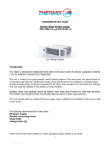
7. Set the fan speed control to the desired
position. Note: Not applicable if tted with a
Proportional Heat Output Controller (PHOC).
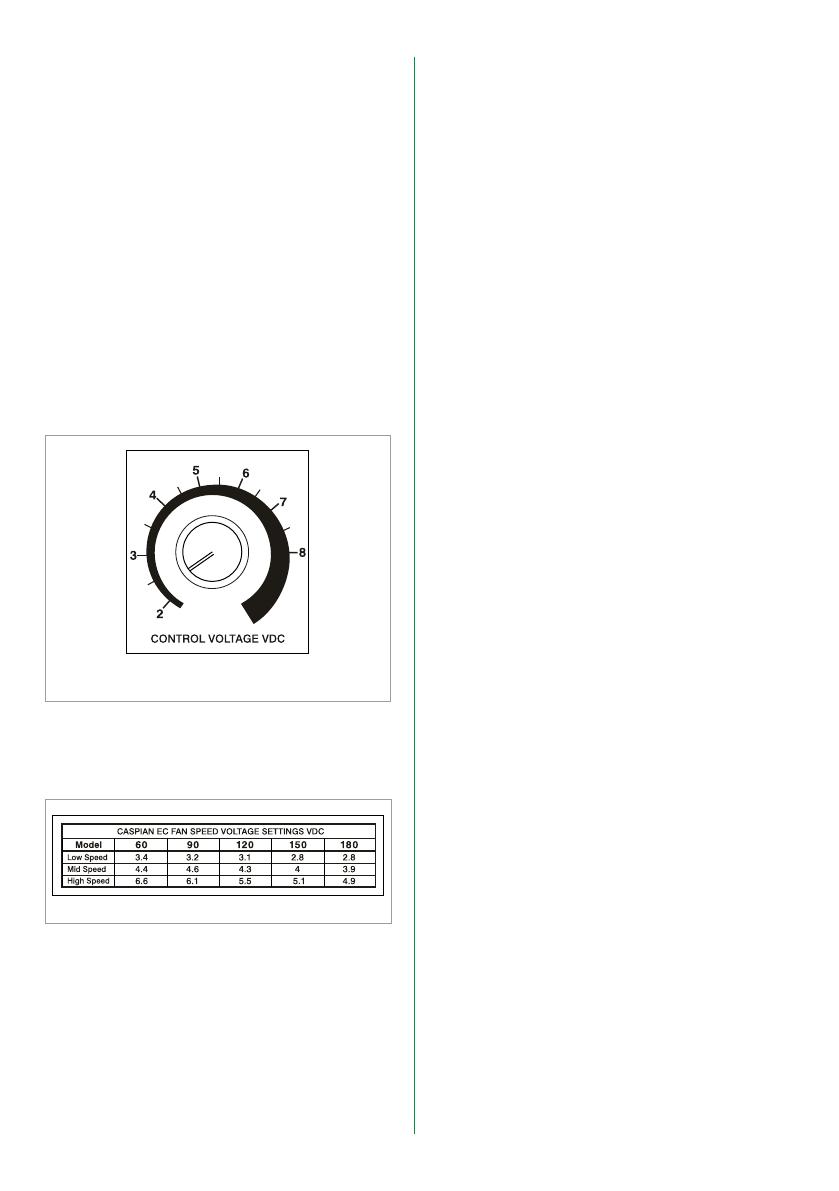
8. Set the dial to the speed required by
referencing the table included with the
product and shown below.
9. Lift up and close front access panel, ensure
this is secure and locked in place with
keys provided.
10. Please leave this Installation & User Guide with
the user for future reference.
Heating operation
Ensure the central heating system is ON.
Switch on the power supply to the unit. Set
the thermostat control (if tted) to the desired
temperature. Providing the water temperature in
the central heating system is more than 38°C and
the thermostat (if tted) is calling for heat the
product will switch on.
It is recommended that the model chosen is
capable of maintaining the calculated heat loss
at medium heat output enabling the high speed
setting to be used for faster heat up and the low
speed for maintaining temperature.
Proportional Heat Output Controller (PHOC)
Fan speed settings label
Maintenance
Warning! Isolate from the electrical supply
before performing any work on the unit.
The internal air lter is removable for servicing.
To gain access to the lter unlock and lower the
front access panel, remove the 2 screws from the
lter enclosure panel and lift out. Carefully lift out
and remove lter (see page 11). The lter should
be gently tapped to remove any accumulated
dust and vacuumed if necessary (approx. every
6 months). We recommend replacing the lters
approx. every 2 years depending on environmental
conditions.
The coil ns are delicate so take care and only use
a soft brush or vacuum cleaner to remove any dust
that may have accumulated.
The fan(s) and motors should not require servicing.
Please contact your supplier if damaged.
To replace lter use reverse the removal
instructions and ensure the lower front access
panel is securely locked.
Please note in the event of an engineer’s visit,
Smith’s Environmental Products Ltd reserve the
rights to apply a call-out charge should the fault
prove to be with the system or installation and not
the heater appliance.
14 | SmithsEP.co.uk | Issue 001 - July 2020
Fault nding
Fault Checking/Solution
The fan does not run on any speed setting
Check the power supply is switched ON
Check the fuse in the fused spur
Check the wiring at the fused spur
If thermostat is tted ensure it is calling for heat
Check the central heating is switched ON
Vent any trapped air from the system (with the heating system turned OFF)
No heat output
Check ow and return pipes are hot
Vent any trapped air from the system (with the heating system turned OFF)
Check the central heating is switched ON
If a thermostat is tted ensure it is calling for heat
Balance the central heating system if installed on the same circuit as panel
radiators and increase the circulating pump speed if required
Increase the boiler water temperature
Providing the power supply is switched on the room thermostat (if tted) is calling for heat the heater will
switch on and off automatically with the central heating system.
In the event of any difculty, please contact us on +44 (0) 1245 324560.
It will be helpful if you do not disconnect the heater from the central heating system.
Spares
Model
Component 60 90 120 150 180
Filter x 1 03-6015 03-6016 03-6017 03-6041 03-6043
Fan 06-0321 x 1 06-0321 x 2 06-0321 x 2 06-0321 x 3 06-0321 x 4
Coil 02-0301 02-0303 02-0304 02-0343 02-0382
See the table below to nd the product code for any spares that maybe required for your Caspian product.
Smith’s offer a range of accessories which can be
used in conjunction with this product. This includes:
Remote Room Thermostats (wired and wireless
inc tamper proof option)
Remote (wired) room thermostat Siemens
speed and temperature control
Wall mounted control switch
Adjustable low temperature cut-out (LTC)
Plinth (for oor standing application)
Caspian linking kits (EC only)
External control harness (EC only)
Proportional heat output controller (PHOC)
Thermostat T1
Flexible hoses and quick connector kits
For further information on accessories or spares
please contact either your supplier or Smith’s
Environmental Products Ltd or visit
www.SmithsEP.co.uk
Accessories
Issue 001 - July 2020 | SmithsEP.co.uk | 15
Registering your product
Thank you for purchasing a Smith’s product. It has
been designed and manufactured to the highest
quality standards to ensure it gives you efcient
and trouble-free service for many years. We are
committed to achieving the highest standards and
our faith is supported by a free parts and labour
guarantee with every product.
For more information on the warranty period
for this product please visit our website
smithsep.co.uk/product-registration/
This gives you the peace of mind that in the
unlikely event of product failure, we will repair
or replace the product completely free of charge
providing the product has been installed, used and
maintained in accordance with the instructions.
Your statutory rights are not affected by this
warranty.
It is important to register as soon as possible
online at: smithsep.co.uk/product-registration/.
This will ensure you will receive prompt and
efcient service if your product requires attention
within the warranty period. If you do not register
your product, you will be required to produce
proof of purchase prior to receiving service.
For more details please visit our website:
SmithsEP.co.uk
Disposal
As part of the policy of continuous product
improvement, Smith’s Environmental Products LTD
reserves the right to alter specication without
prior notice.
Products with this symbol (crossed out wheelie
bin) cannot be disposed as household waste.
Old electrical and electronic equipment must be
recycled at a facility capable of handling these
products and their waste by-products. If you are
purchasing replacement equipment your retailer
may offer a ‘take back’ scheme, or will be able to
give details of the nearest approved authorised
treatment facility. Proper recycling and waste
disposal will help conserve resources whilst
preventing detrimental effects on our health
and the environment.
WEEE Registered Code: WEE/ED0093VW
After sales
If you experience any problems with the use of
your product, please contact our after-sales ofce
+44 (0) 1245 324560.
For product information, customer services or
sales support call us on +44 (0) 1245 324900
For the Republic of Ireland, contact MT Agencies
on 01 864 3363
Sales: sales@SmithsEP.co.uk
General information: info@SmithsEP.co.uk
Smith’s Environmental Products Ltd
Blackall Industrial Estate, South Woodham Ferrers,
Chelmsford, Essex CM3 5UW
SmithsEP.co.uk
@SmithsEP_UK
#ThinkSmiths
Approved CQS ISO
9001:2015
Certificate No. EM2001002
ISO 14001
ISO 14001
ISO 14001
16 | SmithsEP.co.uk | Issue 001 - July 2020
To view the full product information
download the datasheet at:
www.SmithsEP.co.uk
For product information, customer services or
sales support call us on +44 (0) 1245 324900
For the Republic of Ireland, contact MT Agencies
on 01 864 3363
Sales: sales@SmithsEP.co.uk
General information: info@SmithsEP.co.uk
Smith’s Environmental Products Ltd
Blackall Industrial Estate, South Woodham Ferrers,
Chelmsford, Essex CM3 5UW
SmithsEP.co.uk
@SmithsEP_UK
#ThinkSmiths
Issue 001 | July 2020
Happy to help
Smith’s Environmental Products Ltd is one of the
leading manufacturers of heating and cooling
products in the UK. We are committed to
achieving the highest standards and our faith is
supported by a free parts and labour guarantee
with every product (see our website for more
information). Our customer service is second to
none and we are happy to offer any help and
guidance that you might need.
Stockists
All products are available nationally from Builders’
Merchants, Plumbers’ Merchants, Heating
Equipment Distributors and Kitchen Equipment
Distributors. In the event of difculty, please
contact us or visit our website SmithsEP.co.uk for
details of your nearest stockist.
Information and advice
Full technical specications and list prices is
available to download from our website or in
hard copy from our ofce. Also available on our
website are price lists, individual product data
sheets, installation & user guides, where to buy,
who to contact and a media centre.
Alternatively contact our ofce 9.00am to 5.00pm
Monday to Friday.
As part our commitment to continuous
improvement Smith’s Environmental Products may
change the specifications of its products without
prior notification or public announcement.
All descriptions, illustrations, drawings and
specifications in this publication present only
general particulars and shall not form part of
any contract. All dimensions are in mm unless
otherwise stated. Please visit the website for the
most up to date information.
Smith’s, providing comfort for the built environment
  • Page 1 1
  • Page 2 2
  • Page 3 3
  • Page 4 4
  • Page 5 5
  • Page 6 6
  • Page 7 7
  • Page 8 8
  • Page 9 9
  • Page 10 10
  • Page 11 11
  • Page 12 12
  • Page 13 13
  • Page 14 14
  • Page 15 15
  • Page 16 16

Swann Smith's Caspian EC 60 Installation and User Manual

Type
Installation and User Manual

Ask a question and I''ll find the answer in the document

Finding information in a document is now easier with AI