Page is loading ...

CE 0694 SF 14 - RAD - ING - MAN.UT - 0904B - MIR7VD6FLC
Technical specification RADIANT BRUCIATORI S.p.A. Montelabbate (PU) ITALY
User Manual
for models
SF 14
Gas Water Heater


USER INSTRUCTIONS
1
WATER HEATER OPERATING INSTRUCTIONS
Make sure that the authorised technician who tested the boiler has stamped the guarantee booklet.
The installation, first start-up, regulation and maintenance operations must be carried out exclusively by qualified
personnel (e.g. Radiant authorised Service Centres). Incorrect installation can cause damage to property and
injury to persons or animals, for which the manufacturer will not be held responsible.
During the installation, the technician must carry out the following checks:
■ The data on the data plate must correspond to that of the mains supply networks (gas, electricity, water);
■ The water heater must be regulated according to its designed use and performance;
■ The flue gas exhaust and combustion air intake system must be correctly installed and operational;
■ The exhaust gas discharge and ventilation systems must comply with the requirements of national and local
standards regardless of whether the water heater is installed indoors, outdoors or in its own cabinet (see
section “Reference standards”).
General Warnings
If there is any doubt as to whether the appliance has been tested by an authorised technician, do not attempt
to start it. All maintenance and gas conversion operations MUST BE CARRIED OUT BY PROFESSIONALLY
QUALIFIED PERSONNEL, registered in accordance with current legislation.
Make sure that the requirements relating to the air intake and ventilation of the room in which the
water heater is to be installed have been complied with;
The water heater can be installed outdoors in a partially protected location, in accordance with
current standards and where the minimum external temperature does not fall below –10°C. The
manufacturer will not be held responsible for installation in locations where the temperature falls to
below –10°C;
Should any part of the water heater freeze-up, do not attempt to light it under any circumstances, but instead
call the Service Centre immediately;
Do not obstruct the ventilation openings in rooms where there are gas-burning appliances installed (boiler,
cooker, etc.);
The natural draught water heaters are equipped of a control device which permit the correct exhaust fumes
discharge; The device permit the maximal safety during the water heater functioning.

USER INSTRUCTIONS
2
If you smell gas …
DO NOT ACTIVATE ANY ELECTRIC SWITCHES, TELEPHONES OR ANY OTHER DEVICE THAT MAY
GENERATE ELECTRICAL DISCHARGES OR SPARKS.
OPEN DOORS AND WINDOWS IMMEDIATELY TO CREATE A CURRENT OF AIR THAT WILL RAPIDLY
CLEAR THE ROOM.
CLOSE ALL GAS TAPS AND VALVES.
CALL FOR PROFESSIONALLY QUALIFIED TECHNICAL ASSISTANCE.
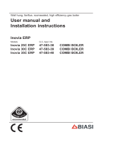
Water heater controls – Control panel
1.
ON/OFF SWITCH.
2. MIN – MAX OUTPUT ADJUSTMENT KNOB.
3. D.H.W TEMPERATURE CONTROL KNOB
4. STABLE LIGHT: POWER ON
FLASHING LIGHT: FLAME ON
5. FLASHING LIGHT: FLUE SAFETY THERMOSTAT MALFUNCTION( Mod. S 14)
AIR PRESSURE SWITCH (Mod. SF 14)
6. FLASHING LIGHT: FLAME LOCK OUT
7. FLASHING LIGHT: HIGH LIMIT SAFETY THERMOSTAT LOCK OUT
8. FLASHING LIGHT: D. H.W. SENSOR/SOLAR PANEL SENSOR FAILURE
9. TERMINAL BLOCK FOR ELECTRIC WIRINGS
12 9
5
4
6
8
7
3
ON
40°
45°
50°
55°
60°

USER INSTRUCTIONS
3
Starting up the water heater
Open the gas tap located under the
water heater;
Switch on the water heater by
placing the ON/OFF switch (1) in
the ON position (fig. 1 led 4 - stable
light).
The water heater will start
automatically after the D.H.W
request (fig. 1, led 4 - flashing light);
Check that there are no flashing led
on the display, if flashing lights
appear call an authorised Service
Centre;
D.H.W temperature control
The domestic hot water temperature is regulated by knob 3 (fig.1);
Rotating the knob anticlockwise reduces the temperature.
Rotating the knob clockwise increases the temperature.
The range of temperature settings for the domestic hot water runs from a minimum of 35°C to a maximum of
60°C
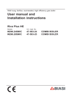
Min-Max output adjustment
The output of the water heater is regulated by knob 2 (fig. 2);
Rotating the knob anticlockwise reduces the water heater output.
Rotating the knob clockwise increases the water heater output.
The output setting range is from a minimum of 8.5 Kw to a maximum of 24 Kw.
Regulate the knob 2 (fig. 2) in a comfort condition in relation to the D.H.W flow rate and temperature inlet (fig.
2). Ex: with a flow rate of 10 lt/min. and a cold water inlet temperature of 10°C, position the knob indicator on
the red graduated scale.
60°
55°
50°
45°
40°
ON
4
1
5
Fig. 1
2 3
6 7 8

USER INSTRUCTIONS
4
Diagnostics – Error codes:
This paragraph contains a list of error codes that the water heater may generate on the display together with the
relative indications and operations that the user can carry out to reset the water heater.
If the problem re-occurs after the following actions have been taken, call an authorised Service Centre.
Ionisation block
Led 6 lit continuously on the display (pag. 3 fig. 1).
Check that the gas valve on the water heater and gas meter are open and that there is gas in the mains supply
(or in the tank).
Switch off then switch on the appliance using switch 1 on the control panel;
When the error code on the display disappears, the water heater will restart.
If the problem persists, Call the Service Centre.
Safety Thermostat tripped
Led 7 lit continuously on the display (pag. 3 fig. 1).
Switch off then switch on the appliance using switch 1 on the control panel;
If the problem persists, Call the Service Centre.
Flue thermostat tripped (Mod. S 14)
Led 5 lit continuously on the display (pag. 3 fig. 1).
Switch off then switch on the appliance using switch 1 on the control panel;
If the problem persists, Call the Service Centre.
Air pressure switch (Mod. SF 14)
Led 5 lit continuously on the display (pag. 3 fig. 1).
Switch off then switch on the appliance using switch 1 on the control panel;
If the problem persists, Call the Service Centre.
D.H.W Sensor malfunction
Led 8 lit continuously on the display (pag. 3 fig. 1).
If the problem persists, Call the Service Centre.
Attention! When the appliance is no longer required for use, switch off the main power supply, to switch all
electrical components off (circulating pump, burner etc.) and draining the water heater.


RADIANT BRUCIATORI s.p.a.
Via Pantanelli, 164/166 - 61025 Loc. Montelabbate (PU)
Tel. +39 0721 9079.1 • fax. +39 0721 9079279
e-mail: tecnico@radiant • Internet: http://www.radiant.it
THE TECHNICAL DATA AND MEASUREMENTS ARE PROVIDED FOR INFORMATION
PURPOSES ONLY AND ARE NOT BINDING. THE COMPANY RESERVES THE RIGHT
TO APPLY VARIATIONS WITHOUT PRIOR NOTIFICATION. NEITHER WILL THE
COMPANY BE HELD RESPONSIBLE FOR ANY INACCURACIES IN THIS HANDBOOK
DERIVING FROM PRINTING OR TRANSLATION ERRORS. E+OEALL RIGHTS
RESERVED. NO PART OF THIS DOCUMENT MAY BE REPRODUCED, MEMORISED
IN ANY FILING SYSTEMS OR TRANSMITTED IN ANY FORM WHATSOEVER,
INCLUDING ELECTRONIC, MECHANICAL, PHOTOCOPIES, RECORDINGS OR ANY
OTHER MEANS WITHOUT THE COMPANY’S PRIOR WRITTEN APPROVAL.
/