Page is loading ...

TIG 200 AC/DC WELDER
ASSEMBLY & OPERATING INSTRUCTIONS
Part #12746
© Copyright 2014 Easthill Group, Inc. Instruction part #12746Q Rev. 2/14
If you have any questions about the use of this product, please contact
The Eastwood Technical Assistance Service Department: 800.544.5118 >> email: techelp@eastwood.com
PDF version of this manual is available online >> eastwood.com/12746manual
The Eastwood Company 263 Shoemaker Road, Pottstown, PA 19464, USA
US and Canada: 800.345.1178 Outside US: 610.718.8335
Fax: 610.323.6268 eastwood.com

SPECIFICATIONS
TIG Welding is the most controllable, efficient and most versatile method of welding many metals including steel, stainless steel,
aluminum and more. Your Eastwood TIG 200 Welder with High-Frequency Inverter Technology is capable of welding thin or heavy
gauge steel and aluminum with precision and ease. The Voltage self-sensing circuitry automatically detects a power source range of
110 to 240 Volts and delivers from 10 up to 200 Amps of AC or DC current at super-high frequency with the added advantage of a light
weight unit. The included foot pedal provides the operator with the precise Amperage control required when welding. A high frequency
start feature guarantees an instant arc strike with no tungsten contamination.
STATEMENT OF LIMITED WARRANTY
The Eastwood Company (hereinafter “Eastwood”) warrants to the end user (purchaser) of all new welding and cutting equipment (collectively called the “products”) that it will
be free of defects in workmanship and material. This warranty is void if the equipment has been subjected to improper installation, improper care or abnormal operations.
WARRANTY PERIOD:
All warranty periods begin on the date of purchase from Eastwood. Warranty Periods are listed below, along with the products covered during those warranty periods:
3 Year Warranty on Material, Workmanship, and Defects:
• Eastwood TIG 200 AC/DC Welder
Items not covered under this warranty: Collets, collet bodies, tungsten, nozzles, and ground clamp and cable.
All other components are covered by the warranty and will be repaired or replaced at the discretion of Eastwood.
2 Years:
• All Welding Helmets.
CONDITIONS OF WARRANTY TO OBTAIN WARRANTY COVERAGE:
Purchaser must first contact Eastwood at 1-800-345-1178 for an RMA# before Eastwood will accept any welder returns.
Final determination of warranty on welding and cutting equipment will be made by Eastwood.
WARRANTY REPAIR:
If Eastwood confirms the existence of a defect covered under this warranty plan, Eastwood will determine whether repair or replacement is the most suitable option
to rectify the defect. At Eastwood’s request, the purchaser must return, to Eastwood, any products claimed defective under Eastwood’s warranty.
FREIGHT COSTS:
The purchaser is responsible for shipment to and from Eastwood.
WARRANTY LIMITATIONS:
EASTWOOD WILL NOT ACCEPT RESPONSIBILITY OR LIABILITY FOR REPAIRS UNLESS MADE BY EASTWOOD. EASTWOOD’S LIABILITY UNDER THIS WARRANTY SHALL NOT
EXCEED THE COST OF CORRECTING THE DEFECT OF THE EASTWOOD PRODUCT. EASTWOOD WILL NOT BE LIABLE FOR INCIDENTAL OR CONSEQUENTIAL DAMAGES (SUCH
AS LOSS OF BUSINESS, ETC.) CAUSED BY THE DEFECT OR THE TIME INVOLVED TO CORRECT THE DEFECT. THIS WRITTEN WARRANTY IS THE ONLY EXPRESS WARRANTY
PROVIDED BY EASTWOOD WITH RESPECT TO ITS PRODUCTS. WARRANTIES IMPLIED BY LAW SUCH AS THE WARRANTY OF MERCHANTABILITY ARE LIMITED TO THE
DURATION OF THIS LIMITED WARRANTY FOR THE EQUIPMENT INVOLVED. THIS WARRANTY GIVES THE PURCHASER SPECIFIC LEGAL RIGHTS.
THE PURCHASER MAY ALSO HAVE OTHER RIGHTS WHICH VARY FROM STATE TO STATE.
DUTY CYCLE
The Rated Duty Cycle refers to the amount of welding that can be done within an amount of time. The Eastwood TIG 200 has a duty
cycle of 45% at 150 Amps. It is easiest to look at your welding time in blocks of 10 Minutes and the Duty Cycle being a percentage
of that 10 Minutes. If welding at 150 Amps with a 45% Duty Cycle, within a 10 Minute block of time you can weld for 4.5 Minutes
with 5.5 Minutes of cooling for the welder. To increase the Duty Cycle you can turn down the Amperage Output control. Going above
150 Amps will yield a lower duty cycle.
2 Eastwood Technical Assistance: 800.544.5118 >> techelp@eastwood.com To order parts and supplies: 800.345.1178 >> eastwood.com 15
Output
Amperage
Range
Maximum
Output No Load
Voltage
Input
Voltage
Rated
Duty
Cycle
Pre
Gas
Flow
Post
Gas
Flow
Weight
Overall
Dimensions
10-200 A
AC/DC
51 V DC
120 VAC
50-60 Hz
220 VAC
50-60 Hz
45%
@ 150 A
0.1-1.0 Sec 2-8 Sec 45 Lbs.
19.1” (486 mm) x
9.8” (248 mm) x
20.0” (508 mm)
NOTES

14 Eastwood Technical Assistance: 800.544.5118 >> techelp@eastwood.com To order parts and supplies: 800.345.1178 >> eastwood.com 3
READ INSTRUCTIONS!
Thoroughly read and understand this instruction manual before using the welder.
SAFETY INFORMATION
ELECTRIC SHOCK CAN KILL!
• Improper use of an electric welder can cause electric shock, injury and death! Read all precautions described
in this manual to reduce the possibility of electric shock.
• Do not touch any electrical components that may be live.
• Separate yourself from the welding circuit by using insulating mats to prevent contact from the work surface.
• Always wear dry, protective clothing and leather welding gloves and insulated footwear.
• Always operate the welder in a clean, dry, well ventilated area. Do not operate the welder in humid, wet, rainy or
poorly ventilated areas.
• Be sure that the work piece is properly supported and grounded prior to beginning an electric welding operation.
• The electrode and work (or ground) circuits are electrically “hot” when the welder is on. Do not touch these “hot”
parts with your bare skin or wet clothing.
• Disconnect from power supply before assembly, disassembly or maintenance of the torch or
replacement of consumable torch components such as electrodes and collets.
• Always attach the ground clamp to the piece to be welded and as close to the weld area as possible.
This will give the least resistance and best weld.
FUMES AND WELDING GASES CAN BE DANGEROUS!
• Do not breathe fumes that are produced by the welding operation. These fumes are dangerous. Keep your head
and face out of welding fumes.
• Always work in a properly ventilated area. Wearing an OSHA-approved respirator when welding is recommended!
• Never weld coated materials including but not limited to: cadmium and galvanized plating or lead based paints.
• Refer to the MSDS (Material Safety Data Sheet) for any consumables or materials used during welding for
additional safety instructions.
WELDING SPARKS CAN CAUSE FIRE OR EXPLOSION!
• Do not operate electric arc welder in areas where flammable or explosive vapors are present.
• Always keep a fire extinguisher nearby while welding.
• Use welding blankets to protect painted surfaces, upholstery, dash boards, engines, etc.
• Ensure power supply has properly rated wiring to handle power usage.
• Do not use on or near combustible surfaces.
• Remove all flammable items within 35 feet of the welding area.
• Do not attempt to use on frozen or water filled pipes.
NOTES

4 Eastwood Technical Assistance: 800.544.5118 >> techelp@eastwood.com To order parts and supplies: 800.345.1178 >> eastwood.com 13
ARC RAYS CAN BURN!
• Use a shield with the proper filter (a minimum of #13) to protect your eyes from sparks and the rays of the arc
when welding or when observing open arc welding. (see ANSI Z49.1 and Z87.1 for safety standards)
• Use suitable clothing made from durable flame-resistant material to protect your skin. Protect nearby individuals
with a non-flammable barrier.
• Wear safety glasses with side shields under your welding helmet.
• If other persons are in the welding area, use welding screens to protect them from sparks and arc rays.
HOT METAL WILL BURN!
• Electric welding operations cause sparks and heat metal to temperatures that will cause severe burns!
• Use protective gloves and clothing when performing any welding operations. Always wear long pants,
long-sleeved shirts and leather welding gloves.
• Make sure that all persons in the welding area are protected from heat, sparks and ultraviolet rays.
Use additional face shields and flame resistant barriers as needed.
• Never touch work piece until it has completely cooled.
ELECTROMAGNETIC FIELDS MAY BE DANGEROUS!
• The electromagnetic field that is generated during arc welding may interfere with and damage sensitive electrical
and electronic devices such as cardiac pacemakers, cell phones, computers, cameras, and watches. Keep this
equipment at least 30 ft. from welding area.
• Exposure to electromagnetic fields while welding may have other health effects which are not known.
FLYING METAL CHIPS CAN CAUSE INJURY!
• Welding, brushing, hammering, chipping, and grinding can cause flying metal chips and sparks.
• To prevent injury wear approved safety glasses.
MAGNETIC FIELDS CAN AFFECT PACEMAKERS!
Anyone with a pacemaker should consult with their physician prior to performing any electric welding operations.
SAFETY INFORMATION
NOTICE!
Do not touch the electrode with the unit turned “ON”. Turn the unit “OFF” and unplug from power source before
changing electrodes and collet parts, or cleaning the nozzle.
ACCESSORIES
TIG WIRE & TUNGSTEN:
• #12253 – ER70S-2 Steel TIG Wire 1/16-36”
• #12254 – ER70S-2 Steel TIG Wire 3/32-36”
• #12375 – 4043 Aluminum TIG Wire 1/16-36”
• #12376 – 4043 Aluminum TIG Wire 3/32-36”
• #12463 – 308L Stainless TIG Wire 1/16-36”
• #12464 – 308L Stainless TIG Wire 3/32-36”
• #20176 – E
3
Purple Tungsten 1/16-7” 2pc
• #20177 – E
3
Purple Tungsten 3/32-7” 2pc
NOTE: E
3
Purple Tungsten is universal and can be used on steel, aluminum, and stainless steel.
REPLACEMENT ITEMS:
• #13483 – TIG 200 Collet Body (1.6mm; 1/16”)
• #13484 – TIG 200 Collet Body (2.4mm; 3/32”)
• #12822 – TIG 200 Collet (1.6mm; 1/16”)
• #12824 – TIG 200 Collet (2.4mm; 3/32”)
• #12825 – TIG 200 Long Back Cap
• #12819 – TIG 200 Gas Nozzle (9.8mm; 3/8”)
• #12821 – TIG 200 Gas Nozzle (11.2mm; 1/2”)
• #13953 – TIG Accessory Kit
OTHER WELDING ACCESSORIES:
• #11947 – Flap Disc 60 Grit 4.5” Diameter 7/8” Hole
• #12590 – Welding Gloves Large
• #12589 – Welding Gloves Medium
• #12099 – Auto Darkening Welding Helmet
• #19079S – Stainless Steel Brush
• # 51139 – Copper 3 x 3 Welders Helper Set
• #50739 – Master Welder’s Helper Panel Holding Kit
• #19015 – Welders Pliers
• #12762L, XL, XXL – Welding Jacket
• #11616 – TIG 200 Welding Cart

12 Eastwood Technical Assistance: 800.544.5118 >> techelp@eastwood.com To order parts and supplies: 800.345.1178 >> eastwood.com 5
REQUIRED ITEMS
Before you begin using the Eastwood TIG Welding System, make sure you have the following:
• Our TIG 200 is supplied with the popular NEMA 50P plug, requiring a NEMA 50 receptacle. If a 220-240 VAC, 30 Amp outlet
is used a UL listed 30 Amp plug may be installed by a licensed and qualified electrician.
• The TIG 200 will also operate on a 110-120 VAC 20 Amp circuit. To operate on this voltage it is necessary to connect the included
adaptor cord to the plug hard wired to the TIG 200.
• A clean, safe, well-lit, dry and well-ventilated work area.
• A non-flammable, long sleeve shirt or jacket (Eastwood #12762L, XL, XXL).
• Heavy Duty Welding Gloves (#12590)
• An Auto Darkening Welding Mask (Eastwood #13203, #13212, #14425 or equivalent) to provide eye protection during
welding operations. NOTE: MUST be a #11 lens or darker.
• A compressed gas cylinder containing 100% Argon (must be used when TIG welding and is available at any welding supply facility).
• Dedicated stainless steel wire welding brush for each material to be welded.
• A dedicated fine grit synthetic stone grinding wheel or a Tungsten Sharpener.
POWER REQUIREMENTS
The Eastwood TIG 200 AC/DC is Voltage sensing; it will automatically operate on 110-120 VAC, 50/60 Hz., or 220-240 VAC, 50/60 Hz.
Eastwood recommends at a minimum a properly grounded 110-120 VAC 50/60Hz., 20 Amp circuit or 220-240 VAC 50/60Hz., 30 Amp
circuit.
BEFORE YOU BEGIN
Remove all items from the box. Compare with list below to make sure unit is complete.
TROUBLESHOOTING
• #7 Gas Nozzle (7/16”)
• #6 Gas Nozzle (3/8”)
• #5 Gas Nozzle (5/16”)
• Long Back Cap
• Short Back Cap
• 3/32” Collet Body
• 3/32” Collet
• 1/16” Collet
• 1/16” Red (Thoriated Tungsten)
• TIG 200 AC/DC Welder with NEMA50-P Plug
• Shielding Gas Regulator
• Shielding Gas Hose
• Ground Cable with Clamp (10’)
• TIG Torch (17 Series) which accepts industry
standard cups, collets and collet bodies (14’)
• Foot Pedal for Amperage Control
• 110-120 VAC to 220-240 VAC Adaptor Plug
• Instruction Manual
• Hand Held Shield
• Hammer/Brush

6 Eastwood Technical Assistance: 800.544.5118 >> techelp@eastwood.com To order parts and supplies: 800.345.1178 >> eastwood.com 11
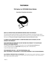
COMPONENTS AND CONTROLS
1. Power Switch – The Power Switch also serves as the overload Circuit Breaker
and is located at the right of the rear panel (Fig. C).
2. Amperage (Front Panel) – Set the Output Amperage Knob marked “A” (Fig. A)
located at upper left of the top panel to an appropriate setting based on the thickness
and type of the metal being welded. (Refer to Data Chart for actual settings.)
3. Amperage (Foot Pedal) – Same operation as the panel control but is used while
the foot pedal is in use (Fig. B).
4. Clearance Effect – The Clearance Effect Knob (Fig. A) is located at the
upper right of the top panel. Clearance Effect will control how much cleaning
versus penetration occurs. The more negative the value will result in greater
penetration and less cleaning and the more positive the value will result in less
penetration but greater cleaning.
5. Pre Flow – The Pre Flow Knob located at the lower left of the top panel (Fig. A)
controls the time (in seconds) that the shielding gas starts to fl ow after the trigger or
foot pedal is press before the arc starts. (Refer to Data Chart for actual settings.)
6. Post Flow – The Post Flow Knob located at the lower right of the top panel (Fig. A)
controls the time (in seconds) that the shielding gas continues to fl ow after the
trigger or foot pedal is released. (Refer to Data Chart for actual settings.)
7. Gas Flow – The included regulator limits the shielding gas fl ow from the bottle
and also displays how much gas is left in the bottle. The Gas Flow Indicator
Gauge is located on the left side and is generally set between 12 to 21 SCFH.
(Refer to Data Chart for actual settings.) This is explained in further detail in
the Preparing to Weld section of this manual. The gauge on the right indicates the
pressure left in the tank.
8. AC/DC – The DC setting is used for welding steel and stainless steel while the
AC setting is used for welding aluminum (Fig. A). (Refer to Data Chart for
actual settings.)
9. Foot Pedal/Panel Control – The Foot Pedal/Panel Control selection switch
is located at the upper right of the top panel and when set in the ‘Foot Pedal’
position, the Foot Pedal control is activated. When set to the ‘Panel Control’
position, the Torch Trigger is activated (Fig. A).
10. Torch Switch – The switch on the torch (Fig. D) controls starting and stopping
the arc. When using the torch switch the Amperage is set on the adjustment knob
on the front panel of the welder.
11. Foot Pedal – The foot pedal is for starting and stopping the arc as well as controlling
the Amperage during the weld. When using the foot pedal the Amperage is set by
the adjustment knob on the side of the foot pedal (Fig. B).
DATA CHART (ALSO LOCATED ON TOP OF WELDER)
FIG. A
FIG. B
FIG. C
FIG. D
MATERIAL
MATERIAL
THICKNESS
POLARITY AMPERAGE TUNGSTEN COLOR
TUNGSTEN
DIA.
FILLER
METAL
FILLER
METAL DIA.
PRE FLOW
(sec)
POST FLOW
(sec)
TORCH CUP
SIZE
GAS FLOW
RATE
(scfh)
CLEARANCE
EFFECT
Aluminum 1/16”AC55-75 1/16” 40431/16” 0.451/4 - 3/8” 15 -3 to 0
Aluminum 3/32”AC70-100 1/16” 40431/16” 0.451/4 - 3/8” 15 -3 to 0
Aluminum 1/8” AC 90-140 3/32” 40433/32” 0.463/8 - 7/16”17-3 to 0
Aluminum 3/16”AC125-180 Green, Red, Purple 3/32” 40433/32” 0.467/16 - 1/2” 21 -3 to 0
Steel1/16” DC-45-80 1/16”ER70S-2 1/16”0.4 51/4 - 3/8” 12 0
Steel3/32” DC-70-1101/16” ER70S-21/16” 0.451/4 - 3/8” 12 0
Steel1/8”DC- 75-125 1/16”ER70S-2 3/32”0.4 61/4 - 3/8” 12 0
Steel3/16” DC-110-200 3/32”ER70S-2 1/8” 0.461/4 - 3/8” 14 0
Stainless Steel1/16” DC-50-90 1/16”ER308/308L 1/16”0.4 51/4 - 3/8” 12 0
Stainless Steel3/32” DC-80-1201/16” ER308/308L 1/16”0.4 51/4 - 3/8” 12 0
Stainless Steel1/8”DC- 85-140 1/16”ER308/308L 3/32”0.4 61/4 - 3/8” 12 0
Stainless Steel3/16” DC-125-200 3/32”ER308/308L 1/8” 0.461/4 - 3/8” 14 0
Gray, Red, White, Purple
Green, Red, Purple
Green, Red, Purple
Green, Red, Purple
Gray, Red, White, Purple
Gray, Red, White, Pu
rple
Gray, Red, White, Purple
Gray, Red, White, Purple
Gray, Red, White, Purple
Gray, Red, White, Purple
Gray, Red, White, Purple
TROUBLESHOOTING
Problem Cause Fix
IncompleteCircuit
CheckGroundconnection.Makesurethatthegroundisona
freshlycleanedsurfaceandclosetotheweldingarea.Itis
suggestedtoweldtowardsthegroundconnection.
IncorrectTungsten
Consultchartforpropertungstenforthebasemetalbeing
welded.InmostcasesPureTungstenwillbeforaluminum
andThoriatedwillbeforsteel.
Noshieldinggas
Makesuretheshieldinggascylinderisturnedalltheway
openandsetatthecorrectflowrate.
WrongPolarity
Makesurepolarityissetforthecorrectmaterial.ACshould
beusedforaluminumwhileDCshouldbeusedforsteel.
Poorlypreppedtungsten Followguidelinesforpreppingtungsten.
PoorGasFlow
Adjusttheflowrateoftheshieldinggas(refertosettings
chart).Checkforloosefittingswheregascouldbeleaking.
ContaminatedTungsten
Removetungstenfromtorchandbreakoffcontaminated
sectionandresharpen.
Incorrectarclength
Makesurethetungstenisheld1/8to1/4inchoffthework
piece.
Incompletecircuit
CheckGroundconnection.Makesurethatthegroundisona
freshlycleanedsurfaceandclosetotheweldingarea.Itis
suggestedtoweldtowardsthegroundconnection.
Contaminatedbasemetal
Cleanbasemetalmakingsuretoremoveanyoil,debris,
coatings,ormoisture.Ifbasemetalisaluminummakesureall
oftheoxideisremovedusingeitheradedicatedstainless
brushorflapwheel.
IncorrectClearanceEffect(AC)
ShiftmorenegativeontheClearanceEffectknobsolessheat
isgoingintothetungsten.
PoorGasFlow
Adjusttheflowrateoftheshieldinggas(refertosettings
chart).Checkforloosefittingswheregascouldbeleaking.
Contaminatedfillermetal
Cleanfillermetalmakingsuretoremoveanyoil,debris,or
moisture.
Contaminatedbasemetal
Cleanbasemetalmakingsuretoremoveanyoil,debris,
coatings,ormoisture.
PoorShielding
Makesuretobeinanareawithnowindandwithanyfans
turnedoff.Windorfanswillblowtheshieldinggasawayfrom
theweldcausingporosity.
IncorrectTungstenStickOut
Adjustthetungstensothat1/8to1/4inisstickingoutofthe
collet.
ContaminatedTungsten
Removetungstenfromtorchandbreakoffcontaminated
sectionandresharpen.
ContaminatedFillerMetal
Cleanfillermetalmakingsuretoremoveanyoil,debris,or
moisture.
ContaminatedBaseMetal
Cleanbasemetalmakingsuretoremoveanyoil,debris,
coatings,ormoisture.Ifbasemetalisaluminummakesureall
oftheoxideisremovedusingeitheradedicatedstainless
brushorflapwheel.
PoorGasFlow
Adjusttheflowrateoftheshieldinggas(refertosettings
chart).Checkforloosefittingswheregascouldbeleaking.
ImproperClearanceEffect(AC)
ShiftmorenegativeontheClearanceEffectknobsolessheat
isgoingintothetungsten.
WrongSizeTungsten Increasetungstendiameter.Refertochartforpropersizing.
Notenoughpostflow Increasepostflowtimetoallowthegastocoolthetungsten.
IncorrectShieldingGas Onlyuse100%ArgonwhenTIGWelding.
LowVoltage
Voltagesettingistoolowformaterial/thickness.Increaseas
neededandreferencechartonwelder.
IncorrectClearanceEffect(AC)
Shifttheclearanceeffectmoretothenegativesideasthiswill
transfermoreheattothematerialbeingwelded.
PoorPenetration(Steel)
LowVoltage
Voltagesettingistoolowformaterial/thickness.Increaseas
neededandreferencechartonwelder.
TungstenContaminated
ContactofTungstenwithBase
Metal
Keeptungsten1/8to1/4inchfromthebasemetal.If
tungstencomesincontactbreakoffendandresharpen
immediately.
PoorWeldAppearance
Incorrectpositioning
Theanglebetweenthefillermetalandthetorchmustbeless
than90degreesotherwisethefillermetalwillprematurely
meltandgloboffcausingpoorweldappearance.
InsuficcientShielding
Keepthetorchonthebasemetalwhilethepostflow
shieldinggasflowstoprotectandcoolthemetaland
tungsten.
NotEnoughFillerMaterial
Reducecurrentwithpedelandaddmorefilleratendofweld.
Itmayalsobebenficaltobacksteptoensurenocraterwill
form.
Toomuchheatinmaterial Reduceheatandallowmoretimebetweenpasses.
BaseMetalisabsorbingtoomuch
heat
Preheatbasemetal(consultweldingcodesforrequirments)
IncorrectFillerWire Reducefillerwiresize.
InsufficentClamping Clampworkpiecetightlyandweldwhileclampsareinplace.
InsufficentTackWelds Addmoretackweldsuntilrigidityandstiffnessisdeveloped.
TooMuchHeatinMaterial
Toreduceheatitisbesttospreadtheweldingoutaroundthe
area.Thiscanbedonebyusingstitchweldingtechniques,
alternatingsides,and/ortakingyourtimeandallowingthe
piecestocoolbetweenpasses.
Arcistriggeredbutwillnotstart
Porosityinweldbead
CraterintheEndoftheWeldBead
WeldBeadisCracking
MaterialisWarping
PoorPenetration(Aluminum)
Arcwandersanditishardtoconcentrate
heatinaspecificarea
Contaminationinweldbead
MeltingTungsten

10 Eastwood Technical Assistance: 800.544.5118 >> techelp@eastwood.com To order parts and supplies: 800.345.1178 >> eastwood.com 7
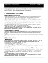
SETUP
SHIELDING GAS CONNECTION
A Shielding Gas Bottle is not included with your Eastwood TIG 200 but is necessary
while TIG welding. A Shielding Gas Bottle can be bought at most local Welding
Supply Stores. Eastwood recommends the use of 100% Argon shielding gas
when TIG welding Steel, Aluminum, and Stainless Steel.
1. Place the Eastwood TIG 200 in its dedicated area or on a welding cart.
2. Secure your Shielding Gas Bottle to a stationary object or mount to your
welding cart if it is equipped to hold one so that the cylinder cannot fall over.
3. Remove the cap from the Shielding Gas Bottle.
4. Insert the large brass male fi tting on the Shielding Gas Regulator into
the female fi tting on the Shielding Gas Bottle (Fig. E). NOTE: Do not use
White Tefl on Tape on this connection as it is a tapered thread and does not
require it, if you have a leak check for burrs or dirt in the threads. If the leak
persists, use gas type sealing tape.
5. Tighten the fi tting with a wrench till snug, do not over tighten.
6. Connect either end of the Gas Line included with your Eastwood TIG 200 to
the fi tting on the regulator and tighten with a wrench until snug.
7. Connect the other end of the gas line to the fi tting on the rear of the
Eastwood TIG 200 and tighten with a wrench until snug (Fig. F).
TORCH CONNECTION
1. Install the plastic connection cover onto the brass torch fi tting on the
torch cable.
2. Connect the female brass fi tting on the torch cable to the male brass fi tting
on the welder (Fig. G).
3. Use a wrench and tighten until snug. DO NOT OVERTIGHTEN.
4. Connect the black 4 pin plug to the Torch Switch Connection as shown in (Fig.
G). (NOTE: Omit this step if you will be using the foot pedal for Amperage
control.)
GROUND CABLE CONNECTION
1. Locate the Ground Cable and Clamp.
2. The Ground Cable connection is located at the far right of the front panel as
shown in (Fig. G). With the Key on the connector in the 12 O’clock position,
insert the connector and turn 180° clockwise to lock in the connector.
FOOT PEDAL CONNECTION
1. If you are going to be using the switch on the torch to start the welding arc,
omit this step.
2. Connect the Black 4 pin plug on the Foot Pedal to the Switch Connection as
shown in (Fig. G).
3. Connect the Metal 2 Pin Plug on the Foot Pedal to the Foot Pedal Connection
as shown in (Fig. G).
FIG. E
FIG. F
FIG. G
Ground
Cable
Torch
Switch/Foot
Pedal
Foot PedalGas Flow
Through
Power Cable
✓
✓
✓
✓
WELDING
IMPORTANT NOTE:
These instructions are intended only to provide the user with some familiarity
of the Eastwood TIG 200. TIG welding is a highly complex procedure with many
variables. If you have no experience with TIG welding; it is extremely important
to seek the advice of someone experienced in TIG welding for instruction, enroll
in a local technical school welding course or study a comprehensive how-to DVD
and obtain a good quality reference book on TIG welding as there is a moderate
learning curve necessary before achieving profi ciency in TIG Welding. Before
attempting to use this unit on an actual project or object of value, practice on
a similar material as there are many variables present and settings required
when TIG welding different metals such as steel or aluminum. It is also strongly
recommended that the user adhere to the American Welding Society guidelines,
codes and applications prior to producing welds where safety is affected.
1. Turn the Power Switch/Circuit Breaker to the on position.
2. Slowly open the gas cylinder valve. NOTE: Always open valve fully to avoid
shielding gas leakage.
3. Depress gun trigger switch or foot pedal and adjust the fl ow regulator.
(Refer to Data Chart for actual settings).
4. Grounding is very important, place the Ground Cable Clamp on a clean, bare
area of your work piece as close to the welding area as possible to minimize
the chance of shock. Scrape, wire brush, fi le or grind a bare area to achieve
a good ground to assure safety.
5. Use a dedicated stainless steel brush or fl ap-disc to clean the areas to be
welded. This is particularly critical on aluminum as a microscopic layer of
oxidation can prevent an arc and actually produce a poor-quality,
contaminated weld. Do not use the brush or fl ap-disc for any other purpose
and keep one for steel and one for aluminum.
6. Make sure all your safety gear is in place (Welding Mask, Welding Gloves, Non-Flammable Long Sleeve Apparel) and the area is
completely free of fl ammable material.
7. Although it is a matter of developing a personal style, a good starting point for best results is achieved by holding the tip at a 75°
angle. Hold the Filler Metal Rod at a 90° angle to the Tungsten Tip (Fig. J). Never allow the Tungsten Tip to touch the welding surface
or material rod. Doing so will quickly destroy the tip and contaminate the weld. If this happens, remove the Tungsten and regrind
the tip. It is best to hold the tungsten 1/8” from the surface.
8. With your Welding Shield and all safety gear in place, depress the foot pedal or trigger and practice “Forming A Puddle” with the
Tungsten Tip. Once you become familiar with this step. Practice the “Dip and Pull” technique with the Filler Metal Rod and Torch.
“Dip and Pull” is the practice of forming a puddle, moving the torch while maintaining the puddle and adding fi ller rod metal to the
puddle by “dipping and pulling” as you go; being careful not to allow the tungsten to contact the puddle or rod.
9. Keep in mind that you MUST let the shielding gas fl ow over the weld after releasing the trigger or pedal. Failure to do so will allow
the welded area to oxidize compromising the weld integrity.
10. Constantly be aware that TIG welding quickly generates heat in the work piece and torch. Severe burns can quickly occur by
contacting hot metal pieces.
11. When done, shut off the Power Switch and close the Shielding Gas Tank valve completely.
FIG. J
FIG. K
FIG. L
75°
90°

8 Eastwood Technical Assistance: 800.544.5118 >> techelp@eastwood.com To order parts and supplies: 800.345.1178 >> eastwood.com 9
PREPARING TO WELD
TORCH DISASSEMBLY/ASSEMBLY
DISASSEMBLY:
1. Make sure the welder is turned off and unplugged.
2. Remove the back cap from the torch.
3. If there is a tungsten installed in the torch pull
it out of the front of the torch
4. Slide the collet out of the torch.
5. Unscrew and remove the gas nozzle.
6. Unscrew and remove the collet body.
ASSEMBLY:
1. Select a collet body that matches your tungsten diameter size and thread it back into the front of the torch.
2. Select a collet that matches your tungsten diameter size. Insert the tungsten into the collet and put the collet and tungsten back
into the torch.
3. The cup size should be changed according to shielding gas requirements for the material being welded. This size can be referenced
on the suggested settings chart. Select the correct gas nozzle and thread it onto the collet body.
4. Reinstall the back cap to lock the tungsten in place. Always make sure the tungsten protrudes 1/8” to 1/4” beyond the gas nozzle.
SHARPENING THE TUNGSTEN
To avoid contamination of the Tungsten and ultimately the weld, it is imperative to have a dedicated grinding wheel used for Tungsten
grinding only. A fi ne grit standard 6” synthetic stone grinding wheel on a bench top grinder is suffi cient or specifi cally designed Tungsten
Grinders are available.
1. Shut off the welder.
2. Make sure the Tungsten and Torch are suffi ciently cooled for handling then
loosen and remove the Back Cap then the Collet (Fig. H) and remove the
Tungsten from the FRONT of the Torch only (Removing from the rear will
damage the Collet).
3. If the tungsten is used and the end is contaminated, use pliers or a suitable
tool to grip the tungsten above the contaminated section and snap off the end
of the Tungsten.
4. Holding the Tungsten tangent to the surface of the grinding wheel, rotate the
tungsten while exerting light pressure until a suitable point is formed (Fig. I).
5. The ideal tip will have the length of the conical portion of the sharpened area at
2-1/2 times the Tungsten rod diameter (Fig. J).
6. Replace the Tungsten in the Collet with the tip extending 1/8”-1/4”
beyond the Gas Nozzle, then re-tighten the Back Cap.
FIG. I
FIG. J
Gas Nozzle
✑✒✓✔
Collet Body
✑✒✓✔
Collet
✑✒✓✔
Back Cap
✑✒✓✔
✑✒✓✔
Tungsten
FIG. H
SETTINGS SELECTION
With the materials selected of which you will be welding you can begin to set up the welder for the specifi c material.
1. AC/DC – The type of current will need to be selected depending on the type of material being welded. For the most part when
welding steels the switch will be set to DC and when welding aluminum the switch will be set to AC.
2. Clearance Effect – This step can be omitted if welding in DC. If welding in AC this will need to be set. The more negative the
value will result in greater penetration and less cleaning and the more positive the value will result in less penetration but greater
cleaning. For suggested settings refer to the data chart on the welder.
3. Foot Pedal/Panel Control – Determine whether you will be using the switch on the torch or the foot pedal for arc starting and
stopping and put the selector switch in the appropriate position. Note that some connections changes will be necessary also when
switching the control type. These connection changes are covered in the Set-Up section of this manual.
4. Amperage – If welding using the switch on the torch to control the arc, Set the Output Amperage Knob marked “A” (Fig. A) located at
upper left of the top panel to an appropriate setting based on the thickness and type of the metal being welded. (Refer to Data Chart
for actual settings). If welding using the foot pedal to control the arc, it uses the same operation as the panel control but is adjusted
on the side of the foot pedal rather than the front panel (Fig. A).
5. Pre Flow – This adjustment controls the time (in seconds) that the shielding gas starts to fl ow before the arc starts.
(Refer to Data Chart for actual settings).
6. Post Flow – This adjustment controls the time (in seconds) that the shielding gas fl ows after the arc stops.
(Refer to Data Chart for actual settings).
7. Power Switch – Once all of the settings have been selected and the torch assembled and ready to use, the welder can be plugged
in and turned on.
8. Shielding Gas Flow – Set the Gas Flow Rate to the appropriate value with the Knob located at the left side of the regulator.
SHIELDING GAS FLOW ADJUSTMENT
After connecting your Shielding Gas Regulator, the gas fl ow rate needs to be adjusted so that the proper amount of Shielding Gas is
fl owing over your weld. If there is too little gas fl ow there will be porosity in your welds as well as excessive spatter, if there is too much
gas fl ow you will be wasting gas and may affect the weld quality. The included regulator has 2 gauges on it; the gauge on the left is your
fl ow rate while the gauge on your right is your tank pressure.
1. Open your Shielding Gas tank valve all the way.
2. Adjust the knob on the regulator to ~20 CFH.
3. Turn on the welder and trigger the torch switch or foot pedal which will start the gas fl ow.
4. As you trigger the torch switch or foot pedal, you will notice that as the gas fl ow starts the needle on the gauge drops to a steady
reading. The reading while fl owing is the value you want to read.
5. The gas fl ow should be set to 12-21 CFH while fl owing depending on the material and thickness being welded. The CFH (Cubic
Feet per Hour) scale is the inside scale in red on your fl ow gauge. 20 CFH is the most typical fl ow rate but it may need to be
adjusted in some cases depending if there is a slight breeze or some other instance where additional
shielding gas is required to prevent porosity in the weld.
6. When fi nished welding remember to close the gas valve on the bottle.

10 Eastwood Technical Assistance: 800.544.5118 >> techelp@eastwood.com To order parts and supplies: 800.345.1178 >> eastwood.com 7
SETUP
SHIELDING GAS CONNECTION
A Shielding Gas Bottle is not included with your Eastwood TIG 200 but is necessary
while TIG welding. A Shielding Gas Bottle can be bought at most local Welding
Supply Stores. Eastwood recommends the use of 100% Argon shielding gas
when TIG welding Steel, Aluminum, and Stainless Steel.
1. Place the Eastwood TIG 200 in its dedicated area or on a welding cart.
2. Secure your Shielding Gas Bottle to a stationary object or mount to your
welding cart if it is equipped to hold one so that the cylinder cannot fall over.
3. Remove the cap from the Shielding Gas Bottle.
4. Insert the large brass male fi tting on the Shielding Gas Regulator into
the female fi tting on the Shielding Gas Bottle (Fig. E). NOTE: Do not use
White Tefl on Tape on this connection as it is a tapered thread and does not
require it, if you have a leak check for burrs or dirt in the threads. If the leak
persists, use gas type sealing tape.
5. Tighten the fi tting with a wrench till snug, do not over tighten.
6. Connect either end of the Gas Line included with your Eastwood TIG 200 to
the fi tting on the regulator and tighten with a wrench until snug.
7. Connect the other end of the gas line to the fi tting on the rear of the
Eastwood TIG 200 and tighten with a wrench until snug (Fig. F).
TORCH CONNECTION
1. Install the plastic connection cover onto the brass torch fi tting on the
torch cable.
2. Connect the female brass fi tting on the torch cable to the male brass fi tting
on the welder (Fig. G).
3. Use a wrench and tighten until snug. DO NOT OVERTIGHTEN.
4. Connect the black 4 pin plug to the Torch Switch Connection as shown in (Fig.
G). (NOTE: Omit this step if you will be using the foot pedal for Amperage
control.)
GROUND CABLE CONNECTION
1. Locate the Ground Cable and Clamp.
2. The Ground Cable connection is located at the far right of the front panel as
shown in (Fig. G). With the Key on the connector in the 12 O’clock position,
insert the connector and turn 180° clockwise to lock in the connector.
FOOT PEDAL CONNECTION
1. If you are going to be using the switch on the torch to start the welding arc,
omit this step.
2. Connect the Black 4 pin plug on the Foot Pedal to the Switch Connection as
shown in (Fig. G).
3. Connect the Metal 2 Pin Plug on the Foot Pedal to the Foot Pedal Connection
as shown in (Fig. G).
FIG. E
FIG. F
FIG. G
Ground
Cable
Torch
Switch/Foot
Pedal
Foot PedalGas Flow
Through
Power Cable
✓
✓
✓
✓
WELDING
IMPORTANT NOTE:
These instructions are intended only to provide the user with some familiarity
of the Eastwood TIG 200. TIG welding is a highly complex procedure with many
variables. If you have no experience with TIG welding; it is extremely important
to seek the advice of someone experienced in TIG welding for instruction, enroll
in a local technical school welding course or study a comprehensive how-to DVD
and obtain a good quality reference book on TIG welding as there is a moderate
learning curve necessary before achieving profi ciency in TIG Welding. Before
attempting to use this unit on an actual project or object of value, practice on
a similar material as there are many variables present and settings required
when TIG welding different metals such as steel or aluminum. It is also strongly
recommended that the user adhere to the American Welding Society guidelines,
codes and applications prior to producing welds where safety is affected.
1. Turn the Power Switch/Circuit Breaker to the on position.
2. Slowly open the gas cylinder valve. NOTE: Always open valve fully to avoid
shielding gas leakage.
3. Depress gun trigger switch or foot pedal and adjust the fl ow regulator.
(Refer to Data Chart for actual settings).
4. Grounding is very important, place the Ground Cable Clamp on a clean, bare
area of your work piece as close to the welding area as possible to minimize
the chance of shock. Scrape, wire brush, fi le or grind a bare area to achieve
a good ground to assure safety.
5. Use a dedicated stainless steel brush or fl ap-disc to clean the areas to be
welded. This is particularly critical on aluminum as a microscopic layer of
oxidation can prevent an arc and actually produce a poor-quality,
contaminated weld. Do not use the brush or fl ap-disc for any other purpose
and keep one for steel and one for aluminum.
6. Make sure all your safety gear is in place (Welding Mask, Welding Gloves, Non-Flammable Long Sleeve Apparel) and the area is
completely free of fl ammable material.
7. Although it is a matter of developing a personal style, a good starting point for best results is achieved by holding the tip at a 75°
angle. Hold the Filler Metal Rod at a 90° angle to the Tungsten Tip (Fig. J). Never allow the Tungsten Tip to touch the welding surface
or material rod. Doing so will quickly destroy the tip and contaminate the weld. If this happens, remove the Tungsten and regrind
the tip. It is best to hold the tungsten 1/8” from the surface.
8. With your Welding Shield and all safety gear in place, depress the foot pedal or trigger and practice “Forming A Puddle” with the
Tungsten Tip. Once you become familiar with this step. Practice the “Dip and Pull” technique with the Filler Metal Rod and Torch.
“Dip and Pull” is the practice of forming a puddle, moving the torch while maintaining the puddle and adding fi ller rod metal to the
puddle by “dipping and pulling” as you go; being careful not to allow the tungsten to contact the puddle or rod.
9. Keep in mind that you MUST let the shielding gas fl ow over the weld after releasing the trigger or pedal. Failure to do so will allow
the welded area to oxidize compromising the weld integrity.
10. Constantly be aware that TIG welding quickly generates heat in the work piece and torch. Severe burns can quickly occur by
contacting hot metal pieces.
11. When done, shut off the Power Switch and close the Shielding Gas Tank valve completely.
FIG. J
FIG. K
FIG. L
75°
90°

6 Eastwood Technical Assistance: 800.544.5118 >> techelp@eastwood.com To order parts and supplies: 800.345.1178 >> eastwood.com 11
COMPONENTS AND CONTROLS
1. Power Switch – The Power Switch also serves as the overload Circuit Breaker
and is located at the right of the rear panel (Fig. C).
2. Amperage (Front Panel) – Set the Output Amperage Knob marked “A” (Fig. A)
located at upper left of the top panel to an appropriate setting based on the thickness
and type of the metal being welded. (Refer to Data Chart for actual settings.)
3. Amperage (Foot Pedal) – Same operation as the panel control but is used while
the foot pedal is in use (Fig. B).
4. Clearance Effect – The Clearance Effect Knob (Fig. A) is located at the
upper right of the top panel. Clearance Effect will control how much cleaning
versus penetration occurs. The more negative the value will result in greater
penetration and less cleaning and the more positive the value will result in less
penetration but greater cleaning.
5. Pre Flow – The Pre Flow Knob located at the lower left of the top panel (Fig. A)
controls the time (in seconds) that the shielding gas starts to fl ow after the trigger or
foot pedal is press before the arc starts. (Refer to Data Chart for actual settings.)
6. Post Flow – The Post Flow Knob located at the lower right of the top panel (Fig. A)
controls the time (in seconds) that the shielding gas continues to fl ow after the
trigger or foot pedal is released. (Refer to Data Chart for actual settings.)
7. Gas Flow – The included regulator limits the shielding gas fl ow from the bottle
and also displays how much gas is left in the bottle. The Gas Flow Indicator
Gauge is located on the left side and is generally set between 12 to 21 SCFH.
(Refer to Data Chart for actual settings.) This is explained in further detail in
the Preparing to Weld section of this manual. The gauge on the right indicates the
pressure left in the tank.
8. AC/DC – The DC setting is used for welding steel and stainless steel while the
AC setting is used for welding aluminum (Fig. A). (Refer to Data Chart for
actual settings.)
9. Foot Pedal/Panel Control – The Foot Pedal/Panel Control selection switch
is located at the upper right of the top panel and when set in the ‘Foot Pedal’
position, the Foot Pedal control is activated. When set to the ‘Panel Control’
position, the Torch Trigger is activated (Fig. A).
10. Torch Switch – The switch on the torch (Fig. D) controls starting and stopping
the arc. When using the torch switch the Amperage is set on the adjustment knob
on the front panel of the welder.
11. Foot Pedal – The foot pedal is for starting and stopping the arc as well as controlling
the Amperage during the weld. When using the foot pedal the Amperage is set by
the adjustment knob on the side of the foot pedal (Fig. B).
DATA CHART (ALSO LOCATED ON TOP OF WELDER)
FIG. A
FIG. B
FIG. C
FIG. D
MATERIAL
MATERIAL
THICKNESS
POLARITY AMPERAGE TUNGSTEN COLOR
TUNGSTEN
DIA.
FILLER
METAL
FILLER
METAL DIA.
PRE FLOW
(sec)
POST FLOW
(sec)
TORCH CUP
SIZE
GAS FLOW
RATE
(scfh)
CLEARANCE
EFFECT
Aluminum 1/16”AC55-75 1/16” 40431/16” 0.451/4 - 3/8” 15 -3 to 0
Aluminum 3/32”AC70-100 1/16” 40431/16” 0.451/4 - 3/8” 15 -3 to 0
Aluminum 1/8” AC 90-140 3/32” 40433/32” 0.463/8 - 7/16”17-3 to 0
Aluminum 3/16”AC125-180 Green, Red, Purple 3/32” 40433/32” 0.467/16 - 1/2” 21 -3 to 0
Steel1/16” DC-45-80 1/16”ER70S-2 1/16”0.4 51/4 - 3/8” 12 0
Steel3/32” DC-70-1101/16” ER70S-21/16” 0.451/4 - 3/8” 12 0
Steel1/8”DC- 75-125 1/16”ER70S-2 3/32”0.4 61/4 - 3/8” 12 0
Steel3/16” DC-110-200 3/32”ER70S-2 1/8” 0.461/4 - 3/8” 14 0
Stainless Steel1/16” DC-50-90 1/16”ER308/308L 1/16”0.4 51/4 - 3/8” 12 0
Stainless Steel3/32” DC-80-1201/16” ER308/308L 1/16”0.4 51/4 - 3/8” 12 0
Stainless Steel1/8”DC- 85-140 1/16”ER308/308L 3/32”0.4 61/4 - 3/8” 12 0
Stainless Steel3/16” DC-125-200 3/32”ER308/308L 1/8” 0.461/4 - 3/8” 14 0
Gray, Red, White, Purple
Green, Red, Purple
Green, Red, Purple
Green, Red, Purple
Gray, Red, White, Purple
Gray, Red, White, Pu
rple
Gray, Red, White, Purple
Gray, Red, White, Purple
Gray, Red, White, Purple
Gray, Red, White, Purple
Gray, Red, White, Purple
TROUBLESHOOTING
Problem Cause Fix
IncompleteCircuit
CheckGroundconnection.Makesurethatthegroundisona
freshlycleanedsurfaceandclosetotheweldingarea.Itis
suggestedtoweldtowardsthegroundconnection.
IncorrectTungsten
Consultchartforpropertungstenforthebasemetalbeing
welded.InmostcasesPureTungstenwillbeforaluminum
andThoriatedwillbeforsteel.
Noshieldinggas
Makesuretheshieldinggascylinderisturnedalltheway
openandsetatthecorrectflowrate.
WrongPolarity
Makesurepolarityissetforthecorrectmaterial.ACshould
beusedforaluminumwhileDCshouldbeusedforsteel.
Poorlypreppedtungsten Followguidelinesforpreppingtungsten.
PoorGasFlow
Adjusttheflowrateoftheshieldinggas(refertosettings
chart).Checkforloosefittingswheregascouldbeleaking.
ContaminatedTungsten
Removetungstenfromtorchandbreakoffcontaminated
sectionandresharpen.
Incorrectarclength
Makesurethetungstenisheld1/8to1/4inchoffthework
piece.
Incompletecircuit
CheckGroundconnection.Makesurethatthegroundisona
freshlycleanedsurfaceandclosetotheweldingarea.Itis
suggestedtoweldtowardsthegroundconnection.
Contaminatedbasemetal
Cleanbasemetalmakingsuretoremoveanyoil,debris,
coatings,ormoisture.Ifbasemetalisaluminummakesureall
oftheoxideisremovedusingeitheradedicatedstainless
brushorflapwheel.
IncorrectClearanceEffect(AC)
ShiftmorenegativeontheClearanceEffectknobsolessheat
isgoingintothetungsten.
PoorGasFlow
Adjusttheflowrateoftheshieldinggas(refertosettings
chart).Checkforloosefittingswheregascouldbeleaking.
Contaminatedfillermetal
Cleanfillermetalmakingsuretoremoveanyoil,debris,or
moisture.
Contaminatedbasemetal
Cleanbasemetalmakingsuretoremoveanyoil,debris,
coatings,ormoisture.
PoorShielding
Makesuretobeinanareawithnowindandwithanyfans
turnedoff.Windorfanswillblowtheshieldinggasawayfrom
theweldcausingporosity.
IncorrectTungstenStickOut
Adjustthetungstensothat1/8to1/4inisstickingoutofthe
collet.
ContaminatedTungsten
Removetungstenfromtorchandbreakoffcontaminated
sectionandresharpen.
ContaminatedFillerMetal
Cleanfillermetalmakingsuretoremoveanyoil,debris,or
moisture.
ContaminatedBaseMetal
Cleanbasemetalmakingsuretoremoveanyoil,debris,
coatings,ormoisture.Ifbasemetalisaluminummakesureall
oftheoxideisremovedusingeitheradedicatedstainless
brushorflapwheel.
PoorGasFlow
Adjusttheflowrateoftheshieldinggas(refertosettings
chart).Checkforloosefittingswheregascouldbeleaking.
ImproperClearanceEffect(AC)
ShiftmorenegativeontheClearanceEffectknobsolessheat
isgoingintothetungsten.
WrongSizeTungsten Increasetungstendiameter.Refertochartforpropersizing.
Notenoughpostflow Increasepostflowtimetoallowthegastocoolthetungsten.
IncorrectShieldingGas Onlyuse100%ArgonwhenTIGWelding.
LowVoltage
Voltagesettingistoolowformaterial/thickness.Increaseas
neededandreferencechartonwelder.
IncorrectClearanceEffect(AC)
Shifttheclearanceeffectmoretothenegativesideasthiswill
transfermoreheattothematerialbeingwelded.
PoorPenetration(Steel)
LowVoltage
Voltagesettingistoolowformaterial/thickness.Increaseas
neededandreferencechartonwelder.
TungstenContaminated
ContactofTungstenwithBase
Metal
Keeptungsten1/8to1/4inchfromthebasemetal.If
tungstencomesincontactbreakoffendandresharpen
immediately.
PoorWeldAppearance
Incorrectpositioning
Theanglebetweenthefillermetalandthetorchmustbeless
than90degreesotherwisethefillermetalwillprematurely
meltandgloboffcausingpoorweldappearance.
InsuficcientShielding
Keepthetorchonthebasemetalwhilethepostflow
shieldinggasflowstoprotectandcoolthemetaland
tungsten.
NotEnoughFillerMaterial
Reducecurrentwithpedelandaddmorefilleratendofweld.
Itmayalsobebenficaltobacksteptoensurenocraterwill
form.
Toomuchheatinmaterial Reduceheatandallowmoretimebetweenpasses.
BaseMetalisabsorbingtoomuch
heat
Preheatbasemetal(consultweldingcodesforrequirments)
IncorrectFillerWire Reducefillerwiresize.
InsufficentClamping Clampworkpiecetightlyandweldwhileclampsareinplace.
InsufficentTackWelds Addmoretackweldsuntilrigidityandstiffnessisdeveloped.
TooMuchHeatinMaterial
Toreduceheatitisbesttospreadtheweldingoutaroundthe
area.Thiscanbedonebyusingstitchweldingtechniques,
alternatingsides,and/ortakingyourtimeandallowingthe
piecestocoolbetweenpasses.
Arcistriggeredbutwillnotstart
Porosityinweldbead
CraterintheEndoftheWeldBead
WeldBeadisCracking
MaterialisWarping
PoorPenetration(Aluminum)
Arcwandersanditishardtoconcentrate
heatinaspecificarea
Contaminationinweldbead
MeltingTungsten
Problem Cause Fix
IncompleteCircuit
CheckGroundconnection.Makesurethatthegroundisona
freshlycleanedsurfaceandclosetotheweldingarea.Itis
suggestedtoweldtowardsthegroundconnection.
IncorrectTungsten
Consultchartforpropertungstenforthebasemetalbeing
welded.InmostcasesPureTungstenwillbeforaluminum
andThoriatedwillbeforsteel.
Noshieldinggas
Makesuretheshieldinggascylinderisturnedalltheway
openandsetatthecorrectflowrate.
WrongPolarity
Makesurepolarityissetforthecorrectmaterial.ACshould
beusedforaluminumwhileDCshouldbeusedforsteel.
Poorlypreppedtungsten Followguidelinesforpreppingtungsten.
PoorGasFlow
Adjusttheflowrateoftheshieldinggas(refertosettings
chart).Checkforloosefittingswheregascouldbeleaking.
ContaminatedTungsten
Removetungstenfromtorchandbreakoffcontaminated
sectionandresharpen.
Incorrectarclength
Makesurethetungstenisheld1/8to1/4inchoffthework
piece.
Incompletecircuit
CheckGroundconnection.Makesurethatthegroundisona
freshlycleanedsurfaceandclosetotheweldingarea.Itis
suggestedtoweldtowardsthegroundconnection.
Contaminatedbasemetal
Cleanbasemetalmakingsuretoremoveanyoil,debris,
coatings,ormoisture.Ifbasemetalisaluminummakesureall
oftheoxideisremovedusingeitheradedicatedstainless
brushorflapwheel.
IncorrectClearanceEffect(AC)
ShiftmorenegativeontheClearanceEffectknobsolessheat
isgoingintothetungsten.
PoorGasFlow
Adjusttheflowrateoftheshieldinggas(refertosettings
chart).Checkforloosefittingswheregascouldbeleaking.
Contaminatedfillermetal
Cleanfillermetalmakingsuretoremoveanyoil,debris,or
moisture.
Contaminatedbasemetal
Cleanbasemetalmakingsuretoremoveanyoil,debris,
coatings,ormoisture.
PoorShielding
Makesuretobeinanareawithnowindandwithanyfans
turnedoff.Windorfanswillblowtheshieldinggasawayfrom
theweldcausingporosity.
IncorrectTungstenStickOut
Adjustthetungstensothat1/8to1/4inisstickingoutofthe
collet.
ContaminatedTungsten
Removetungstenfromtorchandbreakoffcontaminated
sectionandresharpen.
ContaminatedFillerMetal
Cleanfillermetalmakingsuretoremoveanyoil,debris,or
moisture.
ContaminatedBaseMetal
Cleanbasemetalmakingsuretoremoveanyoil,debris,
coatings,ormoisture.Ifbasemetalisaluminummakesureall
oftheoxideisremovedusingeitheradedicatedstainless
brushorflapwheel.
PoorGasFlow
Adjusttheflowrateoftheshieldinggas(refertosettings
chart).Checkforloosefittingswheregascouldbeleaking.
ImproperClearanceEffect(AC)
ShiftmorenegativeontheClearanceEffectknobsolessheat
isgoingintothetungsten.
WrongSizeTungsten Increasetungstendiameter.Refertochartforpropersizing.
Notenoughpostflow Increasepostflowtimetoallowthegastocoolthetungsten.
IncorrectShieldingGas Onlyuse100%ArgonwhenTIGWelding.
LowVoltage
Voltagesettingistoolowformaterial/thickness.Increaseas
neededandreferencechartonwelder.
IncorrectClearanceEffect(AC)
Shifttheclearanceeffectmoretothenegativesideasthiswill
transfermoreheattothematerialbeingwelded.
PoorPenetration(Steel)
LowVoltage
Voltagesettingistoolowformaterial/thickness.Increaseas
neededandreferencechartonwelder.
TungstenContaminated
ContactofTungstenwithBase
Metal
Keeptungsten1/8to1/4inchfromthebasemetal.If
tungstencomesincontactbreakoffendandresharpen
immediately.
PoorWeldAppearance
Incorrectpositioning
Theanglebetweenthefillermetalandthetorchmustbeless
than90degreesotherwisethefillermetalwillprematurely
meltandgloboffcausingpoorweldappearance.
InsuficcientShielding
Keepthetorchonthebasemetalwhilethepostflow
shieldinggasflowstoprotectandcoolthemetaland
tungsten.
NotEnoughFillerMaterial
Reducecurrentwithpedelandaddmorefilleratendofweld.
Itmayalsobebenficaltobacksteptoensurenocraterwill
form.
Toomuchheatinmaterial Reduceheatandallowmoretimebetweenpasses.
BaseMetalisabsorbingtoomuch
heat
Preheatbasemetal(consultweldingcodesforrequirments)
IncorrectFillerWire Reducefillerwiresize.
InsufficentClamping Clampworkpiecetightlyandweldwhileclampsareinplace.
InsufficentTackWelds Addmoretackweldsuntilrigidityandstiffnessisdeveloped.
TooMuchHeatinMaterial
Toreduceheatitisbesttospreadtheweldingoutaroundthe
area.Thiscanbedonebyusingstitchweldingtechniques,
alternatingsides,and/ortakingyourtimeandallowingthe
piecestocoolbetweenpasses.
Arcistriggeredbutwillnotstart
Porosityinweldbead
CraterintheEndoftheWeldBead
WeldBeadisCracking
MaterialisWarping
PoorPenetration(Aluminum)
Arcwandersanditishardtoconcentrate
heatinaspecificarea
Contaminationinweldbead
MeltingTungsten
Problem Cause Fix
IncompleteCircuit
CheckGroundconnection.Makesurethatthegroundisona
freshlycleanedsurfaceandclosetotheweldingarea.Itis
suggestedtoweldtowardsthegroundconnection.
IncorrectTungsten
Consultchartforpropertungstenforthebasemetalbeing
welded.InmostcasesPureTungstenwillbeforaluminum
andThoriatedwillbeforsteel.
Noshieldinggas
Makesuretheshieldinggascylinderisturnedalltheway
openandsetatthecorrectflowrate.
WrongPolarity
Makesurepolarityissetforthecorrectmaterial.ACshould
beusedforaluminumwhileDCshouldbeusedforsteel.
Poorlypreppedtungsten Followguidelinesforpreppingtungsten.
PoorGasFlow
Adjusttheflowrateoftheshieldinggas(refertosettings
chart).Checkforloosefittingswheregascouldbeleaking.
ContaminatedTungsten
Removetungstenfromtorchandbreakoffcontaminated
sectionandresharpen.
Incorrectarclength
Makesurethetungstenisheld1/8to1/4inchoffthework
piece.
Incompletecircuit
CheckGroundconnection.Makesurethatthegroundisona
freshlycleanedsurfaceandclosetotheweldingarea.Itis
suggestedtoweldtowardsthegroundconnection.
Contaminatedbasemetal
Cleanbasemetalmakingsuretoremoveanyoil,debris,
coatings,ormoisture.Ifbasemetalisaluminummakesureall
oftheoxideisremovedusingeitheradedicatedstainless
brushorflapwheel.
IncorrectClearanceEffect(AC)
ShiftmorenegativeontheClearanceEffectknobsolessheat
isgoingintothetungsten.
PoorGasFlow
Adjusttheflowrateoftheshieldinggas(refertosettings
chart).Checkforloosefittingswheregascouldbeleaking.
Contaminatedfillermetal
Cleanfillermetalmakingsuretoremoveanyoil,debris,or
moisture.
Contaminatedbasemetal
Cleanbasemetalmakingsuretoremoveanyoil,debris,
coatings,ormoisture.
PoorShielding
Makesuretobeinanareawithnowindandwithanyfans
turnedoff.Windorfanswillblowtheshieldinggasawayfrom
theweldcausingporosity.
IncorrectTungstenStickOut
Adjustthetungstensothat1/8to1/4inisstickingoutofthe
collet.
ContaminatedTungsten
Removetungstenfromtorchandbreakoffcontaminated
sectionandresharpen.
ContaminatedFillerMetal
Cleanfillermetalmakingsuretoremoveanyoil,debris,or
moisture.
ContaminatedBaseMetal
Cleanbasemetalmakingsuretoremoveanyoil,debris,
coatings,ormoisture.Ifbasemetalisaluminummakesureall
oftheoxideisremovedusingeitheradedicatedstainless
brushorflapwheel.
PoorGasFlow
Adjusttheflowrateoftheshieldinggas(refertosettings
chart).Checkforloosefittingswheregascouldbeleaking.
ImproperClearanceEffect(AC)
ShiftmorenegativeontheClearanceEffectknobsolessheat
isgoingintothetungsten.
WrongSizeTungsten Increasetungstendiameter.Refertochartforpropersizing.
Notenoughpostflow Increasepostflowtimetoallowthegastocoolthetungsten.
IncorrectShieldingGas Onlyuse100%ArgonwhenTIGWelding.
LowVoltage
Voltagesettingistoolowformaterial/thickness.Increaseas
neededandreferencechartonwelder.
IncorrectClearanceEffect(AC)
Shifttheclearanceeffectmoretothenegativesideasthiswill
transfermoreheattothematerialbeingwelded.
PoorPenetration(Steel)
LowVoltage
Voltagesettingistoolowformaterial/thickness.Increaseas
neededandreferencechartonwelder.
TungstenContaminated
ContactofTungstenwithBase
Metal
Keeptungsten1/8to1/4inchfromthebasemetal.If
tungstencomesincontactbreakoffendandresharpen
immediately.
PoorWeldAppearance
Incorrectpositioning
Theanglebetweenthefillermetalandthetorchmustbeless
than90degreesotherwisethefillermetalwillprematurely
meltandgloboffcausingpoorweldappearance.
InsuficcientShielding
Keepthetorchonthebasemetalwhilethepostflow
shieldinggasflowstoprotectandcoolthemetaland
tungsten.
NotEnoughFillerMaterial
Reducecurrentwithpedelandaddmorefilleratendofweld.
Itmayalsobebenficaltobacksteptoensurenocraterwill
form.
Toomuchheatinmaterial Reduceheatandallowmoretimebetweenpasses.
BaseMetalisabsorbingtoomuch
heat
Preheatbasemetal(consultweldingcodesforrequirments)
IncorrectFillerWire Reducefillerwiresize.
InsufficentClamping Clampworkpiecetightlyandweldwhileclampsareinplace.
InsufficentTackWelds Addmoretackweldsuntilrigidityandstiffnessisdeveloped.
TooMuchHeatinMaterial
Toreduceheatitisbesttospreadtheweldingoutaroundthe
area.Thiscanbedonebyusingstitchweldingtechniques,
alternatingsides,and/ortakingyourtimeandallowingthe
piecestocoolbetweenpasses.
Arcistriggeredbutwillnotstart
Porosityinweldbead
CraterintheEndoftheWeldBead
WeldBeadisCracking
MaterialisWarping
PoorPenetration(Aluminum)
Arcwandersanditishardtoconcentrate
heatinaspecificarea
Contaminationinweldbead
MeltingTungsten

12 Eastwood Technical Assistance: 800.544.5118 >> techelp@eastwood.com To order parts and supplies: 800.345.1178 >> eastwood.com 5
REQUIRED ITEMS
Before you begin using the Eastwood TIG Welding System, make sure you have the following:
• Our TIG 200 is supplied with the popular NEMA 50P plug, requiring a NEMA 50 receptacle. If a 220-240 VAC, 30 Amp outlet
is used a UL listed 30 Amp plug may be installed by a licensed and qualified electrician.
• The TIG 200 will also operate on a 110-120 VAC 20 Amp circuit. To operate on this voltage it is necessary to connect the included
adaptor cord to the plug hard wired to the TIG 200.
• A clean, safe, well-lit, dry and well-ventilated work area.
• A non-flammable, long sleeve shirt or jacket (Eastwood #12762L, XL, XXL).
• Heavy Duty Welding Gloves (#12590)
• An Auto Darkening Welding Mask (Eastwood #13203, #13212, #14425 or equivalent) to provide eye protection during
welding operations. NOTE: MUST be a #11 lens or darker.
• A compressed gas cylinder containing 100% Argon (must be used when TIG welding and is available at any welding supply facility).
• Dedicated stainless steel wire welding brush for each material to be welded.
• A dedicated fine grit synthetic stone grinding wheel or a Tungsten Sharpener.
POWER REQUIREMENTS
The Eastwood TIG 200 AC/DC is Voltage sensing; it will automatically operate on 110-120 VAC, 50/60 Hz., or 220-240 VAC, 50/60 Hz.
Eastwood recommends at a minimum a properly grounded 110-120 VAC 50/60Hz., 20 Amp circuit or 220-240 VAC 50/60Hz., 30 Amp
circuit.
BEFORE YOU BEGIN
Remove all items from the box. Compare with list below to make sure unit is complete.
TROUBLESHOOTING
• #7 Gas Nozzle (7/16”)
• #6 Gas Nozzle (3/8”)
• #5 Gas Nozzle (5/16”)
• Long Back Cap
• Short Back Cap
• 3/32” Collet Body
• 3/32” Collet
• 1/16” Collet
• 1/16” Red (Thoriated Tungsten)
• TIG 200 AC/DC Welder with NEMA50-P Plug
• Shielding Gas Regulator
• Shielding Gas Hose
• Ground Cable with Clamp (10’)
• TIG Torch (17 Series) which accepts industry
standard cups, collets and collet bodies (14’)
• Foot Pedal for Amperage Control
• 110-120 VAC to 220-240 VAC Adaptor Plug
• Instruction Manual
• Hand Held Shield
• Hammer/Brush

4 Eastwood Technical Assistance: 800.544.5118 >> techelp@eastwood.com To order parts and supplies: 800.345.1178 >> eastwood.com 13
ARC RAYS CAN BURN!
• Use a shield with the proper filter (a minimum of #13) to protect your eyes from sparks and the rays of the arc
when welding or when observing open arc welding. (see ANSI Z49.1 and Z87.1 for safety standards)
• Use suitable clothing made from durable flame-resistant material to protect your skin. Protect nearby individuals
with a non-flammable barrier.
• Wear safety glasses with side shields under your welding helmet.
• If other persons are in the welding area, use welding screens to protect them from sparks and arc rays.
HOT METAL WILL BURN!
• Electric welding operations cause sparks and heat metal to temperatures that will cause severe burns!
• Use protective gloves and clothing when performing any welding operations. Always wear long pants,
long-sleeved shirts and leather welding gloves.
• Make sure that all persons in the welding area are protected from heat, sparks and ultraviolet rays.
Use additional face shields and flame resistant barriers as needed.
• Never touch work piece until it has completely cooled.
ELECTROMAGNETIC FIELDS MAY BE DANGEROUS!
• The electromagnetic field that is generated during arc welding may interfere with and damage sensitive electrical
and electronic devices such as cardiac pacemakers, cell phones, computers, cameras, and watches. Keep this
equipment at least 30 ft. from welding area.
• Exposure to electromagnetic fields while welding may have other health effects which are not known.
FLYING METAL CHIPS CAN CAUSE INJURY!
• Welding, brushing, hammering, chipping, and grinding can cause flying metal chips and sparks.
• To prevent injury wear approved safety glasses.
MAGNETIC FIELDS CAN AFFECT PACEMAKERS!
Anyone with a pacemaker should consult with their physician prior to performing any electric welding operations.
SAFETY INFORMATION
NOTICE!
Do not touch the electrode with the unit turned “ON”. Turn the unit “OFF” and unplug from power source before
changing electrodes and collet parts, or cleaning the nozzle.
ACCESSORIES
TIG WIRE & TUNGSTEN:
• #12253 – ER70S-2 Steel TIG Wire 1/16-36”
• #12254 – ER70S-2 Steel TIG Wire 3/32-36”
• #12375 – 4043 Aluminum TIG Wire 1/16-36”
• #12376 – 4043 Aluminum TIG Wire 3/32-36”
• #12463 – 308L Stainless TIG Wire 1/16-36”
• #12464 – 308L Stainless TIG Wire 3/32-36”
• #20176 – E
3
Purple Tungsten 1/16-7” 2pc
• #20177 – E
3
Purple Tungsten 3/32-7” 2pc
NOTE: E
3
Purple Tungsten is universal and can be used on steel, aluminum, and stainless steel.
REPLACEMENT ITEMS:
• #13483 – TIG 200 Collet Body (1.6mm; 1/16”)
• #13484 – TIG 200 Collet Body (2.4mm; 3/32”)
• #12822 – TIG 200 Collet (1.6mm; 1/16”)
• #12824 – TIG 200 Collet (2.4mm; 3/32”)
• #12825 – TIG 200 Long Back Cap
• #12819 – TIG 200 Gas Nozzle (9.8mm; 3/8”)
• #12821 – TIG 200 Gas Nozzle (11.2mm; 1/2”)
• #13953 – TIG Accessory Kit
OTHER WELDING ACCESSORIES:
• #11947 – Flap Disc 60 Grit 4.5” Diameter 7/8” Hole
• #12590 – Welding Gloves Large
• #12589 – Welding Gloves Medium
• #12099 – Auto Darkening Welding Helmet
• #19079S – Stainless Steel Brush
• # 51139 – Copper 3 x 3 Welders Helper Set
• #50739 – Master Welder’s Helper Panel Holding Kit
• #19015 – Welders Pliers
• #12762L, XL, XXL – Welding Jacket
• #11616 – TIG 200 Welding Cart

14 Eastwood Technical Assistance: 800.544.5118 >> techelp@eastwood.com To order parts and supplies: 800.345.1178 >> eastwood.com 3
READ INSTRUCTIONS!
Thoroughly read and understand this instruction manual before using the welder.
SAFETY INFORMATION
ELECTRIC SHOCK CAN KILL!
• Improper use of an electric welder can cause electric shock, injury and death! Read all precautions described
in this manual to reduce the possibility of electric shock.
• Do not touch any electrical components that may be live.
• Separate yourself from the welding circuit by using insulating mats to prevent contact from the work surface.
• Always wear dry, protective clothing and leather welding gloves and insulated footwear.
• Always operate the welder in a clean, dry, well ventilated area. Do not operate the welder in humid, wet, rainy or
poorly ventilated areas.
• Be sure that the work piece is properly supported and grounded prior to beginning an electric welding operation.
• The electrode and work (or ground) circuits are electrically “hot” when the welder is on. Do not touch these “hot”
parts with your bare skin or wet clothing.
• Disconnect from power supply before assembly, disassembly or maintenance of the torch or
replacement of consumable torch components such as electrodes and collets.
• Always attach the ground clamp to the piece to be welded and as close to the weld area as possible.
This will give the least resistance and best weld.
FUMES AND WELDING GASES CAN BE DANGEROUS!
• Do not breathe fumes that are produced by the welding operation. These fumes are dangerous. Keep your head
and face out of welding fumes.
• Always work in a properly ventilated area. Wearing an OSHA-approved respirator when welding is recommended!
• Never weld coated materials including but not limited to: cadmium and galvanized plating or lead based paints.
• Refer to the MSDS (Material Safety Data Sheet) for any consumables or materials used during welding for
additional safety instructions.
WELDING SPARKS CAN CAUSE FIRE OR EXPLOSION!
• Do not operate electric arc welder in areas where flammable or explosive vapors are present.
• Always keep a fire extinguisher nearby while welding.
• Use welding blankets to protect painted surfaces, upholstery, dash boards, engines, etc.
• Ensure power supply has properly rated wiring to handle power usage.
• Do not use on or near combustible surfaces.
• Remove all flammable items within 35 feet of the welding area.
• Do not attempt to use on frozen or water filled pipes.
NOTES

SPECIFICATIONS
TIG Welding is the most controllable, efficient and most versatile method of welding many metals including steel, stainless steel,
aluminum and more. Your Eastwood TIG 200 Welder with High-Frequency Inverter Technology is capable of welding thin or heavy
gauge steel and aluminum with precision and ease. The Voltage self-sensing circuitry automatically detects a power source range of
110 to 240 Volts and delivers from 10 up to 200 Amps of AC or DC current at super-high frequency with the added advantage of a light
weight unit. The included foot pedal provides the operator with the precise Amperage control required when welding. A high frequency
start feature guarantees an instant arc strike with no tungsten contamination.
STATEMENT OF LIMITED WARRANTY
The Eastwood Company (hereinafter “Eastwood”) warrants to the end user (purchaser) of all new welding and cutting equipment (collectively called the “products”) that it will
be free of defects in workmanship and material. This warranty is void if the equipment has been subjected to improper installation, improper care or abnormal operations.
WARRANTY PERIOD:
All warranty periods begin on the date of purchase from Eastwood. Warranty Periods are listed below, along with the products covered during those warranty periods:
3 Year Warranty on Material, Workmanship, and Defects:
• Eastwood TIG 200 AC/DC Welder
Items not covered under this warranty: Collets, collet bodies, tungsten, nozzles, and ground clamp and cable.
All other components are covered by the warranty and will be repaired or replaced at the discretion of Eastwood.
2 Years:
• All Welding Helmets.
CONDITIONS OF WARRANTY TO OBTAIN WARRANTY COVERAGE:
Purchaser must first contact Eastwood at 1-800-345-1178 for an RMA# before Eastwood will accept any welder returns.
Final determination of warranty on welding and cutting equipment will be made by Eastwood.
WARRANTY REPAIR:
If Eastwood confirms the existence of a defect covered under this warranty plan, Eastwood will determine whether repair or replacement is the most suitable option
to rectify the defect. At Eastwood’s request, the purchaser must return, to Eastwood, any products claimed defective under Eastwood’s warranty.
FREIGHT COSTS:
The purchaser is responsible for shipment to and from Eastwood.
WARRANTY LIMITATIONS:
EASTWOOD WILL NOT ACCEPT RESPONSIBILITY OR LIABILITY FOR REPAIRS UNLESS MADE BY EASTWOOD. EASTWOOD’S LIABILITY UNDER THIS WARRANTY SHALL NOT
EXCEED THE COST OF CORRECTING THE DEFECT OF THE EASTWOOD PRODUCT. EASTWOOD WILL NOT BE LIABLE FOR INCIDENTAL OR CONSEQUENTIAL DAMAGES (SUCH
AS LOSS OF BUSINESS, ETC.) CAUSED BY THE DEFECT OR THE TIME INVOLVED TO CORRECT THE DEFECT. THIS WRITTEN WARRANTY IS THE ONLY EXPRESS WARRANTY
PROVIDED BY EASTWOOD WITH RESPECT TO ITS PRODUCTS. WARRANTIES IMPLIED BY LAW SUCH AS THE WARRANTY OF MERCHANTABILITY ARE LIMITED TO THE
DURATION OF THIS LIMITED WARRANTY FOR THE EQUIPMENT INVOLVED. THIS WARRANTY GIVES THE PURCHASER SPECIFIC LEGAL RIGHTS.
THE PURCHASER MAY ALSO HAVE OTHER RIGHTS WHICH VARY FROM STATE TO STATE.
DUTY CYCLE
The Rated Duty Cycle refers to the amount of welding that can be done within an amount of time. The Eastwood TIG 200 has a duty
cycle of 45% at 150 Amps. It is easiest to look at your welding time in blocks of 10 Minutes and the Duty Cycle being a percentage
of that 10 Minutes. If welding at 150 Amps with a 45% Duty Cycle, within a 10 Minute block of time you can weld for 4.5 Minutes
with 5.5 Minutes of cooling for the welder. To increase the Duty Cycle you can turn down the Amperage Output control. Going above
150 Amps will yield a lower duty cycle.
2 Eastwood Technical Assistance: 800.544.5118 >> techelp@eastwood.com To order parts and supplies: 800.345.1178 >> eastwood.com 15
Output
Amperage
Range
Maximum
Output No Load
Voltage
Input
Voltage
Rated
Duty
Cycle
Pre
Gas
Flow
Post
Gas
Flow
Weight
Overall
Dimensions
10-200 A
AC/DC
51 V DC
120 VAC
50-60 Hz
220 VAC
50-60 Hz
45%
@ 150 A
0.1-1.0 Sec 2-8 Sec 45 Lbs.
19.1” (486 mm) x
9.8” (248 mm) x
20.0” (508 mm)
NOTES

TIG 200 AC/DC WELDER
ASSEMBLY & OPERATING INSTRUCTIONS
Part #12746
© Copyright 2014 Easthill Group, Inc. Instruction part #12746Q Rev. 2/14
If you have any questions about the use of this product, please contact
The Eastwood Technical Assistance Service Department: 800.544.5118 >> email: techelp@eastwood.com
PDF version of this manual is available online >> eastwood.com/12746manual
The Eastwood Company 263 Shoemaker Road, Pottstown, PA 19464, USA
US and Canada: 800.345.1178 Outside US: 610.718.8335
Fax: 610.323.6268 eastwood.com
/