Page is loading ...

How to Wire a Run Capacitor to a Motor Blower &
Condenser HVAC Wiring
The above illustration does not cover every single type of motor wiring available
on the market. However, motor and capacitor diagram represents a vast majority
of motors and capacitor wiring available to the general public. As always, we
recommend you thoroughly read the instructions that come with the new motor or
capacitor to make sure you get it right. Get as much information as possible
especially if you have never done it before. Not sure who said it, but it goes like
this, “those who fail to plan can plan to fail”. This is especially true in wiring things
especially when you have no experience doing it.
There are several factors for single phase motors used in HVAC applications that
should be observed when replacing a motor for a condenser or a blower. There
are also factors that need to be observed when replacing a capacitor for
an HVAC motor. We cover those factors in the linked to articles. Please observe
those factors to make sure you get it right especially when wiring a new run
capacitor to a replacement or existing PSC HVAC motor for a condenser or a
blower.

Some of Capacitor and Motor Wiring factors include:
1. Motor voltage rating
2. Motor amperage rating
3. Motor horsepower rating
4. Motor rotation direction
5. Motor casing usage
6. Mounting brackets
7. Motor run capacitor rating (MFD rating)
8. Capacitor MFD rating
9. Capacitor voltage rating
Additionally, some motors have more than one speed and will need to be wired
properly to achieve the proper speed for the control settings. An example of this
is a multispeed motor in an HVAC application will typically be wired to run slower
for heating and faster for cooling. There are important reasons for this that can
affect the comfort produced by the appliance. It may also affect the efficiency of
the appliance, so it is important to get it right. My first rule of thumb when
replacing any part is to try and get an exact replacement part. With motors and
capacitors, this is not always possible. In that case, you need to match it as
closely as possible to the existing part to make sure it works properly and as
designed.
How to Wire a Run Capacitor to a Motor | Blowers &
Condensers - Wiring Methods, Tools, & Materials
You will also want to make sure you use proper wiring methods and make good
tight connections. To do this you need the proper tools, wire, and wiring
accessories. This includes connectors that will connect wire to wire and wire to a
terminal. Female terminal connectors may be necessary to make a proper
connection to the capacitor from the motor. It is important to make a proper
connection from the wire to the connector and a tight connection from the
connector to the capacitor. Failure to make a good connection can result in a
failed connection and that could cause the motor to burn up.

How to Wire a Run Capacitor to a Motor | Blowers & Condensers - Motor Run
Capacitor Wiring Diagram
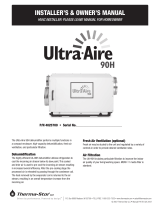
Single Run Capacitor Wiring Diagram
The graphic is a reproduction of a Fasco motor. It is basically self-explanatory.
The only thing missing from this graphic is the motor rotation wiring which is a
yellow and a purple wire that will reverse the direction of the motor depending on
what direction is needed. Some are clockwise, and some are counter-clockwise.
Off the shelf PSC motors are generally set up to be wired for any direction you
choose depending on the direction you need the motor to rotate.
Wiring an Air Conditioner Condenser Run Capacitor Compared to a Heat
Pump Condenser Run Capacitor | How to Wire a Run Capacitor to a Motor
Air conditioners and heat pumps are different in certain ways. The air conditioner
condenser will usually only run in the summer. While the heat pump condenser
will run in the summer and the winter. The condenser fan motors in both are
essentially the same except for how they are controlled. This means they will be
wired differently in the condenser. The wiring for the air conditioner condenser

fan motor will likely have the black wire (noted in the wiring diagram) go directly
to the compressor contactor. The heat pump condenser fan motor will not. The
wiring for the heat pump condenser fan motor will be slightly different. The black
wire (noted in the wiring diagram) will likely be terminated on a control board.
This control board is the defrost control board. It also controls the condenser fan
motor in a heat pump. When a heat pump goes into the defrost cycle the
condenser fan motor for the heat pump will shut down. This enhances and
quickens the defrost cycle. Make sure you follow the wiring diagram for the heat
pump to terminate the new condenser fan motor properly.
/