Page is loading ...

CONDENSING UNIT
*VXC20
IOG-4014A
07/2020
WARNING
19001 Kermier Rd. Waller, Tx 77484
www.goodmanmfg.com•www.amana-hac.com
© 2020 Goodman Manufacturing Company, L.P.
is a registered trademark of Maytag Corporaon or its related companies and is used under license. All rights
reserved.
IMPORTANT SAFETY INSTRUCTIONS
The following symbols and labels are used throughout
this manual to indicate immediate or potential safety
hazards. It is the owner’s and installer’s responsibility to
read and comply with all safety information and instructions
accompanying these symbols. Failure to heed safety
information increases the risk of personal injury, property
damage, and/or product damage.
WARNING
CAUTION
WARNING
PROP 65 WARNING
FOR CALIFORNIA CONSUMERS
Cancer and Reproducve Harm -
www.P65Warnings.ca.gov
0140M00517-A
“Proper sizing and installaon of equipment is crical to achieve opmal performance. Split system
air condioners and heat pumps must be matched with appropriate coil components to meet ENERGY
STAR criteria. Ask your contractor for details or visit www.energystar.gov.
IMPORTANT – This product has been designed and manufactured to meet ENERGY STAR criteria for
energy eciency when matched with appropriate coil components. However,
proper refrigerant charge and proper air ow are crical to achieve rated capacity and
eciency. Installaon of this product should follow the manufacturer’s refrigerant charging and air
ow instrucons. Failure to conrm proper charge and airow may reduce
energy eciency and shorten equipment life.”

2
INDEX
1
3
3
3
3
4
4
5
7
7
8
11
14
17
19
22
26
31
37
40
42

3
THE UNIT HAS ITS OWN PUMP-DOWN MODE. USE THE PUMP-DOWN
MODE WHILE VACUUMING THE UNIT. VACUUMING TOO LOW CAN
CAUSE INTERNAL ELECTRICAL ARCING, RESULTING IN A DAMAGED OR
FAILED COMPRESSOR.
CAUTION
SHIPPING INSPECTION
Always keep the unit upright; laying the unit on its side
or top may cause equipment damage. Shipping damage,
and subsequent investigation is the responsibility of
the carrier. Verify the model number, specications,
electrical characteristics, and accessories are correct
prior to installation. The distributor or manufacturer will not
accept claims from dealers for transportation damage or
installation of incorrectly shipped units.
This product is designed and manufactured to comply
with national codes. Installation in accordance with such
codes and/or prevailing local codes/regulations is the
responsibility of the installer. The manufacturer assumes
no responsibility for equipment installed in violation of any
codes or regulations. Rated performance is achieved after
20 hours of operation. Rated perforance is delivered at
the specied airow. See outdoor unit specication sheet
for split system models or product specication sheet for
packaged and light commercial models. Specication
sheets can be found at www.goodmanmfg.com for
Goodman
®
brand products or www.amana-hac.com for
Amana
®
brand products. Within the website, please select
the residential or commercial products menu and then
select the submenu for the type of product to be installed,
such as air conditioners or heat pumps, to access a list
of product pages that each contain links to that model’s
specication sheet.
The United States Environmental Protection Agency (EPA)
has issued various regulations regarding the introduction
and disposal of refrigerants. Failure to follow these
regulations may harm the environment and can lead to
the imposition of substantial nes. Should you have any
questions please contact the local oce of the EPA.
If replacing a condensing unit, heat pump or air handler,
the system must be manufacturer approved and Air
Conditioning, Heating and Refrigeration Institute (AHRI)
matched.
NOTICE
Outdoor inverter units are approved for operation above
0°F in cooling mode and -20°F (RH10%) in heating mode
with no additional kit necessary.
Damage resulting from operation of the units in a structure
that is not complete (either as port of new construction or
renovation) is not covered by our warranties.
FEATURES
This air conditioner is part of a ComfortBridge™ control
system that uses inverter technology to more eciently
control heat gain/loss with better eciency and achieve
targeted comfort conditions.
The system utilizes digital communication between the
indoor and outdoor equipment and can be controlled by
any single-stage thermostat.
The ComfortBridge control system reduces the number
of required thermostat wires, provides additional setup
features and enhanced diagnostics through Bluetooth
connectivity with the CoolCloud™ app.
Due to components using inverter technology, the air
conditioner will not function properly if used with a non-
approved control system.
NOTICE
Special consideration must be given to location of the
condensing unit(s) in regard to structures, obstructions,
other units, and any/all other factors that may interfere with
air circulation. Where possible, the top of the unit should
be completely unobstructed; however, if vertical conditions
require placement beneath an obstruction there should
be a minimum of 60 inches between the top of the unit
and the obstruction(s). The specied dimensions meet
requirements for air circulation only. Consult all appropriate
regulatory codes prior to determining nal clearances.

4
Another important consideration in selecting a location for
the unit(s) is the angle to obstructions. Either side adjacent
the valves can be placed toward the structure provided the
side away from the structure maintains minimum service
clearance. Corner installations are strongly discouraged.
AA AAA
A
CC
C
C
NOT
RECOMMENDED
AA
AA
AA
AA
AA
B B B
B
Model Type A B C AA
Residential 10" 10" 18" 20"
12" 12" 18" 24"
This unit can be located at ground oor level or on at
roofs. At ground oor level, the unit must be on a solid,
level foundation that will not shift or settle. To reduce the
possibility of sound transmission, the foundation slab
should not be in contact with or be an integral part of the
building foundation. Care should be taken to ensure the
unit is installed away from noise sensitive locations such as
bedrooms, windows and outdoor living areas. Ensure the
foundation is sucient to support the unit. A concrete slab
raised above ground level provides a suitable base.
If it is necessary to install this unit on a roof structure,
ensure the roof structure can support the weight and that
proper consideration is given to the weather-tight integrity
of the roof. Since the unit can vibrate during operation,
sound vibration transmission should be considered when
installing the unit. Vibration absorbing pads or springs can
be installed between the condensing unit legs or frame and
the roof mounting assembly to reduce noise vibration.
The unit should be well grounded so that potential
eects of electrical noise from the inverter to surrounding
equipment can be minimized.
When selecting an installation location, keep sucient
distance from the air conditioner unit and wiring to radios,
personal computers, stereos, etc., as shown in the
following gure.
Circuit
Breaker
(In.)
Radio, TV
6
0
”
o
r
m
o
re
To Indoor Unit and Thermostat
6
0
”
or
m
or
e
While these items will not cover every conceivable
situation, they should serve as a useful guide.
T
O
AVOID
POSSIBLE
INJURY
,
EXPLOSION
OR
DEATH
,
PRACTICE
SAFE
HANDLING
OF
REFRIGERANTS
.
WARNING
T
O
AVOID
POSSIBLE
EXPLOSION
,
USE
ONLY
RETURNABLE
(
NOT
DISPOSABLE
)
SERVICE
CYLINDERS
WHEN
REMOVING
REFRIGERANT
FROM
A
SYSTEM
.
• E
NSURE
THE
CYLINDER
IS
FREE
OF
DAMAGE
WHICH
COULD
LEAD
TO
A
LEAK
OR
EXPLOSION
.
• E
NSURE
THE
HYDROSTATIC
TEST
DATE
DOES
NOT
EXCEED
5
YEARS
.
• E
NSURE
THE
PRESSURE
RATING
MEETS
OR
EXCEEDS
400
PSIG
.
W
HEN
IN
DOUBT
,
DO
NOT
USE
CYLINDER
.
WARNING
REFRIGERANTS
ARE
HEAVIER
THAN
AIR
. T
HEY
CAN
“
PUSH
OUT
”
THE
OXYGEN
IN
YOUR
LUNGS
OR
IN
ANY
ENCLOSED
SPACE
. T
O
AVOID
POSSIBLE
DIFFICULTY
IN
BREATHING
OR
DEATH
:
• N
EVER
PURGE
REFRIGERANT
INTO
AN
ENCLOSED
ROOM
OR
SPACE
. B
Y
LAW
,
ALL
REFRIGERANTS
MUST
BE
RECLAIMED
.
• I
F
AN
INDOOR
LEAK
IS
SUSPECTED
,
THOROUGHLY
VENTILATE
THE
AREA
BEFORE
BEGINNING
WORK
.
• L
IQUID
REFRIGERANT
CAN
BE
VERY
COLD
. T
O
AVOID
POSSIBLE
FROSTBITE
OR
BLINDNESS
,
AVOID
CONTACT
AND
WEAR
GLOVES
AND
GOGGLES
. I
F
LIQUID
REFRIGERANT
DOES
CONTACT
YOUR
SKIN
OR
EYES
,
SEEK
MEDICAL
HELP
IMMEDIATELY
.
• A
LWAYS
FOLLOW
EPA
REGULATIONS
. N
EVER
BURN
REFRIGERANT
,
AS
P
OISONOUS
GAS
WILL
BE
PRODUCED
.
WARNING

5
T
O
AVOID
POSSIBLE
EXPLOSION
:
•N
EVER APPLY FLAME OR STEAM TO A REFRIGERANT CYLINDER. IF YOU
MUST HEAT A CYLINDER FOR FASTER CHARGING, PARTIALLY IMMERSE
IT IN WARM WATER.
•N
EVER FILL A CYLINDER MORE THAN 80% FULL OF LIQUID
REFRIGERANT.
•N
EVER ADD ANYTHING OTHER THAN R-410A TO A RETURNABLE
R-410A CYLINDER. THE SERVICE EQUIPMENT USED MUST BE LISTED
OR CERTIFIED FOR THE TYPE OF REFRIGERANT USE.
•S
TORE CYLINDERS IN A COOL, DRY PLACE. NEVER USE A CYLINDER
AS
A PLATFORM OR A ROLLER.
WARNING
THE COMPRESSOR PVE OIL FOR R-410A UNITS IS EXTREMELY
SUSCEPTIBLE TO MOISTURE ABSORPTION AND COULD CAUSE
COMPRESSOR FAILURE. DO NOT LEAVE SYSTEM OPEN TO ATMOSPHERE
ANY LONGER THAN
NECESSARY
FOR INSTALLATION.
CAUTION
Use only refrigerant grade (dehydrated and sealed) copper
tubing to connect the condensing unit with the indoor unit.
After cutting the tubing, install plugs to keep refrigerant
tubing clean and dry prior to and during installation. Tubing
should always be cut square keeping ends round and free
from burrs. Clean the tubing to prevent contamination.
The liquid line must be insulated if more than 50 ft. of liquid
line will pass through an area that may reach temperatures
of 30 °F or higher than ambient in cooling mode and/or if
the temperature inside the conditioned space may reach a
temperature lower than ambient in heating mode. Never
attach a liquid line to any uninsulated potion of the suction
line.
Do NOT let refrigerant lines come in direct contact with
plumbing, ductwork, oor joists, wall studs, oors, and
walls. When running refrigerant lines through a foundation
or wall, openings should allow for sound and vibration
absorbing material to be placed or installed between tubing
and foundation. Any gap between foundation or wall and
refrigerant lines should be lled with a pliable silicon-
based caulk, RTV or a vibration damping material. Avoid
suspending refrigerant tubing from joists and studs with
rigid wire or straps that would come in contact with the
tubing. Use an insulated or suspension type hanger. Keep
both lines separate and always insulate the suction line.
Insulation is necessary to prevent condensation from
forming and dropping from the suction line. Armex or
satisfactory equivalent with 3/8” min. wall thickness is
recommended. In severe conditions (hot, high humidity
areas) 1/2” insulation may be required. Insulation must
be installed in a manner which protects tubing and
connections from damage and contamination.
Where possible, drain as much residual compressor
oil from existing systems, lines, and traps; pay close
attention to low areas where oil may collect. NOTE:
If changing refrigerant, the indoor coil and metering
device must be replaced. Only AVPEC** air handlers or
TXV-V** expansion valves are compatible and have been
manufacturer approved for use with these models. See unit
specications or AHRI for an approved system match.
2 3/4 3/8
3 7/8 3/8
4 1 1/8 3/8
5 1 1/8 3/8
INTERCONNECTING TUBING
If burying refrigerant lines can not be avoided, use the
following checklist:
1. Insulate liquid and suction lines separately.
2. Enclose all underground portions of the refrigerant
lines in waterproof material (conduit or pipe) sealing
the ends where tubing enters/exits the enclosure.
3. If the lines must pass under or through a concrete
slab, ensure lines are adequately protected and
sealed.

6

7
IMPORTANT
1. The ends of the refrigerant lines must be cut square,
deburred, cleaned, and be round and free from nicks
or dents. Any other condition increases the chance of
a refrigerant leak.
2. Purge with nitrogen at 2 to 3 psig during brazing
to prevent the formation of copper-oxide inside
the refrigerant lines. The FVC oils used in R-410A
applications will clean any copper-oxide present
from the inside of the refrigerant lines and spread it
throughout the system. This may cause a blockage or
failure of the metering device.
3. After brazing, quench the joints with water or a wet
cloth to prevent overheating of the service valve.
4. A bi-ow lter drier is shipped with the unit as a
separate component and must be brazed on by the
installer on-site. Ensure the bi-ow lter drier paint
nish is intact after brazing. If the paint of the steel
lter drier has been burned or chipped, repaint or treat
with a rust preventative.
The recommended location of the lter drier is before the
expansion device at the indoor unit.
Do NOT make nal refrigerant line connection until plugs
are removed from refrigerant tubing.
T
O
AVOID
THE
RISK
OF
FIRE
OR
EXPLOSION
,
NEVER
USE
OXYGEN
,
HIGH
PRESSURE
AIR
OR
FLAMMABLE
GASES
FOR
LEAK
TESTING
OF
A
REFRIGERATION
SYSTEM
.
WARNING
T
O
AVOID
POSSIBLE
EXPLOSION
,
THE
LINE
FROM
THE
NITROGEN
CYLINDER
MUST
INCLUDE
A
PRESSURE
REGULATOR
AND
A
PRESSURE
RELIEF
VALVE
. T
HE
PRESSURE
RELIEF
VALVE
MUST
BE
SET
TO
OPEN
AT
NO
MORE
THAN
150
PSIG
.
WARNING
To locate leaks, pressure test the system using dry
nitrogen or leak detector uid per the manufacturer’s
recommendation. If you wish to use a leak detector,
charge the system to 10 psi using the appropriate
refrigerant then use nitrogen to nish charging the system
to working pressure then apply the detector to suspect
areas. If leaks are found, repair them. After repair, repeat
the pressure test. If no leaks exist, proceed to System
Start-up Procedure.
Adequate refrigerant charge for the matching indoor coil
and 15 feet of line set is supplied with the condensing
unit. If liquid line set exceeds 15 feet in length, refrigerant
should be added at 0.6 ounces per foot of liquid line.
V
IOLATION
OF
EPA
REGULATIONS
MAY
RESULT
IN
FINES
OR
OTHER
PENALTIES
.
NOTICE
ALL UNITS SHOULD HAVE A HIGH VOLTAGE POWER SUPPLY CONNECTED
2
HOURS
PRIOR TO STARTUP.
NOTICE
REFRIGERANT UNDER PRESSURE!
• D
O
NOT
OVERCHARGE
SYSTEM
WITH
REFRIGERANT
.
• D
O
NOT
OPERATE
UNIT
IN
A
VACUUM
OR
AT
NEGATIVE
PRESSURE
.
F
AILURE
TO
FOLLOW
PROPER
PROCEDURES
MAY
CAUSE
PROPERTY
DAMAGE
,
PERSONAL
INJURY
OR
DEATH
.
WARNING
CAUTION

8
U
SE
REFRIGERANT
CERTIFIED
TO
AHRI
STANDARDS
. U
SED
REFRIGERANT
MAY
CAUSE
COMPRESSOR
DAMAGE
,
AND
THE
WARRANTY
. M
OST
PORTABLE
MACHINES
CANNOT
CLEAN
USED
REFRIGERANT
TO
MEET
AHRI
STANDARDS
.
IS
NOT
COVERED
UNDER
CAUTION
Liquid and suction valves on condensing unit are closed to
contain the charge within the unit. The unit is shipped with
the valve stems closed and caps installed. Do not open
valves until the indoor coil and line set is evacuated.
CAUTION
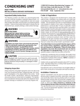
1. Connect the vacuum pump with 500 micron capability
to the service valves.
2. Evacuate the system to 500 microns or less using
gas and liquid service valves. Using both valves is
necessary.
3. Close pump valve and hold vacuum for 10 minutes.
Typically pressure will rise during this period.
• If the pressure rises to 1000 microns or less and
remains steady the system is considered leak-
free; proceed to start-up.
• If pressure rises above 1000 microns but holds
steady below 2000 microns, moisture and/or
noncondensibles may be present or the system
may have a small leak. Return to step 2: If the
same result is encountered check for leaks as
previously indicated and repair as necessary then
repeat evacuation.
• If pressure rises above 2000 microns, a leak is
present. Check for leaks as previously indicated
and repair as necessary then repeat evacuation.
5000
4500
4000
3500
3000
2500
2000
1500
1000
500
0 1 2 3 4 5 6 7 8 9
10
PRESENT
MINUTES
V
ACUUM
IN
MICRONS
NO
NO
HIGH VOLTAGE
!
D
ISCONNECT
ALL
POWER
BEFORE
SERVICING
.
M
ULTIPLE
POWER
SOURCES
MAY
BE
PRESENT
. F
AILURE
TO
DO
SO
MAY
CAUSE
PROPERTY
DAMAGE
,
PERSONAL
INJURY
OR
DEATH
DUE
TO
ELECTRIC
SHOCK
. W
IRING
MUST
CONFORM
WITH
NEC
OR
CEC
AND
ALL
LOCAL
CODES
. U
NDERSIZED
WIRES
COULD
CAUSE
POOR
EQUIPMENT
PERFORMANCE
,
EQUIPMENT
DAMAGE
OR
FIRE
.
WARNING
T
O
AVOID
THE
RISK
OF
FIRE
OR
EQUIPMENT
DAMAGE
,
USE
COPPER
CONDUCTORS
.
WARNING
GROUNDING REQUIRED!
ALWAYS INSPECT AND USE PROPER SERVICE TOOLS. LACK OF
INSPECTION OR IMPROPER TOOLS MAY CAUSE EQUIPMENT DAMAGE OR
PERSONAL INJURY. ALL DISCONNECTED GROUNDING DEVICES MUST BE
RECONNECTED BEFORE INSTALLING OR SERVICING. MULTIPLE
COMPONENTS OF THIS UNIT MAY CONDUCT ELECTRICAL CURRENT;
THESE ARE GROUNDED. IF SERVICING THE UNIT, ANY DISCONNECTION
OF GROUNDING WIRES, SCREWS, STRAPS, CLIPS, NUTS OR WASHERS
USED TO COMPLETE THE GROUND MUST BE RETURNED TO THEIR
ORIGINAL POSITION AND PROPERLY FASTENED.
CAUTION
NOTICE
•
•
•
The condensing unit rating plate lists pertinent electrical
data necessary for proper electrical service and
overcurrent protection. Wires should be sized to limit
voltage drop to 2% (max.) from the main breaker or fuse
panel to the condensing unit. Consult the NEC, CEC, and
all local codes to determine the correct wire gauge and
length.

9
Local codes often require a disconnect switch located near
the unit; do not install the switch on the unit.
The inverter control system software provides sucient
time delay to protect from overcurrent conditions and
permit the compressor and fan motors to adjust their
rotational speed.
Route power supply and ground wires through the high
voltage port and terminate in accordance with the wiring
diagram provided inside the control panel cover.
• Make sure to apply the rated voltage of 208/230V for
the unit.
• Use conduit for power supply cables.
• A power circuit (see the production specication
sheet or the unit serial plate) must be provided for
connection of the unit. This circuit must be protected
with the required safety devices.
• When using residual current operated circuit breakers,
be sure to use a high-speed type (0.1 seconds or
less) 200 mA rated residual operating current.
• Use copper conductors only.
• Use insulated wire for the power cord.
• Select the power supply cable type and size
in accordance with relevant local and national
regulations.
• Outside the unit, make sure to keep the wirings 5 inch
away. Otherwise, the outdoor unit may be aected by
electrical noise (external noise), and malfunction or
fail.
• Make sure the wirings will not be pinched by the front
panel, and close the panel rmly.
• Route the conduit along the unit and so on to prevent
wirings from being stepped on.
The unit is designed to work as part of a fully
communicating HVAC system, utilizing either:
• ComfortBridge compatible indoor unit with any 24V
single stage thermostat.
• CTK04AE or newer thermostat (If paired with
ComfortNet compatible indoor unit.)
Route control wires through the low voltage port and
terminate in accordance with the wiring diagram provided
inside the control panel cover.
ComfortBridge
™
control system low voltage wiring consists
of two wires between the indoor unit and outdoor unit. The
required wires are data lines 1 and 2.
The thermostat needs 4 wires between the indoor unit and
thermostat or 5 wires if the thermostat requires a Common
wire.
Regarding the wiring of the indoor unit to the thermostat,
also refer to ComfortBridge compatible indoor unit’s Install
manual (in case of communicating inverter system.).
If installing with a CTK04 thermostat, please see the
addendum for further instructions.

10
The condenser unit is shipped with a predetermined factory
charge level as shown below. For longer line sets greater
than 15 feet, add 0.6 ounces of refrigerant per foot. Refer
to the following page for the equivalent length of the elbow
ttings.
NOTICE
T
OTAL
R
EFRIGERANT
=
F
ACTORY
C
HARGE
+ (0.6
OZ
./
FT
. * A
DDITIONAL
F
EET
OF
A
CTUAL
L
INE
S
ET
).
The following table shows refrigerant amounts for every 5
feet of line.
15 (Factory Charge) 152 154 246 246
20 155 157 249 249
25 158 160 252 252
30 161 163 255 255
35 164 166 258 258
40 167 169 261 261
45 170 172 264 264
50 173 175 267 267
55 176 178 270 270
60 179 181 273 273
65 182 184 276 276
70 185 187 279 279
75 188 190 282 282
80 191 193 285 285
85 194 196 288 288
90 197 199 291 291
95 200 202 294 294
100 203 205 297 297
105 206 208 300 300
110 209 211 303 303
115 212 214 306 306
120 215 217 309 309
125 218 220 312 312
130 221 223 315 315
135 224 226 318 318
140 227 229 321 321
145 230 232 324 324
150 233 235 327 327
155 236 238 330 330
160 239 241 333 333
165 242 244 336 336
170 245 247 339 339
175 248 250 342 342
180 251 253 345 345
185 254 256 348 348
190 257 259 351 351
195 260 262 354 354
200 263 265 357 357
CAUTION
OPEN THE LIQUID VALVE FIRST! IF THE SUCTION SERVICE VALVE IS OPENED
FIRST, OIL FROM THE COMPRESSOR MAY BE DRAWN INTO THE INDOOR
COIL TXV RESTRICTING
REFRIGERANT FLOW AND AFFECTING OPERATION OF THE SYSTEM.

11
POSSIBLE REFRIGERANT LEAK!
T
O AVOID A POSSIBLE REFRIGERANT LEAK, OPEN THE SERVICE VALVES
UNTIL THE TOP OF THE STEM IS 1/8” FROM THE RETAINER.
CAUTION
ENSURE VALVES ARE OPEN AND ADDITIONAL CHARGE IS ADDED PER
CHART BEFORE APPLYING POWER.
CAUTION
When opening valves with retainers, open each valve
only until the top of the stem is 1/8” from the retainer. To
avoid loss of refrigerant, DO NOT apply pressure to the
retainer. When opening valves without a retainer, remove
service valve cap and insert a hex wrench into the valve
stem and back out the stem by turning the hex wrench
counterclockwise. Open the valve until it contacts the rolled
lip of the valve body.
After the refrigerant charge has bled into the system,
open the liquid service valve. The service valve cap is
the secondary seal for the valves and must be properly
tightened to prevent leaks. Make sure cap is clean and
apply refrigerant oil to threads and sealing surface on
inside of cap. Tighten cap nger-tight and then tighten
additional 1/6 of a turn to properly seat the sealing
surfaces.
Do not introduce liquid refrigerant from the cylinder into the
crankcase of the compressor (suction side) as this may
damage the compressor.
Break vacuum by fully opening liquid and gas base valve.
NOTICE
A system verication test is now required to check the
equipment settings and functionality.
Inverter units are tested by any of the following methods:
• Setting the “SUt” menu (System verication test)
to ON through the indoor unit control board push
buttons.
• Setting the System verication test menu of mode
display screen-4 to ON through the outdoor unit
control board push buttons.
• Through the CoolCloud HVAC phone application
Once selected, it checks the equipment for approximately 5
- 15 minutes. System test may exceed 15 minutes if there
is an error. Refer to the Troubleshooting section.
NOTICE
The CoolCloud HVAC phone application was designed
to improve the contractor’s setup /diagnostic experience.
This application can only be used with ComfortBridge
compatible indoor units and can be downloaded through
the Google Play or Apple App Store.
Users can see specic model information, review active
diagnostic error codes, observe system status during
operation, make system menu adjustments, add site visit
notes and run system testing of all operational modes (heat
/ cool / fan) directly from the phone.
If installing with a CTK04 thermostat, please see the
addendum for further instructions.

12
CHARGE MODE allows for charging of the system.
System operates for a duration of approximately one hour
while the equipment runs at full capacity.
After one hour, the CHARGE MODE ends and the system
resumes normal operation.
Before starting the CHARGE MODE, turn o the Cool or
Heat mode and electric heater or gas furnace.
a. Inverter units are charged by any of the following
methods:
• setting the “CR9” menu (Charge Mode) to ON through
the indoor unit control board push buttons.
• setting the Charge mode menu of mode display
screen-4 to ON through the outdoor unit control board
push buttons.
• Through the CoolCloud HVAC phone application.
b. The System will remain in charge mode (high speed)
for 60 minutes before timing out.
c. When charge mode is complete, the installer must
manually shut o.
If installing with a CTK04 thermostat, please see the
addendum for further instructions.
Using service equipment, add or recover refrigerant
according to the calculation in Step 1. Allow system to
stabilize for 10 minutes after adjusting charge level.
1. Purge gauge lines.
2. Connect service gauge manifold to base valve service
ports.
3. Convert the liquid pressure to temperature using a
temperature/pressure chart.
4. Temporarily install a thermometer on the liquid line at
the liquid line service valve.
a. Ensure the thermometer makes adequate contact
and is insulated for best possible readings.
5. Subtract the liquid line temperature from the
converted liquid pressure to determine subcooling.
6. Before starting the Subcooling adjustment, make sure
the outdoor ambient temperature is in a below range
and the unit is operating at 100% capacity.
7. For EEV Indoor Unit: If the system subcooling is not
within the ranges shown in the following table, adjust
subcooling according to the following procedure:
a. If subcooling is low, add charge to adjust the
subcooling as specied in the following table.
b. If subcooling is high, remove chargee to lower the
subcooling to 8° ± 1°F.
< 65°F 65°F to 105°F > 105°F
Weigh in
Charge
8°F ± 1°F
Weigh in
Charge
8. For TXV Indoor Unit
The system subcooling should be 8°F ± 1°F. If not
in that range, adjust subcooling and superheat
according to the following procedure.
a. If subcooling and superheat are low, adjust TXV
to 8°F ± 1°F superheat, then check subcooling.
b. If subcooling is low and superheat is 8°F ± 1°F,
add charge to rise subcooling to 8°F ± 1°F, then
check superheat.
c. If subcooling is low and superheat is high, add
charge to rise subcooling to 8°F ± 1°F, then check
superheat.
d. If subcooling is 8°F ± 1°F and superheat is high,
adjust the TXV valve to 8°F ± 1°F superheat, then
check subcooling.
e. If subcooling and superheat are high, adjust the
TXV valve to 8°F ± 1°F superheat, then check
subcooling.
f. If subcooling is high and superheat is 8°F ± 1°F,
remove charge to lower the subcooling to 8°F ±
1°F, then check superheat.
g. If subcooling is high and superheat is low, adjust
the TXV valve to 8°F ± 1°F superheat and remove
charge to low the subcooling to 8°F ± 1°F.
h. If subcooling is 8°F ± 1°F and superheat is low,
adjust the TXV valve to 8°F ± 1°F superheat and
remove charge to lower the subcooling 8°F ± 1°F,
then check the superheat.
C
HECK
THE
S
CHRADER
PORTS
FOR
LEAKS
AND
TIGHTEN
VALVE
CORES
,
IF
NECESSARY
. I
NSTALL
CAPS
FINGER
-
TIGHT
.
NOTICE

13
D
O
NOT
ADJUST
THE
CHARGE
BASED
ON
SUCTION
PRESSURE
UNLESS
THERE
IS
A
GROSS
UNDERCHARGE
.
NOTICE
SUCTION PRESSURE
PSIG
SUCTION PRESSURE
PSIG
50 1 200 70
52 3 210 73
54 4 220 76
56 6 225 78
58
7 235 80
60 8 245 83
62
10 255
85
64 11 265 88
66 13 275 90
68 14 285 92
70 15 295 95
72 16 305 97
74 17 325 101
76 19 355 108
78 20 375 112
80 21 405 118
85 24 415 119
90 26 425 121
95 29 435 123
100 31 445 125
110 36 475 130
120 41 500 134
130 45 525 138
140 49 550 142
150 53 575 145
160 56 600 149
170 60 625 152
SATURATED SUCTION PRESSURE
TEMPERATURE CHART
SATURATED SUCTION PRESSURE
TEMPERATURE CHART
•
•
•
•
•
1 ON CT Communication Terminal Resister
2 ON CT Communication Terminal Resister
1 ON Cooling Emergency Mode*
2 ON Cooling Emergency Mode*
DS1
DS2
* DS2 sw itch 1 and 2 both must be turned on during normal operation mode
BOOST MODE can be enabled or disabled through the
control board push buttons or through the CoolCloud app.
BOOST MODE allows the system to operate at increased
compressor speed to satisfy unusually high loads. BOOST
MODE is initiated by an outdoor temperature sensor
located in the outdoor unit.
Please note that outdoor equipment operational sound
levels may increase while the equipment is running in
BOOST MODE. Disabling BOOST MODE will provide the
quietest and most ecient operation.
BOOST MODE is ON by default and is activated when the
outdoor temperature reaches 105°F. BOOST MODE can
be disabled and enabled and the activation temperature
adjusted in the Settings menu of the CoolCloud app or
through the indoor / outdoor push button menus.
If installing with a CTK04 thermostat, please see the
addendum for further instructions.

14
Dehumidication requires a thermostat capable of reading
the indoor humidity level and allowing the user to set a
dehumidication target.
The thermostat controls the humidity level of
the conditioned space using the cooling system.
Dehumidication is engaged whenever a cooling demand
is present and humidity levels are above the target level.
When this condition exists, the circulating fan output is
reduced, increasing system run time, over cooling the
evaporator coil and ultimately removing more humidity from
the structure than if only in cooling mode.
The thermostat may also allow for an additional
overcooling limit setting depending on the thermostat
utilized. This allows the cooling system to further reduce
humidity by lowering the temperature below the cooling
setpoint in an attempt to better achieve desired humidity
levels.
For eective dehumidication operation:
• Ensure “Dehumidication selection” is NOT set to
“OFF”.
• Verify the cooling airow prole is set to “Prole D”.
- See the Cool Set-up section of the Installation Manual for
complete airow prole details.
- By default, “Dehumidication selection” is standard and
the cooling airow prole is set to “Prole D”.
• For additional dehumidication control, airow settings
are eld adjustable and can be ne-tuned to a value
that is comfortable for the application from a range of
Cool Airow Trim.
• In addition, the system can have Enhanced
Dehumidication operation in setting “A”, “B”,
or “C” of “Dehumidication Selection” based on
dehumidication demand.
- See the DEHUMIDIFICATION SELECT section of the
Installation Manual for more detail.
The ComfortBridge based inverter heating and air
conditioning system uses an indoor unit and outdoor unit
digitally communicating with one another via a two-way
communications path. ComfortBridge is compatible with
any 24 VAC single stage thermostat which sends inputs to
the indoor unit.
The ComfortBridge system permits access to system
information, advanced set-up features, and advanced
diagnostic/troubleshooting features via the control board
push buttons or the CoolCloud HVAC app.
(If using a CTK04 thermostat, please see the addendum
for further instructions.)
The air conditioner’s diagnostics menu provides access
to the most recent faults. The six most recent faults can
be accessed through the control board seven segment
displays or the CoolCloud mobile app. Any consecutively
repeated fault is stored a maximum of three times.
Example: A leak in the system, low refrigerant charge or an
incompletely open stop valve can cause the unit to ash
error code E15. This error code suggests that the unit is
experiencing operation at low pressure. The control will
only store this fault the rst three consecutive times the
fault occurs.
This menu displays information about the systems current
status. This menu can be utilized to conrm correct
functionality of the equipment and for troubleshooting
purposes.
The following items will be displayed:
• Heat Capacity Request Percentage
• Cool Capacity Request Percentage
• Heat Capacity Request During Defrost Percentage
• Dehumidication Request Percentage
• Reversing Valve Status
• Reported Airow by Indoor Unit
• Boost Mode
• Previous Defrost Run Time
* Information specic to the heat pump is not
displayed.

15
The following sensor values will be displayed:
• Outdoor Temperature
• Coil Temperature
• Liquid Line Temperature
• Discharge Temperature
• Defrost Sensor
• Suction Pressure
This function can be enabled in this menu.
* Information specic to the heat pump is not displayed.
The system allows for the adjustment of several cooling
performance variables. Cool Airow Trim (*1), Cool Airow
Proles, Cool Fan ON Delay, Cool Fan OFF Delay and
Dehumidication Select (some enable option or o) can
be adjusted in this menu. You can also reset this entire
menu to factory default settings. See the following images
showing the four cooling airow proles.
• provides only an OFF delay of one (1)
minute at 100% of the cooling demand airow.
• ramps up to full cooling demand airow
by rst stepping up to 50% of the full demand for
30 seconds. The motor then ramps to 100% of the
required airow. A one (1) minute OFF delay at 100%
of the cooling airow.
50% CFM
1/2 min
100% CFM
100% CFM
1 min
OFF
OFF
• ramps up to 82% of the full cooling demand
airow and operates there for approximately 7 1/2
minutes. The motor then steps up to the full demand
airow. Prole C also has a one (1) minute 100% OFF
delay.
100% CFM
OFF
OFF
• (default) ramps up to 50% of the demand
for 1/2 minute, then ramps to 82% of the full cooling
demand airow and operates there for approximately
7 1/2 minutes. The motor then steps up to the full
demand airow. Prole D has a 1/2 minute at 50%
airow OFF delay.
OFF
OFF
*1
1. At Cool and Heat Hi speed trim, *VXC200601* with
**VC960804C, **VM970804C and *MVC800804C
combination trim more than 5% settings are invalid.
Trimmed up CFM makes miss matching error.
2. At Cool Hi speed trim, Other than the above,
depending on the connected indoor unit, there are
restrictions on the positive side Trim setting.
If you want to change the Cool Airow Trim to positive
side, be sure to conrm the Airow Trim restrictions
in the latest indoor unit installation manual. The
latest manual can be obtained from the website
“PartnerLink(InfoFinderPlus/Literature)”.
[PartnerLink URL]
https://partnerlinkmarketing.goodmanmfg.com/
goodman/info-nder-plus
3. The Inverter system uses lower compressor speed
and lower indoor unit CFM to optimize system
performance. To obtain 100% CFM for home
circulation, use full Trim setting instead of Int/
Low speed. This is recommended for applications
with unusually cold return temperatures such as
basements.
When Dehumidication mode exists, the circulating fan
output is reduced, increasing system run time, over cooling
the evaporator coil and ultimately removing more humidity
from the structure than if only in cooling mode.
The system can have Dehumidication operation in setting
“Standard”, “A”, “B” or “C” of “dehumidify with cooling”
menu based on dehumidication demand.
Setting “Standard” allows for the widest compressor
operation range with lower CFM than Cooling mode.
In the Enhanced Dehumidication (setting A, B and C)
the indoor airow is lower than Standard Dehumidication
(Standard).
Setting “A” allows for the same compressor operation
range as standard Dehumidication with lower CFM than
standard dehumidication (Standard).
Setting “B” limits compressor operation range and keeps
high dehumidication capacity.

16
In setting “C” the system runs xed at 100% compressor
and airow. See Figure 1.
Max compressor speed at which the outdoor unit will
operate can be changed through the control board seven
segment displays or the CoolCloud mobile app.
Max compressor speed can be changed to get the required
capacity or eciency.
Once the maximum speed is set, the system operates
between the set maximum speed and default low speed.
When determining the appropriate compressor speed
for cooling and heating, in the “RPS Range For Cooling/
Heating” menu select the range that contains the desired
value.
(Then, after pressing the Apply Changes button, leave the
Device setting menu and enter the this menu again.
Otherwise, the changed settings will not be reected.)
Next, in the “Selected RPS for Cooling/Heating” menu,
select the desired RPS within the displayed range.

17
A representative menu is posted. Item names and setting value are subject to change.
SUBMENU ITEM INDICATION/USER MODIFIABLE OPTIONS COMMENTS
ALL (The Active and History Fault codes are displayed.) Active fault code and up to 6 fault code histories.
ACTIVE (The Active Fault codes are displayed.) Active fault code only.
HISTORY (The History Fault codes are displayed .) Up to 6 fault code histories.
REFRESH N/A Selecting this menu will refresh the display.
SUBMENU ITEM INDICATION/USER MODIFIABLE OPTIONS COMMENTS
HVAC DEVICE AIR CONDITIONER(AC)
The type of HVAC Device.
FIRMWARE VERSION **
Specific number associated with the control
software.
MODEL NUMBER *VXC200*01*
This number match the model name found on the
serial plate.
SERIAL NUMBER *********
This number match the serial number found on the
serial plate.
SUBMENU ITEM INDICATION(Units) COMMENTS
COOL CAPACITY REQUEST %
The request for cooling.
0% means the system is off.
All other values mean the system is running.
DEHUMIDIFICATION REQ UEST %
Request for dehumidification.
0% means dehumidification is not being requested.
All other values mean dehumidification is being
requested.
OUTDOOR FAN SPEED RPM
Current speed of the outdoor fan in rotations per
minute.
REQUESTED AIRFLOW CFM
This is the airflow the indoor unit will try to deliver
while the unit is active.
REPORTED AIRFLOW CFM
Indoor airflow (in cubic feet per minute) as reported
by the indoor unit.
BOOST MODE OFF or ON
If this feature is available and enabled, an inverter
can ramp the compressor above default speeds to
increase capacity.
This shows if the feature is active or inactive.
To check if this function is enabled, find the Boost
Mode Enable item in the setting for this unit.
SUBMENU ITEM INDICATION(Units) COMMENTS
OUTDOOR TEMP F Displays the outdoor air temperature.
LIQUID LINE TEMP F Displays the outdoor liquid temperature.
DISCHARGE TEMP F Displays the outdoor discharge temperature.
SUCTION PRESSURE PSI
Displays the pressure of taken slightly upstream of
the suction accumulator.

18
A representative menu is posted. Item names and setting value are subject to change.
*1 At Cool and Heat Hi speed trim, *VXC200601* with **VC960804C, **VM970804C and *MVC800804C combination trim more than 5% settings are
invalid. Trimmed up CFM makes miss matching error.
*2 Other than the above, depending on the connected indoor unit, there are restrictions on the positive side Trim setting.
If you want to change the Cool Airow Trim to positive side, be sure to conrm the Airow Trim restrictions in the latest indoor unit installation manual.
The latest manual can be obtained from the website “PartnerLink(InfoFinderPlus/Literature)”.
[PartnerLink URL]
https://partnerlinkmarketing.goodmanmfg.com/goodman/info-nder-plus
*3 The Inverter system uses lower compressor speed and lower indoor unit CFM to optimize system performance.
To obtain 100% CFM for home circulation, use full Trim setting instead of Int/Low speed.
This is recommended for applications with unusually cold return temperatures such as basements.
*4 Please refer to the page of “DEHUMIDIFICATION SELECT “ for details of this function.
SUBMENU ITEM INDICATION(Units) COMMENTS
BOOST MODE ENABLE OFF or ON
BOOST MODE is ON by default. See BOOST MODE
section of this manual for more details.
BOOST TEMP Always Active or 70F to 105F in icrements
If enabled, when the ambient outdoor temperature is
greater than this selected value, boost mode will be
operational.
Below this temperature the mode will not function.
There is also an option to keep boost mode
countinuousl
y
enabled
INDOOR/OUTDOOR HEIGHT DIFFERENCE
Both Units at Same Level,
Outdoor Unit is Lower, or
Indoor Unit is Lower
If the outdoor & indoor units are within +/- 15 ft. vertical
distance, select SAME LEVEL. If the outdoor unit is
more than 15 ft. below the indoor unit, select OUTDOOR
LOWER. If the outdoor unit is more than 15 ft. above the
indoor unit, select INDOOR LOWER.
RESET FOR SYSTEM SETUP NO or YES
Selecting yes will reset any system setting to their factor
y
defaults.
SYSTEM VERIFICATION TEST OFF or ON
System Verification Test must be run after installation.
This is approximately a 5-15 minute test. If operation
mode is set to COOL mode, the system will enter
CHARGE mode upon completion, otherwise it will stop.
PUMP DOWN OFF or ON
Enter PUMP DOWN Mode.
This procedure runs the equipment for approximately 15
minutes and allows accumulation of refrigerant at
the outdoor unit for purposes of removing & replacing th
e
indoor unit or outdoor unit.
ACTIVATE CHARGE MODE OFF or ON
Enter Charging Mode. This allows for a steady system
operation for a duration of approximately 1 hour to allow
for refrigerant charging of the system via the charge port.
COOLING TRIM FACTOR(HIGH)
*1, 2
-15% to +15% in 5% increments
Select this airflow trim when inverter system is running
high compressor speeds during a cooling cycle.
COOLING TRIM FACTOR(MID)
-15% to +15% in 5% increments,20 30, Full(Max)
*3
Select this airflow trim when inverter system is running
mid-range (intermediate) compressor speeds during a
cooling cycle.
COOLING TRIM FACTOR(LOW)
-15% to +15% in 5% increments,20 30, Full(Max)
*3
Select this airflow trim when inverter system is running
low compressor speeds during a cooling cycle.
COOLING AIRFLOW PROFILE A, B, C, or D
If it is desirable to quickly ramp up the indoor airflow
select profile A.
If it is desirable to reach nominal airflow quickly, but a
slower ramp up time is required, select profile B.
If dehumidification is required immediately when cooling
mode begins select profile C.
If a slower airflow ramp up / ramp down time is required
in addition to dehumidification select profile D.
BLOWER ON DELAY-COOLING 5, 10, 20 or 30 Seconds
Delay between compressor turning on and indoor blower
turning on during a cooling cycle.
BLOWER OFF DELAY-COOLING 30, 60, 90 or 120 Seconds
Delay between compressor shutting off and the indoor
blower shutting off after a cooling cycle.
DEHUMIDIFICATION ENABLE
*4
Standard, OFF, A, B or C
Selecting "OFF" disables dehumidification selecting.
"Standard", "A", "B" or "C" enables dehumidification.
RESET COOLING SETTINGS NO or YES
Selecting yes will reset any cooling setting to their factor
y
defaults.
RPS RANGE FOR COOLING **.* to **.* RPS,…(Total 5 Ranges)
When determining the appropriate compressor speed for
cooling, select the range that contains the desired value.
The Selected RPS for Cooling menu is where you will
select your desired value within this selected range.
SELECTED RPS FOR COOLING **.* RPS
This value will be a number inside the RPS Range for
Cooling.
If you'd like to select a RPS from a different range, you
must change the RPS Range for Cooling setting first,
then restart the device setting page
RESET FAULT HISTORY NO or YES Selecting yes will clear the fault histories of device.
AIR CONDITIONER(AC) / DEVICE SETTING

19
Wiring is subject to change. Always refer to the wiring diagram on the unit for the most up-to-date wiring.
*VXC200241**; *VXC200361**
1.THE POSITION OF THE SELECTOR SWITCHES (DS1/DS2) INDICATE FACRTORY SETTING.
2. MOTOR OVERLOAD PROTECTION PROVIDED BY INVERTER: SEE TABLE
3. USE COPPER CONDUCTORS ONLY.
4. CLASS 2 WIRE
NOTES:
0
X11A
AMBIENT
SEG
1
SEG
2
SEG
3
U
V
W
BK
RD
YL
BK
WH
RD
L2
L1
TERMINAL BLOCK
FIELD WIRING
H/LPT
COMPRESSOR
TERMINAL ORIENTATION
X108A
Z1C
Z2C
1
2
R
C
W1
Y1
Y2
L
TO INDOOR
UNIT
X17A
+
-
HPS
E1
HR1
HR3
BR
WH
HR2
HR4
X32A
X851A
POWER CONDITIONER
X12A
L
I
Q
U
ID
L
I
N
E
D
IS
C
H
A
R
G
E
L
I
N
E
GR
RD
Z3C
RD
BK
PU
GROUND LUG
V
W
U
NOTE 1
1
OFF
ON
SEE NOTE 3
SEE NOTE 3
2
X52A
SHARE DATA
Z4C
BS1
BS2
BS3
C
O
I
L
C
IR
C
U
I
T
RD
YL
GR
M1C
M1F
+
-
THERMISTOR/TEMPRATURE SENSOR
MOTOR
HIGH/LOW PRESSURE TRANSDUCER(H/LPT)
HIGH PRESSURE SWITCH(HPS)
DS1/DS2 DIP SWITCH
SEG1-SEG3 7-SEGEMENT DISPLAY
Z1C-Z4C FERRITE CORE
BS1-BS3 PUSH BUTTON SWITCH
M1C COMPRESSOR MOTOR
M1F FAN MOTOR
TERMINAL
CONNECTOR
NOISLESS EARTH
ELECTRICAL GROUND
HIGH VOLTAGE
LOW VOLTAGE
HIGH VOLTAGE FIELD
C
O
MPONE
N
T CODE
NOTE 1
1
OFF
ON
DS1
2
INVERTER BOARD
GY
BK
RING
COLOR
TABLE
0140R00352-F
DS2
208-230 V
60 HZ
SEE NOTE 4
COLOR CODE:
RD-----------------
BR-----------------
GR-----------------
BK-----------------
WH---------------
YL-----------------
BL-----------------
PU----------------
GY-----------------
RED
BROWN
GREEN
BLACK
WHITE
YELLOW
BLUE
PURPLE
GRAY
SEE NOTE 3
PCB P/N
AC MODELS
3P357336-4 (2T)
AVXC200241
DX20VC0241
GVXC200241
3P357336-5 (3T)
AVXC200361
DX20VC0361
GVXC200361
ON
ON
OFF

20
Wiring is subject to change. Always refer to the wiring diagram on the unit for the most up-to-date wiring.
*VXC200481**
1. THE POSITION OF THE SELECTOR SWITCHES (DS1/DS2) INDICATE FACTORY SETTING.
2. MOTOR OVERLOAD PROTECTION PROVIDED BY INVERTER: SEE TABLE
3. USE COPPER CONDUCTERS ONLY.
4. CLASS 2 WIRE
NOTES:
1
2
R
C
W1
Y1
Y2
L
0
TO INDOOR
UNIT
X11A
AMBIENT
SEG
1
SEG
2
SEG
3
X17A
X851A
X99A
HPS
RD
RD
BL
M1C
BK
RD
YL
M1F
BK
WH
RD
RD
L2B
L1B
BK
NOISE FILTER
BOARD
L2A
L1A
BK
RD
L1C
L2C
TERMINAL BLOCK
FIELD
WIRING
H/LPT
GND
INVERTER BOARD
COMPRESSOR
TERMINAL ORIENTATION
X32A
X108A
GR
+
-
Z1C
Z2C
Z3C
X12A
COIL INLET
LIQUID LINE
DISCHARGE LINE
U
V
W
1
OFF
ON
DS2
2
NOTE 1
BS1
BS2
BS3
X111A
FIN THERMISTOR
X52A
SHARE DATA
NOTE 1
1
OFF
ON
DS1
2
X98A
RING
COLOR
RD
YL
GY
BK
+
-
THERMISTOR/TEMPRATURE SENSOR
MOTOR
HIGH/LOW PRESSURE TRANSDUCER(H/LPT)
HIGH PRESSURE SWITCH(HPS)
DS1/DS2 DIP SWITCH
SEG1-SEG3 7-SEGEMENT DISPLAY
Z1C-Z3C FERRITE CORE
BS1-BS3 PUSH BUTTON SWITCH
M1C COMPRESSOR MOTOR
M1F FAN MOTOR
TERMINAL
CONNECTOR
NOISLESS EARTH
ELECTRICAL GROUND
HIGH VOLTAGE
LOW VOLTAGE
HIGH VOLTAGE FIELD
C
OMPONENT CODE
NOTE 3
SEE NOTE 3
W
U
V
TABLE
0140R00353-F
GR
GR
E1
208-230 V
60 HZ
SEE NOTE 4
COLOR CODE:
RD-----------------
BR-----------------
GR-----------------
BK-----------------
WH---------------
YL-----------------
BL-----------------
RED
BROWN
GREEN
BLACK
WHITE
YELLOW
BLUE
SEE NOTE 3
PCB P/N AC MODELS
3P357343-4 (4T) AVXC200481 DX20VC0481 GVXC200481
ON
ON
OFF
/