
Document 26/737; Edition EN24 │ 2014-07-30
Manual
PCD1/ PCD2 Series

Saia-Burgess Controls AG
Manual PCD 1 / PCD 2 Series │ Document 26 / 737 EN24 │ 2014-07-30
Content
0-1
0
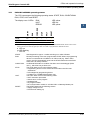
0 Contents
0.2 Brands and trademarks .................................................................................. 0-7
1 Graphical index
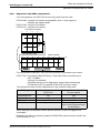
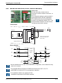
1.1 PCD1.M110/M120/M130/M125/M135 ............................................................ 1-1
1.2 PCD2.M110/M120/M150 ................................................................................. 1-2
1.3 PCD2.M170 .................................................................................................... 1-3
1.4 PCD2.M480 .................................................................................................... 1-4
2 Guidance
2.1 Introduction ..................................................................................................... 2-1
2.2 Planning an application with PCD1/2/3 components ...................................... 2-2
2.3 Cabling ............................................................................................................ 2-4
2.3.1 Cable routing .............................................................................................. 2-4
3 Saia PCD
®
Classic CPUs and expansion housings
3.1 System overview ............................................................................................. 3-1
3.1.1 Outphased Saia PCD
®
s .............................................................................. 3-1
3.1.2 Saia PCD
®
Web-Server .............................................................................. 3-1
3.2 General technical details ................................................................................. 3-2
3.3 System resources ........................................................................................... 3-4
3.3.1 Program blocks .......................................................................................... 3-4
3.3.2 Computation ranges for count types .......................................................... 3-4
3.3.3 Media .......................................................................................................... 3-5
3.3.4 Program structure for the Saia PCD
®
Classic family .................................. 3-6
3.4 CPU overview ................................................................................................. 3-7
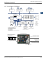
3.4.1 PCD1.M1xx ................................................................................................ 3-7
3.4.2 Block diagram : PCD1.M1xx ...................................................................... 3-8
3.4.3 HardwareandrmwareversionsforthePCD1 .......................................... 3-9
3.4.4 Firmware Upgrade for the PCD1.M110, PCD1.M120 and PCD1.M130 ..... 3-10
3.4.5 Firmware Upgrade for the PCD1.M125 and PCD1.M135 .......................... 3-10
3.4.6 PCD2.M1x0/M480 Hardware and Firmware .............................................. 3-11
3.4.7 Block diagram : PCD2.Mxx0 ...................................................................... 3-14
3.4.8 HardwareandrmwareversionsforthePCD2.M110/M120 ...................... 3-16
3.4.9 HardwareandrmwareversionsforthePCD2.M150,
FW < V0D0 (until early 2007) .................................................................... 3-16
3.4.10 HardwareandrmwareversionsforthePCD2.M150,
FW≥V0D0(sinceearly2007) .................................................................. 3-17
3.4.10 HardwareandrmwareversionsforthePCD2.M170/M480 ...................... 3-17
3.5 Mounting ......................................................................................................... 3-18
3.5.1 Mounting position and ambient temperature .............................................. 3-18
3.6 Expansion housings and bus cables ............................................................... 3-19
3.6.1 Expansion with PCD2 components ............................................................ 3-20
3.6.2 Expansion with PCD3 components ............................................................ 3-22
3.6.3 Expansion with PCD4 components ............................................................ 3-23
0 Contents

Saia-Burgess Controls AG
Manual PCD 1 / PCD 2 Series │ Document 26 / 737 EN24 │ 2014-07-30
Content
0-2
0
3.7 Installation and addressing of PCD2 I/O modules .......................................... 3-24
3.7.1 Insertion of I/O modules ............................................................................. 3-24
3.7.2 Address and terminal designation .............................................................. 3-24
3.7.3 Cable layout ............................................................................................... 3-25
3.8 Dimensions ..................................................................................................... 3-26
3.9 Power supply and connection plan ................................................................. 3-27
3.9.1 External power supply ................................................................................ 3-27
3.9.2 Earthing and connection plan ..................................................................... 3-28
3.9.3 Internal power supply ................................................................................. 3-30
3.9.4 Capacity of internal power supply .............................................................. 3-30
3.10 PCD1.M1x0 and PCD1.M1x5 operating states ............................................... 3-31
3.11 PCD2.M1x0/M480 operating states ................................................................ 3-32
3.12 PinCongurationPCD1 .................................................................................. 3-33
3.13 PinCongurationPCD2 .................................................................................. 3-34
3.14 Expansion of user memory ............................................................................. 3-35
3.14.1 Basics ......................................................................................................... 3-35
3.14.2 Memory location of the user program, the resources, texts and DBs ............. 3-35
3.14.3 Exampleofamemoryconguration ........................................................... 3-35
3.14.4 PCD1.M1x0 ................................................................................................ 3-38
3.14.5 PCD1.M125 and PCD1.M135 .................................................................... 3-40
3.14.6 PCD2.M110/M120/M150 ............................................................................ 3-42
3.15 Partitioning options for user memory ............................................................. 3-45
3.16 Data storage in case of power outage ............................................................ 3-46
3.17 Backupoftheuserprogram(ashcardforPCD2.M170/M480) ..................... 3-47
3.17.1 General ....................................................................................................... 3-47
3.17.2 Copyingtheapplicationtotheashcard(backup) .................................... 3-48
3.17.4 Backup/restore of RAM texts/DBs at run-time ............................................ 3-50
3.18 Hardware clock (Real Time Clock) .................................................................. 3-55
3.18.1 Clock module PCD2.F500 (obsolete, PCD2.M110/M120 only) .................. 3-55
3.19 Monitoring the CPU (watchdog) ...................................................................... 3-56
3.19.1 PCD1 hardware watchdog ......................................................................... 3-56
3.19.2 PCD2 hardware watchdog ......................................................................... 3-57
3.19.3 Software watchdog for PCD1 and PCD2 ................................................... 3-59
3.20 Internal LED displays and small terminals ...................................................... 3-60
3.20.1 Outphased displays and small terminals ................................................... 3-60
3.20.2 PCD2.F510 7-segment LED display (PCD2.M110/M120/M150 only) ........ 3-60
3.20.3 PCD2.F530 7-Segment LED display (PCD2.M120/M150 only) ................. 3-62
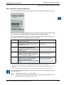
3.20.4 PCD7.D16x Small terminal kits ................................................................. 3-63
3.21 Interrupt inputs ................................................................................................ 3-64
3.21.1 Basics ......................................................................................................... 3-64
3.21.2 PCD1.M120/M130 and PCD1.M125/M135 ................................................ 3-64
3.21.3 PCD2.M120/M150/M170 ............................................................................ 3-65
3.21.4 PCD2.M480 ................................................................................................ 3-65
3.22 Run/Stop or Run/Halt switch (PCD2.M170/M480 only) .................................. 3-67
3.23 HALT switch on PCD1.M125 and PCD1.M135 ............................................... 3-68
3.23.1 HALT switch on PCD1.M125 and PCD1.M135 as input ............................. 3-68
3.24 Storing data in EEPROM ................................................................................ 3-69
3.25 Resetting the outputs on STOP or HALT (PCD2 only) .................................... 3-70

Saia-Burgess Controls AG
Manual PCD 1 / PCD 2 Series │ Document 26 / 737 EN24 │ 2014-07-30
Content
0-3
0
3.26 Presence/voltage monitoring for expansion unit (PCD2 only) ........................ 3-71
4 Saia PCD
®
Classic communication interfaces
4.1 General informations ...................................................................................... 4-1
4.1.1 Outphased interface modules .................................................................... 4-1
4.1.2 SBC S-Net .................................................................................................. 4-2
4.2 SummaryofPCD1 / PCD2onboardinterfaces ................................................ 4-3
4.3 Summary of PCD1 plug-in interface modules ................................................. 4-4
4.4 Summary of PCD2 plug-in interface modules ................................................. 4-5
4.5 Onboard interfaces ......................................................................................... 4-6
4.5.1 PGUconnection(PORT# 0,PCD1andPCD2)(RS-232)forconnectingpro-
gramming devices ...................................................................................... 4-6
4.5.2 PGUconnection(PORT# 0,PCD1andPCD2)(RS-232)
as communication interface ........................................................................ 4-7
4.5.3 PGUconnection(PORT# 0,onlyonPCD2.M1x0)(RS-485)
as communication interface ........................................................................ 4-8
4.5.4 RS-485 communicationinterfacePORT# 1,onlyonPCD1.M110 .............. 4-9
4.5.5 RS-485communiactioninterfacePORT# 6,onlyonPCD2.M480 ............. 4-10
4.5.6 USB interface as PGU interface. on PCD2.M480 ...................................... 4-11
4.5.7 ProS-NetonPCD2.M480 ........................................................................ 4-12
4.6 Plug-in interfaces modules: Socket A .............................................................. 4-13
4.6.1 RS-485 / 422withPCD7.F110,Port#1(withPCD1.M110hard-wired) ....... 4-13
4.6.2 RS-232 with PCD7.F120 (suitable for modem), Port #1
(without PCD1.M110) ................................................................................. 4-15
4.6.3 RS-232 with PCD7.F121, Port #1 (without PCD1.M110) ............................ 4-16
4.6.4 Current loop with PCD7.F130, Port #1 (without PCD1.M110) .................... 4-17
4.6.5 RS-485 with PCD7.F150, Port #1 (without PCD1.M110) ............................ 4-19
4.6.6 MP-Bus with PCD7.F180, Port #1 (without PCD1.M110) ........................... 4-20
4.6.7 Modem communication .............................................................................. 4-22
4.7 Serial interfaces: socket B(1) or B2 ............................................................... 4-23
4.7.1 RS-485 with PCD2.F520 (PCD2 only) ...................................................... 4-23
4.7.2 RS-422 with PCD2.F520 ............................................................................ 4-25
4.7.3 RS-232withPCD2.F520 / F522 .................................................................. 4-27
4.7.4 RS-232 full with PCD2.F522 (suitable for modem) .................................... 4-30
4.8 EthernetTCP / IP ............................................................................................. 4-32
4.9 Probus ........................................................................................................... 4-33
4.9.1 ProbusDPMaster,modulePCD7.F750 ................................................... 4-34
4.9.2 ProbusDPSlave,modulePCD7.F77x ..................................................... 4-36
4.9.4 ProbusFMS,modulePCD7.F700 ............................................................ 4-38
4.10 LonWorks
®
(freelycongurableLONnodes) .................................................. 4-40

Saia-Burgess Controls AG
Manual PCD 1 / PCD 2 Series │ Document 26 / 737 EN24 │ 2014-07-30
Content
0-4
0
4.11 Connection module for MP-Bus PCD2.T500 .................................................. 4-42
4.11.1 Communications signals ............................................................................ 4-42
4.11.2 Controls on PCD2.T500 ............................................................................. 4-42
4.11.3 Connection and wiring ................................................................................ 4-43
4.11.4 Supply possibilities ..................................................................................... 4-44
4.11.5 Congurationexamples.............................................................................. 4-45
4.11.6 Communications times for MP-Bus ............................................................ 4-46
4.11.7 Calculation of line length ............................................................................ 4-46
4.11.8 Maximum line length for 24 VAC supply .................................................... 4-47
4.11.9 Maximum line length for 24 VDC supply ..................................................... 4-47
4.11.10 Maximum line length for 24 VAC supply (in situ) ........................................ 4-48
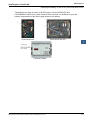
5 Input/output (I/O) modules
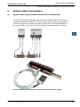
6 System cables and adapters
6.1 System cables with I/O module connections to the Saia PCD
®
..................... 6-1
7 Maintenance
7.1 Changing the battery on the PCD1.M13x and PCD2.Mxxx CPUs .................. 7-1
7.2 Updatingrmware ........................................................................................... 7-3
7.2.1 UpdatingrmwareonthePCD2.M110/M120 ............................................. 7-3
7.2.2 UpdatingrmwareonthePCD2.M150....................................................... 7-3
7.2.3 UpdatingrmwareonthePCD1.M1x5,PCD2.M170andPCD2.M480...... 7-3
A Appendix
A.1 Icons ............................................................................................................... A-1
A.2 Denitionsofserialinterfaces ......................................................................... A-2
A.2.1 RS-232 ....................................................................................................... A-2
A.2.3 TTY / currentloop ........................................................................................ A-4
A.3 Protocols on serial ports ................................................................................. A-5
A.3.1 Protocolssupportedbythermware .......................................................... A-5
A.3.2 Protocols implemented in the user program............................................... A-5
A.4 Order codes .................................................................................................... A-6
A.5 Contact ............................................................................................................ A-11

Saia-Burgess Controls AG
Manual PCD 1 / PCD 2 Series │ Document 26 / 737 EN24 │ 2014-07-30
Content
0-5
0

Saia-Burgess Controls AG
Manual PCD 1 / PCD 2 Series │ Document 26 / 737 EN24 │ 2014-07-30
Document history
Content
0-6
0
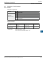
0.1 Document History
Date Version Changes Remarks
EN11a 2004-12-24 Whole Doc.
Chapt.
4.8.1
Page 57
- translation from D11
-errorinProbus:4.8.1new
- error in formulas: Page 57
EN12 2005-02-01 Chapt. 0
Chapt. 1
Chapt. 3
- error in index (Acrobat)
- error in graphical index M480
- watch-Dog IL-Example.: new
EN13 2005-10-11 Chapt. 5 - corrected error in pin allocation PCD2.A465
EN14 2007-07-25 Chapt. 3
Chapt. 4
Chapt. 5
Chapt. A
- inserted new controllers PCD1.M1x5
- added communication modules PCD7.F121
and PCD2.T500
- new order for the I/O-modules, according to
the price list
- maximal current of the I/O-modules instead of
typical current.
- added new I/O-Modules PCD2.E112,
PCD2.E116, PCD2.E613, PCD2.E616
- PCD2.A465 pinout corrected
- new TIP by PCD2.W2x0, wrong polarity on
input
- description of the Jumper positions for
PCD2.K525
- calculation of the spark deletion in the appendix
EN15 2008-07-22 Chapt. 5
Chapt. 5
- Added new module PCD2.W525
-«Denitionofinputsignals»revised
EN16 2008-12-17 Chapt. 3.4
Chapt. 5.7
Chapt.
5.12.1
Chapt. 6
Chapt. 7.1
- PCD2.M150 now with FW update
- Wiring PCD2.W2x0 corrected
- Digital / analog values PCD2.W2x0 correc-
ted
- New in its own handbook 26/792
- New indication for battery change
EN17 2009-12-15 all Conversion in CS4 and error correction
EN18 2010-02-15 Chapt. 3 New chapt. 3.12/3.13
EN19 2011-01-05 Chapt. 4 PCD7.F121 for all CPU types other than
PCD1.M110
EN20 2011-06-01
2011-11-23
Chapt. 3 -5
Chapt.
4.1.2.
Chapt. 3-19
- External and 24V power supply of the
modules, PGND assignments
Use of SBC S-Bus
Correction HW watchdog error.
EN21 2012-03-29
2012-06-20
Chapt. 3
Chapt.
5.2.1
Chapt.3
Minimal storage temperature -20 °C ➞ -25 °C
PCD2.E112 not PCD2.E113
User memory HW version <H
EN22 2013-04-23
2013-11-26
Chapt. 4
-
- internal wiring PCD2.K111
- new logo and new company name
EN23 2014-07-22 Cht. 5.2.3 Changed wrong connection diagramm
EN24 2014-07-30 Chapt. 5 Chapter 5 outsourced to doc.: 27-600

Saia-Burgess Controls AG
Manual PCD 1 / PCD 2 Series │ Document 26 / 737 EN24 │ 2014-07-30
Trademarks
Content
0-7
0
0.2 Brands and trademarks
Saia PCD
®
and Saia PG5
®
are registered trademarks of Saia-Burgess Controls AG.
Technicalmodicationsarebasedonthecurrentstate-of-the-arttechnology.
Saia-Burgess Controls AG, 2003
©
All rights reserved.
Published in Switzerland

Saia-Burgess Controls AG
Manual PCD 1 / PCD 2 Series │ Document 26 / 737 EN24 │ 2014-07-30
PCD1.M1xx
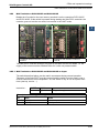
Graphical index
1-1
1
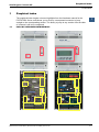
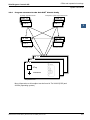
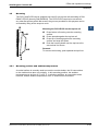
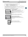
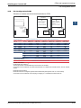
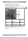
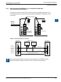
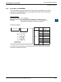
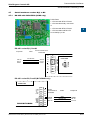
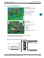
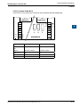
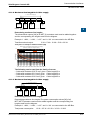
1 Graphical index
The graphical index singles out some highlights from the Hardware manual for the
PCD1/PCD2 Series, and allows you to click on a component/connector to jump
straight to the corresponding section. The facility to jump to any section from the table
of contents is still to be completed.
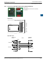
1.1 PCD1.M110/M120/M130/M125/M135


Saia-Burgess Controls AG
Manual PCD 1 / PCD 2 Series │ Document 26 / 737 EN24 │ 2014-07-30
Guidance
2-1
Introduction
2
2 Guidance
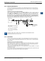
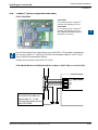
2.1 Introduction
This manual covers the technical aspects of the PCD1 and PCD2 components. The
following terms are used frequently:
● CPU Centralprocessingunit:theheartoftheSaiaPCD
®
● RIOs RemoteI/Os:inputsandoutputsconnectedtotheCPUviaa
eldbussuchasProbus
● LIOs LocalI/Os:theseareconnectedtotheCPUviatheI/Obusora
RIO(i.e.withtheshortestpossiblecables)
● Modules Input/outputelements,mountedinahousing,matchedtothe
PCD1/2system
● Moduleholders CPUs,RIOsorLIOs,towhichmodulesmaybeattached
TheaimoftheOverviewsectionistopresenttheessentialsofplanningandinstalling
controlsystemswithPCD1/2components.Itcoversthefollowingtopics:
● Planning an application
● Cabling
Detailsofhardware,software,conguration,maintenanceandtroubleshootingare
describedinseparatesections.

Saia-Burgess Controls AG
Manual PCD 1 / PCD 2 Series │ Document 26 / 737 EN24 │ 2014-07-30
Guidance
2-2
PlanninganapplicationwithPCD1/2/3components
2
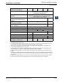
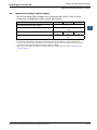
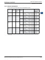
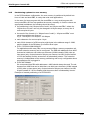
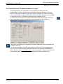
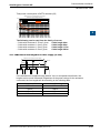
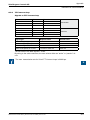
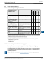
2.2 Planning an application with PCD1/2/3 components
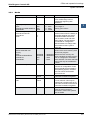
ThefollowingaspectsshouldbeconsideredwhenplanningPCD1/2applications:
● TheinternalloadcurrenttakenbytheI/Omodulesfromthe+5VandV+supply
mustnotexceedthemaximumsupplycurrentspeciedfortheCPUs
● TheCPUtypedeterminesthemaximumnumberofmodules
● ThetotallengthoftheI/Obusislimitedbytechnicalfactors;theshorter,thebetter
When planning an application, we recommend the following procedure:
SelecttheI/Omodulesaccordingtorequirements.
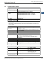
Checkthatthenumberofmodulesisallowed:
PCD
Type
Max.numberofI/Omodules Max.number¹)ofdigitalI/Os
PCD1/
PCD2
CPU
PCD2
expan-
sion
PCD3
expan-
sion
Total PCD1/
PCD2
CPU
Expan-
sion
Total
PCD1 4 – – 4 64 – 64
PCD2.M120/150 8 8 8 16 128 128(-1) 256(-1)
PCD2.M170 8 8 24 32 128 384(-2) 512(-2)
PCD2.M480 8 8 56 64 128 896(-1) 1024(-1)
¹)PCD2modulesandPCD3moduleswith16I/Oseach
Thevaluesinbracketshavetobesubtractedfromthemaximumnumberofdigital
I/Osbecauseofthewatchdogrelay.
IfyouwanttoexpandPCD2CPUswithPCD3LIOs/RIOs,pleaserefertothe
planninginstructionsinthePCD3manual.
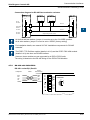
Ifthenumberofmodulesisallowed,continuefrom;ifnot,selectadifferentCPU
Ifnecessary,selectthePCD2expansionhousing:
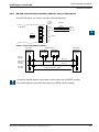
● PCD2.C100 with8modulesockets
● PCD2.C150 with4modulesockets
● PCD2.K100 26-coreextensioncableforconnectingPCD2baseunits
mountedbeneatheachother.
● PCD2.K110 26-coreextensioncableforconnectingPCD2baseunits
mountedside-by-side.
● PCD2.K120 26-coreextensioncableforspecicapplications(length2m).
● PCD2.K106 26-coreextensioncableforconnectingPCD2CPUswith
PCD3moduleholders.
WherePCD2.WxxxandPCD2.Hxxxmodulesareused,calculatetheload
currentfromtheinternal+5VandV+supply(usetheworst-case/highest
values)

Saia-Burgess Controls AG
Manual PCD 1 / PCD 2 Series │ Document 26 / 737 EN24 │ 2014-07-30
Guidance
2-3
PlanninganapplicationwithPCD1/2/3components
2
Checkthatthemax.supplycurrentfortheCPUissufcient;itgenerallyshould
be.Inextremecases,switchtoPCD3expansionunits.
Estimate consumption from the 24 Vsupply.Useestimatedvaluesfromthe
section on “Hardware”.
Theseestimatedvaluescanbefoundinsection3.8.5,“Powerconsumptionof
PCD2/PCD3input/outputmodules”.
Note that in most applications the outputs place the heaviest load on the 24 Vsup-
ply.For16outputswithaloadcurrentof0.5 Aeach,theloadingwillbe8 A with all
outputs connected.

Saia-Burgess Controls AG
Manual PCD 1 / PCD 2 Series │ Document 26 / 737 EN24 │ 2014-07-30
Guidance
2-4
Cabling
2
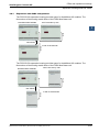
2.3 Cabling
2.3.1 Cable routing
● 230 Vsupplylinesandsignallinesmustbelaidinseparatecablesatleast10 cm
apart.Evenwithintheswitchingcabinet,itisadvisabletoleavespacebetween
power and signal lines.
● Digitalsignal/buslinesandanaloguesignal/sensorlinesshouldbelaidin
separatecables
● Itisadvisabletouseshieldedcablesforanaloguesignallines.
● Theshieldshouldbeearthedattheentryorexittotheswitchingcabinet.The
shieldsshouldbeasshortaspossibleandofthelargestpossiblecross-section.
Thecentralearthingpointshouldbe>10 mm² and connected to the PE ground
wirebytheshortestroute
● Theshieldisgenerallyconnectedtoonesideoftheswitchingcabinetonly,unless
thereisapotentialequalizationwithsignicantlylowerresistancethantheshield
resistance
● Inductivitiesinstalledinthesameswitchingcabinet,e.g.contactorcoils,shouldbe
providedwithsuitablesuppressors(RCelements)
● Switchingcabinetcomponentswithhigheldintensity,e.g.transformersor
frequencyinverters,shouldbeshieldedwithseparatorplateswithagoodground
connection.
Surge protection for long distances or external lines
● Wherelinesarelaidoutsidethebuilding,oroverlongerdistances,suitablesurge
protectionmeasuresshouldbeapplied.Forbuslinesinparticular,thesemeasures
are essential.
● Withlineslaidoutside,theshieldmusthaveadequatecurrent-carryingcapacity
andbeearthedatbothends.
● Thesurgeconductorsshouldbeinstalledattheinputtotheswitchingcabinet.

Saia-Burgess Controls AG
Manual PCD 1 / PCD 2 Series │ Document 26 / 737 EN24 │ 2014-07-30
CPUs and expansion housings
3-1
System overview
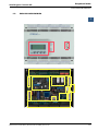
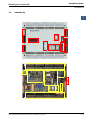
3
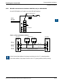
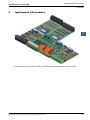
3 Saia PCD
®
Classic CPUs and expansion housings
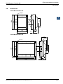
The CPUs in the xx7 Series are described in a separate manual, 26/757.
3.1 System overview
3.1.1 Outphased Saia PCD
®
s
Article Active Not recommended for
new projects
Outphased
(no longer produced)
PCD1.M110 ×
PCD1.M120 ×
PCD1.M125 ×
PCD1.M130 ×
PCD1.M135 ×
PCD1.M135F655 ×
. . .
PCD2.M110 ×
PCD2.M120 ×
PCD2.M150 ×
PCD2.M170 ×
PCD2.M170F655 ×
PCD2.M480 ×
PCD2.M480F655-2 ×
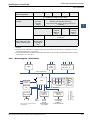
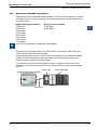
3.1.2 Saia PCD
®
Web-Server
The Saia PCD
®
controllers PCD1.M125, PCD1.M135, PCD2.M150, PCD2.M170,
PCD2.M480 and PCD3.Mxxx0 come with an integrated web server as standard:
● Webbrowserasatoolforcomissioning, support and visualization:
AccesstotheSBCWebserverisviastandardwebbrowserssuchasInternet
Explorer or Netscape Navigator. This makes the web browser, which can be
operated intuitively by anyone, the standard tool for comissioning, service,
support and visualization of machines, units and installations. The user can
retrievepre-deneddeviceandsystem-specicHTMLpages,givingaccessto
alldataoncontrollersandRIOs.Graphicalelements(images,diagramsetc.)as
well as text documents (operating and repair manuals) can also be integrated
intotheHTMLpages,toprovideapersonalizeduserinterface
● Generalaccesstoanydesiredinterfacesandnetworks:
AccesstothewebserverisavailablenotonlyviaEthernetTCP/IP,butalsovia
cost-effective standard serial interfaces (RS-232, RS-485, modem etc.) and via
Probusnetworks,throughoutthesystemandatdifferentlevelsinthenetwork.
This makes it economical to use web technology to operate and monitor even
the smallest applications.
● TheSaiaPCD
®
web server is integrated into all products:
Havingawebserverintegratedasstandardeliminatesthecostofrun-time
licensesoradditionalmodules.InthePCD3controllersenumeratedabove
andthePCD3RIOs,thewebserverisalreadyincludedinthebaseunits,atno
extra cost.

Saia-Burgess Controls AG
Manual PCD 1 / PCD 2 Series │ Document 26 / 737 EN24 │ 2014-07-30
CPUs and expansion housings
3-2
Generaltechnicaldetails
3
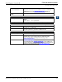
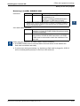
3.2 General technical details
Supply (external and internal)
Supply voltage
(accordingEN/IEC61131-2)
24 VDC -20 / +25% incl. 5% ripples
Power consumption
1)
PCD1andPCD2:typically625mA/15Wfor64I/Os
PCD2:typically833mA/20Wfor128I/Os
Capacity of internal
5 V bus
2)
PCD1: 750 mA
PCD2.M110/M120hardwareversion<H:1100mA
PCD2.M110/M120hardwareversion>=H:1600mA
PCD2.M150: 1600 mA
PCD2.M170: 1600 mA
PCD2.M480: 2000 mA
Capacity of internal +V bus
(16…24 V)
2)
PCD1: 100 mA
PCD2: 200 mA
Short voltage interruptions
(accordingEN/IEC61131-2)
)
≤10mswithinterval≥1s
1)Theloadsontheoutputsaregenerallymoresignicantforsizingthesupplythantheinternalpowerleakage
within the controller
2)WhenplanningPCD2systems,itisessentialtocheckthatthetwointernalsuppliesarenotoverloaded.This
check is especially important where analogue, counter and motion control modules are used, as these may con-
sume a lot of power.
Atmospheric conditions
Ambient
temperature
Mounting on vertical surface with vertically aligned connection
terminals:0 … +55°C
Inallothermountingpositions,areducedtemperaturerangeof
0 … +40°Capplies
Storage temperature -25 … +85°C
Relative humidity 30 … 95%withoutcondensation
Vibration resistance
Vibration accordingtoEN/IEC61131-2:
5 … 13.2Hzconstantamplitude1.42mm
13.2 … 150Hz,constantacceleration(simplegravitational
acceleration)
Electrical safety
Protection type IP20accordingtoEN60529
Air/leakage paths according to EN61131-2 and EN50178: between circuits and
bodies and between electrically isolated circuits: surge category
II,foulinglevel2
Test voltage 350V/50HzACfornominalunitvoltage24VDC
Electromagnetic compatibility
Electrostatic discharge according to EN61000-4-2: 8 kV: air discharge
8 kV: contact discharge
Electromagneticelds accordingtoEN61000-4-3: eldintensity10V/m,
80 … 1000MHz
Bursts according to EN61000-4-4: 4 kV on DC supply lines,
1/2kVonI/Osignallines,
1 kV on interface lines
Noise emission PCD1,
PCD2.M110/M120/M170
according to EN50 081-1: Class B (residential areas)

Saia-Burgess Controls AG
Manual PCD 1 / PCD 2 Series │ Document 26 / 737 EN24 │ 2014-07-30
CPUs and expansion housings
3-3
Generaltechnicaldetails
3
Noise emission
PCD2.M150/M480
according to EN50081-2: Class A (for industrial areas)
Guidanceonthecorrectuseofthesecontrolsinresidential
areas can be found at www.sbc-support.com (additional
measures).
Noise immunity PCD1/
PCD2
according to EN50082-2
Mechanism and mounting
Housingmaterial Base:
Cover:
Fibre optics: PC, crystal-clear
Mounting rail Double top-hat rail as per EN50022-35 (2 x 35 mm)
Connections
Screw terminals Unlessspeciedotherwise:forwiresof1.5mm
2
(AWG16)or
2 x 0.5 mm
2
(2xAWG20)
Plug-in screw terminals Theterminalblockmayonlybepluggedonto20times.Itmust
then be replaced, to guarantee a reliable contact
Standards / approvals
EN/IEC EN/IEC61131-2“Programmablecontrollers”
Shipbuilding ABS,BV,DNV,GL,LRS,PRS.
Please verify if your chosen product is mentioned in the
list of corresponding Type-Approval-Company under
www.sbc-support.com.
cULus-listed Please verify if your chosen product is listed in the correspond-
ingCerticateunderwww.sbc-support.com. The condition for
cULusCompliancearementionedonthesheetannexedtothe
product or can be required under www.sbc-support.com.

Saia-Burgess Controls AG
Manual PCD 1 / PCD 2 Series │ Document 26 / 737 EN24 │ 2014-07-30
CPUs and expansion housings
3-4
System resources
3
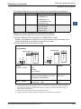
3.3 System resources
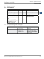
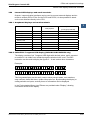
3.3.1 Program blocks
Type Number Addresses Remarks
Cyclic organization blocks
(COB)
16 0…15 Main program elements
Exception/system-dependent
organization blocks (XOB)
32 0…31 called from the system
Program blocks (PB) 300 0…299 Sub-programs
Function blocks (FB) 1000 0…999 Sub-programs with parameters
Sequential blocks (SB)
PCD1, PCD2.M110/M120/M150:
total 2000 steps and transitions
each
PCD2.M170, PCD2.M480:
total 6000 steps and transitions
each(withPG5≥1.2and
rmwareversion≥010)
32
96
0…31
0…95
forGraftecprogrammingof
sequential processes
3.3.2 Computation ranges for count types
Type Remarks
Integers – 2,147,483,648 to
+ 2,147,483,647
Format: decimal, binary, BCD or
hexadecimal
Floating point numbers –9.22337x10
18
to
– 5.42101 x 10
-20
+9.22337x10
18
to
+ 5.42101 x 10
-20
Instructionsareprovidedto
convert values held in SBC
format (Motorola Fast Floating
Point,FFP)toIEEE754format
and vice versa.
Page is loading ...
Page is loading ...
Page is loading ...
Page is loading ...
Page is loading ...
Page is loading ...
Page is loading ...
Page is loading ...
Page is loading ...
Page is loading ...
Page is loading ...
Page is loading ...
Page is loading ...
Page is loading ...
Page is loading ...
Page is loading ...
Page is loading ...
Page is loading ...
Page is loading ...
Page is loading ...
Page is loading ...
Page is loading ...
Page is loading ...
Page is loading ...
Page is loading ...
Page is loading ...
Page is loading ...
Page is loading ...
Page is loading ...
Page is loading ...
Page is loading ...
Page is loading ...
Page is loading ...
Page is loading ...
Page is loading ...
Page is loading ...
Page is loading ...
Page is loading ...
Page is loading ...
Page is loading ...
Page is loading ...
Page is loading ...
Page is loading ...
Page is loading ...
Page is loading ...
Page is loading ...
Page is loading ...
Page is loading ...
Page is loading ...
Page is loading ...
Page is loading ...
Page is loading ...
Page is loading ...
Page is loading ...
Page is loading ...
Page is loading ...
Page is loading ...
Page is loading ...
Page is loading ...
Page is loading ...
Page is loading ...
Page is loading ...
Page is loading ...
Page is loading ...
Page is loading ...
Page is loading ...
Page is loading ...
Page is loading ...
Page is loading ...
Page is loading ...
Page is loading ...
Page is loading ...
Page is loading ...
Page is loading ...
Page is loading ...
Page is loading ...
Page is loading ...
Page is loading ...
Page is loading ...
Page is loading ...
Page is loading ...
Page is loading ...
Page is loading ...
Page is loading ...
Page is loading ...
Page is loading ...
Page is loading ...
Page is loading ...
Page is loading ...
Page is loading ...
Page is loading ...
Page is loading ...
Page is loading ...
Page is loading ...
Page is loading ...
Page is loading ...
Page is loading ...
Page is loading ...
Page is loading ...
Page is loading ...
Page is loading ...
Page is loading ...
Page is loading ...
Page is loading ...
Page is loading ...
Page is loading ...
Page is loading ...
Page is loading ...
Page is loading ...
Page is loading ...
Page is loading ...
Page is loading ...
Page is loading ...
Page is loading ...
Page is loading ...
Page is loading ...
Page is loading ...
Page is loading ...
Page is loading ...
Page is loading ...
Page is loading ...
Page is loading ...
Page is loading ...
Page is loading ...
Page is loading ...
Page is loading ...
Page is loading ...
Page is loading ...
Page is loading ...
Page is loading ...
Page is loading ...
Page is loading ...
-
 1
1
-
 2
2
-
 3
3
-
 4
4
-
 5
5
-
 6
6
-
 7
7
-
 8
8
-
 9
9
-
 10
10
-
 11
11
-
 12
12
-
 13
13
-
 14
14
-
 15
15
-
 16
16
-
 17
17
-
 18
18
-
 19
19
-
 20
20
-
 21
21
-
 22
22
-
 23
23
-
 24
24
-
 25
25
-
 26
26
-
 27
27
-
 28
28
-
 29
29
-
 30
30
-
 31
31
-
 32
32
-
 33
33
-
 34
34
-
 35
35
-
 36
36
-
 37
37
-
 38
38
-
 39
39
-
 40
40
-
 41
41
-
 42
42
-
 43
43
-
 44
44
-
 45
45
-
 46
46
-
 47
47
-
 48
48
-
 49
49
-
 50
50
-
 51
51
-
 52
52
-
 53
53
-
 54
54
-
 55
55
-
 56
56
-
 57
57
-
 58
58
-
 59
59
-
 60
60
-
 61
61
-
 62
62
-
 63
63
-
 64
64
-
 65
65
-
 66
66
-
 67
67
-
 68
68
-
 69
69
-
 70
70
-
 71
71
-
 72
72
-
 73
73
-
 74
74
-
 75
75
-
 76
76
-
 77
77
-
 78
78
-
 79
79
-
 80
80
-
 81
81
-
 82
82
-
 83
83
-
 84
84
-
 85
85
-
 86
86
-
 87
87
-
 88
88
-
 89
89
-
 90
90
-
 91
91
-
 92
92
-
 93
93
-
 94
94
-
 95
95
-
 96
96
-
 97
97
-
 98
98
-
 99
99
-
 100
100
-
 101
101
-
 102
102
-
 103
103
-
 104
104
-
 105
105
-
 106
106
-
 107
107
-
 108
108
-
 109
109
-
 110
110
-
 111
111
-
 112
112
-
 113
113
-
 114
114
-
 115
115
-
 116
116
-
 117
117
-
 118
118
-
 119
119
-
 120
120
-
 121
121
-
 122
122
-
 123
123
-
 124
124
-
 125
125
-
 126
126
-
 127
127
-
 128
128
-
 129
129
-
 130
130
-
 131
131
-
 132
132
-
 133
133
-
 134
134
-
 135
135
-
 136
136
-
 137
137
-
 138
138
-
 139
139
-
 140
140
-
 141
141
-
 142
142
-
 143
143
-
 144
144
-
 145
145
-
 146
146
-
 147
147
-
 148
148
-
 149
149
-
 150
150
-
 151
151
-
 152
152


Ask a question and I''ll find the answer in the document
Finding information in a document is now easier with AI
Related papers
-
SBC Saia PCD® Supervisor V1.0 Owner's manual
-
-
-
-
-
-
-
-
-
Other documents
-
Ground Zero GZDSP 4.60ISO Owner's manual
-
Compaq PCD-1 Supplementary Manual
-
Vaisala GML20T User manual
-
-
 Saia-Burgess Controls Ltd. PCD7.D6120TV010 User manual
-
3M M170 User manual
-
ICP DAS USA I-7550 User manual
-
KarliK DSR-1 User manual
-
 Badger Meter F110 Instruction And Operation Manual
-
Danfoss ECL Comfort 200/300 User guide

