
AHF 005/010
■ Contents
Safety
.................................................................................................................... 2
Warnings ................................................................................................................ 2
Symbols used in this manual .................................................................................. 2
Operator’s safety .................................................................................................... 2
Avoid filter module d amage .................................................................................... 2
DC-link resonance ................................................................................................. 2
Description ........................................................................................................ 3
Description ............................................................................................................. 3
Ordering numbers, 380 - 415 V, 50 Hz ................................................................... 4
Ordering numbers, 440 - 480 V, 60 Hz ................................................................... 5
Ordering numbers, 500 V, 50 Hz ............................................................................ 5
Calculation of the exact filter size needed ............................................................... 6
Specifications ................................................................................................... 7
General t echnical data ............................................................................................ 7
Environmental data ................................................................................................. 8
Dimensions/weight ................................................................................................. 9
Dimension diagrams ............................................................................................... 11
Installation ......................................................................................................... 14
Mechanical installation ............................................................................................ 14
Ventilation ............................................................................................................... 14
Power wiring .......................................................................................................... 14
Over tem p erature contactor ................................................................................... 16
Power wiring size .................................................................................................. 16
Operation on different mains type ................................................................... ........ 17
Typical installation in a panel or other enclosures .................................................... 18
Commissioning ...................................................................................... ......... 19
Commissioning ...................................................................................................... 19
Appendix: Safety and application notes for ............................. ........ 20
1. General .............................................................................................................. 20
2. Application as directed ....................................................................................... 20
3. Transport, Storag e .................................................................................... ......... 20
4. Installation .......................................................................................................... 20
5. Electrial Installa tion ............................................................................................. 20
6. Operation ........................................................................................................... 21
7. Maintenance and service ................................................................................... 21
MG.80.B3.22 - VLT is a registered Danfoss trademark
1

AHF 005/010
■Warnings
The Danfoss harmonic filter AHF 005 and
AHF 010 contain dangerous voltages
when connected to line voltages. Only
a competent electrician should carry out the
electrical installation. Improper installation of the
filter module or the connected frequency converter
may caus e equipment failure, serious injury or
death. Follow this manual and National Electrical
Codes and local sa fety codes.
Operatio n of the harmonic filter is only al lowed
with a closed cover of the housing!
■Symbols used in this manual
When you read this manual you will c ome ac ross
different symbols that require special attention.
The symbols used are the following:
Warning of hazardous electrical voltage
Warning of a general dang er
NOTE
This note designates general, useful notes. If
you observe it, handling of the filter module
/ drive system is made easier.
■Operator’s safety
After mains disconnections, the power
terminals X1.1, X1.2, X1.3, X3.1 , X3.2,
X3.3, X4.1, X4.2 and X4.3 remain
live for minimum 15 minutes .
The filter module s have to be installed
in a way, that they fulfil their function
and don’t expose persons to dan ger.
They have to be mounted correctly and used in
accordance with their purpose.
■Avoid filter module damage
1. Thefiltermodulesaretobeusedonlywith
Danfoss frequency converters. The usage
with other electrical loads is not permitted
and may damage the devices .
2. Don’t use the drive s ystem (frequency converter,
motor load and filter module) if the equipment
has been damaged.
3. Modifications of the filter modules are not allowed.
■DC-link resonance
To avoid resonance’s in the DC-link, it is possible t o
disable the dynamic DC link compensation.
483 Dynamic DC link compensation
(DC LINK COMP.)
Value:
Off
[0]
✭On
[1]
Function:
The VLT 5000, 6000 and 8000 series include a feature,
which ensures that the output voltage is independent
of any voltage fluctuation in the DC link, e.g. caused
by fa st fluctuation in the mains supply voltage. The
benefit is a very steady torque on motor shaft (low
torque ripple) under most mains conditions.
Description of choice:
In some cases this very dynamic compensation can
cause resonance’s in the DC link and should then
be disabled. Typical cases are where a line choke or
a passive harmonic filter (e.g. filters AHF005/010)
is mounted in the mains supply to the frequency
converter to suppress harmonics. Can also occur
on mains with l ow short circuit ratio.
MG.80.B3.22-VLTisaregisteredDanfosstrademark
2

AHF 005/010
Description
■Description
The Danfoss harmonic filters AHF 005 and AHF 010
are ensuring near sinusoidal line current minimising
the harmonic current emission into the mains supply.
The D anfoss AHF 005 and AHF 010 are advanced
harmonic filters not to be compared w ith traditional
harmonic trap filters. The Danfoss harmonic filters
have been specially designed to match all the Danfoss
frequency converters. The filters AHF 010 and AHF
005 are available in three vo ltage ratings.
• 380 - 415 V AC
• 440 - 480 V AC
• 500 V AC
The D anfoss AHF 010 and AHF 005 have the
following characteristics:
• Small compact housing that fits into a pane l
• Easy to use in retrofit applications
• AHF 010 reduces the total harmonic current
distortion to 10%*
• AHF 005 reduces the total harmonic current
distortion to 5%*
• Current rating from 10A - 370A
• For higher power modules can be paralleled
• One filter module can be used for several
frequency converters
• High e fficiency (> 0.98)
• User-friendly commissioning - no adjustment
necessary
• No routine maintenance required
* THiD of 10% or 5% will be achie ved when the
following cond itions are met:
- THvD of the system without the drive
operating is less than 2%
- Filter is operating a t nominal load
If these conditions are not fulfilled, a significant reduction
of the harmonic components can still be achieved, but
the rated THiD values may not be achieved.
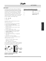
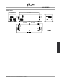
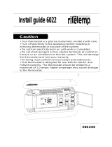
Principle connection diagram of the
Danfoss harmonic filter.
L
egends (as u sed throughout this m anual):
U
L
:Linevoltage
I
AHF
: Input current of the filter
AHF
I
FC,L
: Input current to the
frequency converter
I
M
: Motor current
MG.80.B3.22 - VLT is a registered Danfoss trademark
3

AHF 005/010
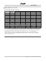
■Ordering numbers, 380 - 415 V, 50 Hz
AHF 005 and AHF 010, 380V - 415V, 50Hz
Danfoss ordering number Typical Danfoss frequency converter seriesI
AHF,N
Typical Motor
Used [kW]
AHF 005 AHF 010 VLT 5000 VLT 6000 HVAC VLT 8000AQUA
10 A 4, 5.5 175G6600 175G6622 5006, 5008 6006, 6008 8006, 8008
19 A 7.5 175G6601 175G6623 5011 6011 8011
26 A 11 175G6602 175G6624 5016 6016 8016
35 A 15, 18.5 175G6603 175G6625 5022, 5027 6022, 6027 8022, 8027
43 A 22 175G6604 175G6626 5032 6032 8032
72 A 30, 37 175G6605 175G6627 5042, 5052 6042, 6052 8042, 8052
101 A 45, 55 175G6606 175G6628 5062, 5072 6062, 6072 8062, 8072
144 A 75 175G6607 175G6629 5102 6102 8102
180 A 90 175G6608 175G6630 5122 6122 8122
217 A 110 175G6609 175G6631 5152 6152 8152
289 A 132, 160 175G6610 175G6632 5202, 5252 6172, 6222 8202, 8252
324 A 175G6611 175G6633
370 A 200 175G6688 175G6691 5302 6272 8302
Higher ratings can be achieved by paralleling the filter units
434 A 250 Two 217A units 5350 6352 8352
578 A 315 Two 289 A units 5450 6400 8450
613 A 355 289 A and 324 A u nits 5500 6500 8500
Please note that the matching of the typical Danfoss frequency converter and filter is pre-calculated based
on 40 0V and assuming typical mot or load (4 or 2 pole motor). VLT 5000 series is based on a max. 160 %
torque application, while VLT 6000 and 8000 series are based on a max. 110% torque application.
The pre-calculated filter current may be different than the input current ratings of VLT 5000, VLT 6000
and VLT 8000 series as s tated in the respective operating instructions, as these numbers are b ased on
different operating conditions.
MG.80.B3.22-VLTisaregisteredDanfosstrademark
4

AHF 005/010
Description
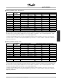
■Ordering numbers, 440 - 480 V, 60 Hz
Danfoss ordering number Typical Danfoss frequency converter seriesI
AHF,N
Typical Motor
Used [HP]
AHF 005 AHF 010 VLT 5000 VLT 6000 HVAC VLT 8000 AQUA
19 A 10, 15 175G6612 175G6634 5011, 5016 6011, 6016 8011, 8016
26 A 20 175G6613 175G6635 5022 6022 8022
35 A 25, 30 175G6614 175G6636 5027, 5032 6027, 6032 8027, 8032
43 A 40 175G6615 175G6637 5042 6042 8042
72 A 50, 60 175G6616 175G6638 5052, 5062 6052, 6062 8052, 8062
101 A 75 175G6617 175G6639 5072 6072 8072
144 A 100, 125 175G6618 175G6640 5102, 5122 6102, 6122 8102, 8122
180 A 150 175G6619 175G6641 5152 6152 8152
217 A 200 175G6620 175G6642 5202 6172 8202
289 A 250 175G6621 175G6643 5252 6222 8252
324 A 300 175G6689 175G6692 5302 6272 8302
370 A 350 175G6690 175G6693 5350 6352 8352
Higher ratings can be achieved by paralleling the filter units
506 A 450 217 A and 289 A u nits 5450 6400 8450
578 A 500 Two 289 A units 5500 6500 8500
648 A 600 Two 324 A units - 6550 8600
Please note that the matching of the typical Danfoss frequency converter and filter is pre-calculated based
on 480V and a ssuming typical motor load. VLT 5000 series is based on a 160 % torque application, while
VLT 6000 and 8000 series are based on 110% torque application.
The pre-calculated filter current may be varying from the input current ratings of VLT 5000, VLT 6000 and
VLT 8000 series as stated in the respective o perating instructions, as these numbers are based on different
operating conditions.
■Ordering numbers, 500 V, 50 Hz
Danfoss ordering number Typical Danfoss frequency converter seriesI
AHF,N
Typical Motor
Used [kW]
AHF 005 AHF 010 VLT 5000 VLT 6000 HVAC VLT 8000 AQUA
10 A 4, 5.5 175G6644 175G6656 5006, 5008 6006, 6008 8006, 8008
19 A 7.5, 11 175G6645 175G6634 5011, 5016 6011, 6016 8011, 8016
26 A 15, 18.5 175G6646 175G6635 5022, 5027 6022, 6027 8022, 8027
35 A 22 175G6647 175G6636 5032 6032 8032
43 A 30 175G6648 175G6637 5042 6042 8042
72 A 37, 45 175G6649 175G6638 5052, 5062 6052, 6062 8052, 8062
101 A 55, 75 175G6650 175G6639 5062, 5072 6062, 6072 8062, 8072
144 A 90, 110 175G6651 175G6640 5102, 5122 6102, 6122 8102, 8122
180 A 132 175G6652 175G6641 5152 6152 8152
217 A 160 175G6653 175G6642 5202 6172 8202
289 A 200 175G6654 175G6643 5252 6222 8252
324 A 250 175G6655 175G6692 5302 6302 8302
Higher ratings can be achieved by paralleling the filter units
434 A 315 Two 217 A units 5350 6352 8352
469 A 355 180 A and 289 A u nits 5450 6400 8450
578 A 400 Two 289 A units 5500 6500 8500
Please note that the matching of the typical Danfoss frequency converter and filter is pre-calculated based
on 500V and assuming typical motor load
. VLT 5000 series is based on a 160 % torque application, while
VLT 6000 and 8000 series are based on 110% torque application.
The pre-calculated filter current may be varying from the input current ratings of VLT 5000, VLT 6000 and
VLT 8000 series as stated in the res
pective operating instruc tions, as these numb ers are based on different
operating conditions.
MG.80.B3.22 - VLT is a registered Danfoss trademark
5

AHF 005/010
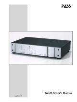
■Calculation of the exact filter size needed
For op timal p erform a nce the harmonic filter should
be sized for the line input current to the frequency
converter, i.e. the input current drawn based on the
expected load of the frequency converter and not
the size of the frequency converter itself!
The line input current to the frequency converter
(I
FC,L
) can by calculated using the nominal motor
current (I
M,N
) and displacement powe r factor (Cos
φ)) of the motor. Both data are normally printed
on the nam eplate of the motor. In the case where
the nominal motor voltage (U
M,N
) is unequal to the
actual line-line voltage (U
L
) the calculated current
must be corrected with the ratio between these
voltages as shown in the equation below.
Theharmonicfilterchosenmusthaveanominal
current (I
AHF,N
) equal to or larger than the calculated
frequency converter line input current (I
FC,L
).
If several frequency converters are to be connected
to the same filter, the harmonic filter must be sized
according to the sum o f the calculated line currents.
If the harmonic filter is sized for the load, and
the motor of the correspon ding frequen cy
conver ter is cha nged, th e current must be
re-calculat ed to avoid ov erload of the harmonic filter.
MG.80.B3.22-VLTisaregisteredDanfosstrademark
6

AHF 005/010
Specifications
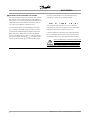
■General technical data
AHF 0xx AHF 0xx AHF 0xx
Nominal supply
voltage
U
L,N
[V] 380 ≤ U
L,N
≤ 415 440 ≤ U
L,N
≤ 480 500 V
Tolerance of the
actual supply
voltage
U
L
[V] 342 ≤ U
L
≤ 456 396 ≤ U
L
≤ 528 450 ≤ U
L
≤ 550
Supply frequency f
L,N
[Hz] 50 ± 5 % 60 ± 5 % 50 ± 5 %
Overload capability 1,6 for 60s
Efficiency η[%] ~98.8%
THiD [%] AHF 005 < 5%
AHF 010 < 10%
cos φ of I
L
0.5 cap
0.8 cap
0.85 cap
0.99 cap
1.00
at 25% I
AHF,N
at 50% I
AHF,N
at 75% I
AHF,N
at 100% I
AHF,N
at 150% I
AHF,N
Power derating [%/C]
[%/m]
40°C<Ta<55°C=>3%/C
1000m altitude above sea level.< h ≤ 4000m altitud e above sea
level => 5%/1000m
NOTE
The reduction of the low harmonic current
emission to the r ated THiD i mplies, that the
THvD of the non-influenced main
s voltage is
lower than 2% and the ratio of short circuit power
toinstalledload(R
SCE
) is at least 66. Under these
conditions the THiD of the ma
ins current of the
frequency converter is reduced to 10% or 5% (typical
values a t nominal load). If these conditions are not
or only partially fulf
illed, a significant reduction of the
harmonic components can still be achieved, but the
rated THiD values m ay not be achieved.
MG.80.B3.22 - VLT is a registered Danfoss trademark
7

AHF 005/010
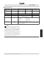
■Environmental data
Permissible
temperature range*
During transport o f the unit:
During storage of the unit:
During operation of the unit:
-25°C...+70°C (to VDE 0160)
-25°C...+55°C (to VDE 0160)
5°C...+40°C without power derating
5°C...+55°C with power derating
Humidity class* Humidity class F without condensation ( 5% - 85% relative humidity)
Installation he igh t h* H ≤ 1000 m altitude above sea level
1000 m altitude above sea level< h ≤
4000 m altitude above sea level
without power derating
with power derating
Degree of pollution VDE 0110 Part 2 degree 2
Insulation strength Overvoltage category III ac co rding to VDE 01 10
Packaging DIN 55468 for transport packaging materials
Type of protection IP 20
Approvals CE: Low-Voltage Directive; UL; C-tick
*climatic conditions according to class 3K3
(EN 50178 Part 6.1)
MG.80.B3.22-VLTisaregisteredDanfosstrademark
8

AHF 005/010
Specifications
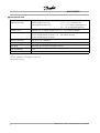
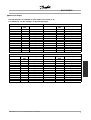
■Dimensions/weight
The AHF-modules are available in seven frame sizes (size B to H).
For dimensions see the drawings on the following pages
AHF 010, 380 – 415 V AC, 50Hz AHF 010, 440 – 480 V AC, 60Hz
I
AHF,N
Frame
size
Weight I
AHF,N
Frame
size
Weight
10 A B 15 Kg (33 lbs)
19 A B 19 Kg (42 lbs) 19 A B 20 Kg (44 lbs)
26 A B 24 Kg (52 lbs) 26 A B 25 Kg (55 lbs)
35 A C 38 Kg (84 lbs) 35 A C 38 Kg (84 lbs)
43 A C 45 Kg (99 lbs) 43 A C 45 Kg (99 lbs)
72 A D 64 Kg (141 lbs) 72 A D 64 Kg (141 lbs)
101 A D 80 Kg (176 lbs) 101 A D 81 Kg (178 lbs)
144 A D 101 Kg (222 lbs) 144 A D 103 Kg (227 lbs)
180 A E 134 Kg (295 lbs) 180 A E 135 Kg (297 lbs)
217 A E 159 Kg (350 lbs) 217 A E 161 Kg (355 lbs)
289 A F 180 Kg (396 lbs) 289 A F 191 Kg (421 lbs)
324 A F 233 Kg (513 lbs) 324 A F 232 Kg (511 lbs)
370 A G 252 Kg (555 lbs) 370 A G 245 Kg (540 lbs)
AHF 005, 380 – 415 V AC, 50Hz AHF 005, 440 – 480 V AC, 60Hz
I
AHF,N
Frame
size
Weight I
AHF,N
Frame
size
Weight
10 A B 20Kg (44 lbs)
19 A C 31 Kg (68 lbs) 19 A C 32 Kg (71 lbs)
26 A C 31 Kg (68 lbs) 26 A C 43 Kg (95 lbs)
35 A C 49 Kg (108 lbs) 35 A C 50 Kg (110 lbs)
43 A D 60 Kg (132 lbs) 43 A D 60 Kg (132 lbs)
72 A D 81 Kg (178 lbs) 72 A D 82 Kg (181 lbs)
101 A E 128Kg(282lbs) 101 A E 129 Kg (284 lbs)
144 A E 165Kg(364lbs) 144 A E 167 Kg (368 lbs)
180 A F 197Kg(434lbs) 180 A F 200 Kg (441 lbs)
217 A F 228Kg(503lbs) 217 A F 230 Kg (507 lbs)
289 A G 269Kg(593lbs) 289 A G 272 Kg (600 lbs)
324 A G 309Kg(681lbs) 324 A G 306 Kg (675 lbs)
370 A H 345Kg(760lbs) 370 A H 348 Kg (767 lbs)
MG.80.B3.22 - VLT is a registered Danfoss trademark
9

AHF 005/010
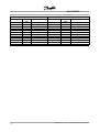
AHF 005, 500 V AC , 5 0Hz AHF 0 10 , 500 V AC, 50Hz
I
AHF,N
Frame
size
Weight I
AHF,N
Frame
size
Weight
10 A B 22 Kg (48 lbs) 10 A B 17 Kg (37 lbs)
19 A C 35 Kg (77 lbs) 19 A B 21 Kg (46 lbs)
26 A C 49 Kg (108 lbs) 26 A B 28 Kg ( 62 lbs)
35 A C 55 Kg (121 lbs) 35 A C 42 Kg (93 lbs)
43 A D 67 Kg (147 lbs) 43 A C 47 Kg (104 lbs)
72 A D 82 Kg (181 lbs) 72 A D 69 Kg (152 lbs)
101 A E 144Kg(317lbs) 101 A D 91 Kg (200 lbs)
144 A E 187Kg(412lbs) 144 A E 131 Kg (289 lbs)
180 A F 226Kg(498lbs) 180 A E 147 Kg (324 lbs)
217 A F 262Kg(578lbs) 217 A F 185 Kg (408 lbs)
289 A G 309Kg(681lbs) 289 A F 209 Kg (461 lbs)
324 A G 348Kg(767lbs) 324 A F 256 Kg (564 lbs)
MG.80.B3.22-VLTisaregisteredDanfosstrademark
10

AHF 005/010
Specifications
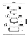
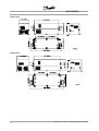
■Dimension diagrams
FramesizeB
FramesizeC
FramesizeD
MG.80.B3.22 - VLT is a registered Danfoss trademark
11

AHF 005/010
FramesizeE
Frame size F
MG.80.B3.22-VLTisaregisteredDanfosstrademark
12

AHF 005/010
Specifications
Frame size G
MG.80.B3.22 - VLT is a registered Danfoss trademark
13

AHF 005/010
■Mechanical installation
The encapsulation of the filters have an I P 20
rating. The modules can be mounted side by side
with 60mm (2,36 inches) clearance.
To other c omponents and to the cabinet walls k eep a
horizontal clearance of at least 70mm (2,76 inches) and
a vertical clearance of at least 150mm (5,91 inches).
Only verti cal installation is allowed (main s
terminal at bottom).
For versions with bus bars (frame size E
– G) i t is necessary to mount the added
covers to the connect ors in order to
achieve th e protection type IP 20.
■Ventilation
The filters are cooled by means of air circulation.
Consequently, the air needs to be able to move freely
above and below the filter module. The efficiency
of the filter modules is greater than 0.98. When
installing a filter module in a panel or another enclosure,
ensure there is sufficient airflow though the enclosure
to limit heat rise in the enclosure.
AHF 0xx
380 – 415V
Max.
Heat
AHF 0xx
440 – 480V
Max.
Heat
AHF 0xx
500V
Max.
Heat
10 A 83 W 10 A 104 W
19 A 158 W 19 A 190 W 19 A 197 W
26 A 216 W 26 A 259 W 26 A 270 W
35 A 290 W 35 A 349 W 35 A 364 W
43 A 358 W 43 A 429 W 43 A 447 W
72 A 599 W 72 A 718 W 72 A 748 W
101 A 840 W 101 A 1008 W 101 A 1050 W
144 A 1197 W 144 A 1437 W 144 A 1496 W
180 A 1496 W 180 A 1796 W 180 A 1871 W
217 A 1804 W 217 A 2165 W 217 A 2255 W
289 A 2403 W 289 A 2883 W 289 A 3003 W
324 A 2694 W 324 A 3232 W 324 A 3367 W
370 A 3076 W 370 A 3691 W
NO
TE
If other he at sources (e.g. Danfoss frequency
converters) are installed in an enclosure
w
ith the harmonic fi lter AHF 0xx, this
heat generation must als o be considered when
calculating required airflow
NO
TE
If the c ool ing air is polluted (dust, d irt swirl,
grease, aggressive gas) the function of
t
he filter module may be impeded. Ensure
sufficient countermeasures, e.g. separate cooling air,
mounting of air filters, periodical cleaning.
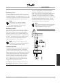
■Power wiring
Standard connection
Supply voltage must be connected to the terminals
X1.1, X1.2 and X1.3. The frequency converter supply
terminals L1, L2 and L3 must be connected to the
filter module terminals X2.1, X2.2 and X2.3.
MG.80.B3.22-VLTisaregisteredDanfosstrademark
14

AHF 005/010
Installation
Paralleling of FC’s
If several frequency converters are to be connected
to the harmonic filter, the connection is similar to the
standard connection - The supply terminals L1, L2 and
L3 of several frequency converters must be conn ected
to the filter module terminals X2.1, X2.2 and X2.3.
NOTE
If several FC’s are to be connected to
the same filter, the harmonic filter must
besizedaccordingtothesumofthe
calculated input current to the FC’s.
Paralleling of filters
If the line input current of the frequency converter
exceeds the nominal current of the largest harmonic
filter, several harmonic filters can be paralle led to
achieve the nece ssary rating. Supply voltage must
be connected to the terminals X1.1, X1.2 and X1.3 of
the filters. The frequency converter supply terminals
L1, L2 and L3 must be connected to the filter
modules terminals X2.1, X2.2 and X2.3.
NOTE
Filters of different current ratings can be
paralleled. The rating of the filter becomes the
sum of the individual current ratings.
Capacitor disconnect
The power factor of the harmonic filter AHF 005/010
is decreasing with decreasing load. At zero load
the Power Factor becomes zero and the capacitors
produce approximately 30% leading current comp
ared
to the rated current of the filter. The reactive current
generated by the filter at partial load is normally
not of any concern, mainly because of the
small
current compared to the system capacity (ma x
30%) as well as the fact that other load normally
compensates the capacitive current.
In applications where this react
ive current may not
be accepted, Terminals X3.1, X3.2, X3.3 and X4.1,
X4, X4.3 are giving acces to the filter capacitors.
As default (on delievery) the wiring will shorten
Terminal X3.1 with X4.1, X3.2 with X4.2 and X3.3 with
X.4.3. In the case of that no capacitor disconnect
is required no changes should be made. If capacitor
disconnecet is required a three-phase contactor should
be placed between terminals X3 and X4. Size the
contactor an d wiring to 50% of the nominal current
and use the AC3 rating of the contactor
NOTE
Only switch the contactor at less than 20% load.
Allow m inimum 5 minutes for the capacitors
to discharge before turning on again.
Use cables complying with local regulations.
MG.80.B3.22 - VLT is a registered Danfoss trademark
15

AHF 005/010
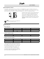
■Over temperature contactor
The Danfoss harmonic filter AHF 005 and AHF 010 is equipped with a galvanic isolated contactor that is
closed under normal operating conditions and open if the filter is overheated. This contactor can be used for
preventing damag es to the filter caused by over temperature as shown in the following exam ple .
Example: Conn ec t term ina l A of the harmonic filter to
terminal 12 or13 (voltage supply digital input, 24V)
of the Danfoss frequency converter and term inal
Btoterminal27(digitalinput"CoastInverse")the
frequency converter will let go of the motor (coasting)
and thereby unload the filter if a over temperature is
detected.
NOTE
The maximum rating of the over temperature
contactor
is 250V AC and 10A.
■Power wiring size
Power wiring size
Enclosure Max. cable size mm
2
Type Nom. Fix Torque
B 16 Connector 2Nm
CandD 50 Connector 6Nm
E, F, G and H Bus Bars 25 Nm
Overheat contactor (copper)
Enclosure Max. cable size mm
2
Type Nom. Fix Torque
4 Connector 0.6 Nm
Capacitor disconnect (copper)
Enclosure Max. cable size mm
2
Type Nom. Fix Torque
B 4 Connector 0.6 Nm
CandD 16 Connector 2Nm
E, F, G and H 50 Connector 6Nm
*Power wiring used for connection of the filter AHF
005 and A HF 010 in enclosure size E, F and G must
be terminated with cable lugs that can be attached
to the input and output bus bars terminals. This
type of term ination imposes no specifications of
the minimum and maximum cable size suitable for
connection. Power terminal details regarding the bus
bars can be found in the figures below.
MG.80.B3.22-VLTisaregisteredDanfosstrademark
16

AHF 005/010
Installation
Frame E
Frame F Frame G, Frame H
NOTE
For UL approval use copper conductor only.
■Operation on different mains type
Mains type Operation of the filter module
TN Directly grounded star point Allowed
TN Indirectly grounded star point Allowed
IT Isolated star point Allowed
The filter module has been designed completely
symmetrically for three phase operation and without
referencetothestarpointorprotectiveearth.
MG.80.B3.22 - VLT is a registered Danfoss trademark
17

AHF 005/010
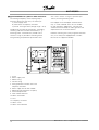
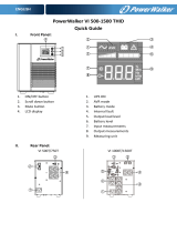
■Typical installation in a panel or other enclosures
To avoid high frequency noise coupling keep a
minimum distance of 150 mm (5.91 inches) to:
a) mains/supply wires
b) motor wires of frequency converter
c) control- and signal wires (voltage range < 48 V)
To obtain low resistive HF-connections, grounding,
screening and other metallic connections (e. g.
mounting plates, mounte d units) should have a
surface as large as possible to metallic ground.
Use grounding and potential equalisation wires
with a cross section as large as possible (min.
10mm²) or thick grounding tape s.
Use copper or tinned copper screened wires
only, as steel screened wires are not suitable
for high frequency applications. Connect the
screen with metal clamps or metal glands to the
equalisation bars or PE-connections.
Inductive switching units (relay, magnetic contactor
etc.) must always be equipped with varistors,
RC-circuits or suppressor diodes.
1. Panel
2. Mains supply wire
3. Motor wiring
4. Control wiring
5. Wiring between harmonic filter and
frequency conv
erter
6. Mains supply wire of filter module
7. Mounting plate (common star point)
8. Potential equali
sation
9. Filter module AHF 0xx
10. Mains c onnection
11. PLC
12. Frequency converter
13. Mains fuses
14. Mains circuit breake
r
MG.80.B3.22-VLTisaregisteredDanfosstrademark
18

AHF 005/010
Commissioning
■Commissioning
Prior to initial switch-on of the f ilter module
check the wiring for co mpleteness,
short-circuit and earth fault.
If the wiring is n ot correct, a non-inten ded
opera tion of controller and/or filter
module is p ossible.
First powering up
1. Switch on mains supply :
- The filter module is ready for operation at once.
2. Check the readiness of the frequency conve rter:
- Proceed in accordance w ith the operating
instructions of the frequency converter.
MG.80.B3.22 - VLT is a registered Danfoss trademark
19

AHF 005/010
■1. General
During operation, filter mo dules unit may have,
according to their type of protection, live, bare,
in some cases also movable or rotating parts
as well as hot surfaces.
Non - authorized removal of required cove r,
inappropriate use, incorrect installation or operation,
creates the risk of severe injury to persons or
damage to material assets.
Further information can be obtained from
the doc umentation.
All operations concerning transport, installation and
commissioning as we ll a s maintenance must be
carried out by qualified, skilled personnel (IEC 364 and
CENELEC HD 384 or DIN VDE 0100 and IEC-Report
664 or DIN VDE 0110 and national regulations for the
preventions of accidents mus t be observed).
According to this basic safety information qualified
skilled personnel are persons who are familiar with
the erection, ass embly, commis sioning and operation
of the product and who have the qualifications
necessary for their occupatio n .
2. Application as directed
Filter modules are components, which are designed
for installation in electrical systems or machinery.
When installing in machines, commissioning of
the filter modules (i.e. the starting of operation as
directed) is prohibited until it is proven, that the
machine corresponds to the regulations of the
EC Directive 83/392/EEC (Machinery Directive);
EN 60204 must be observed.
Commissioning (i.e. starting operation as directed)
is only allowed when there is com p l iance with
the EMC-Directive 89/336/EEC.
The filter modules meet the requirements of the
Low-Voltage Directive 73/23/EEC. The technical data
and information on the connection conditions must be
obtained from the nameplate and the documentation
and m ust be observed in all cases.
3. Transport, Storage
Notes on transport, storage and appropriate
handling must be observed.
The filter modules have to be protected from
inadmissible stress. In particular during transport
and handling no components are allowed to be b end
and / or isolating distances may not be altered.
The units are equipp ed with electrostatic sensitive
devices, which may be damaged by improper handling.
Therefore it has to be avoided to get in contact with
electronic components. If electronic components are
damaged mechanically the unit must not be put into
operation, as it cannot b e ensured, that all relevant
standards are observed. Climatic conditions must
be observed according to prEN 50178.
4. Installation
The devices must be erected and cooled according to
the regulations of the corresponding documentation.
The filter modules must be protected from ina ppropriate
loads. Partic ularly during transport and handling,
components must not be bent and / or isolating
distances mus t not be changed. Touching of electronic
components and contacts must be avoided.
Filter modules contain electro-statically sensitive
components, w hich can easily be damaged b y
inappropriate handling. Electrical components
must not be damaged or destroyed mecha nically
(health risk are possible!).
5. Electrial Installation
When working on l ive filter modules, the valid national
regulations for the prevention of accidents (e.g.
VBG 4) must be observed. Before any installation
or connection works, the plant has to be switched
off and to be secured properly.
The electrical insta llation must be carried out
according to the appropriate regulations (e.g. cable
cross-sections, fuses, PE-connection). More detailed
information is included in the documenta tion. When
using the filte r module with frequency converters
without safe separation from the supply line (to
VDE 0100) all control wiring has to be included in
MG.80.B3.22-VLTisaregisteredDanfosstrademark
20
Page is loading ...
-
 1
1
-
 2
2
-
 3
3
-
 4
4
-
 5
5
-
 6
6
-
 7
7
-
 8
8
-
 9
9
-
 10
10
-
 11
11
-
 12
12
-
 13
13
-
 14
14
-
 15
15
-
 16
16
-
 17
17
-
 18
18
-
 19
19
-
 20
20
-
 21
21


Danfoss VLT® AHF 005/010 Operating Operating instructions
- Type
- Operating instructions
- This manual is also suitable for
Ask a question and I''ll find the answer in the document
Finding information in a document is now easier with AI
Related papers
-
Danfoss VLT® Micro Drive FC 51 DIN Rail Kit Installation guide
-
Danfoss VLT 5000 (Legacy Product) Operating instructions
-
-
-
-
Danfoss VLT® Advanced Harmonic Filter AHF005/010 User guide
-
Danfoss VLT 6000 (Legacy Product) Installation guide
-
Danfoss VLT® AutomationDrive User guide
-
Danfoss VLT® 5000 FLUX SW 5.5x Operating Instructions Manual
-
Other documents
-
 Ranger design 6052 Installation guide
-
 VLT FC 322 Design Manual
-
HP Modular Cooling System Installation guide
-
Hagerco 904S - Vinyl Carpet / Tile Transition Installation guide
-
 RiteTemp 6022 Installation guide
-
 RiteTemp 6022 Installation guide
-
Anybus AB7961 Installation guide
-
 Pass Labs X2.2 User manual
-
-
 PowerWalker VI 750 T-HID IEC UK Owner's manual


