Electro-Voice EVC-1122-95 Installation guide
- Category
- Speaker sets
- Type
- Installation guide
This manual is also suitable for

EVC Compact Front-Loaded Loudspeakers
en | Installation manual


Table of contents
1
Safety 4
1.1 Important safety instructions 4
1.2 Suspension 4
1.3 Precautions 5
1.4 Notices 5
2
Short information 6
3
Introduction 7
4
Installation 9
4.1 Tools list 9
4.2 General aiming and placement guidelines 9
4.3 Preparing the EVC loudspeakers for installation 9
4.3.1 Unpacking and inspection 9
4.3.2 Scope of delivery 9
4.3.3 Recommended pre-installation procedures 9
4.4 Rotation of high-frequency waveguides 10
4.5 Working with mounting accessories 11
4.5.1 Mounting with a U-bracket 12
4.5.2 Mounting with a pivoting wall bracket 13
4.5.3 Suspending an EVC loudspeaker using M10 suspension points 14
5
Rigging strength ratings and safety factors 16
6
Electrical connection 19
6.1 Low impedance connection 19
7
Technical data 21
7.1 EVC-1082-96 8" speaker 90x60 21
7.2 EVC-1082-00 8" speaker 100x100 23
7.3 EVC-1122-64 12" speaker 60x45 25
7.4 EVC-1122-95 12" speaker 90x55 27
7.5 EVC-1152-64 15" speaker 60x45 29
7.6 EVC-1152-95 15" speaker 90x55 31
7.7 EVC-1181S 18" subwoofer 33
8
Accessories (optional) 35
8.1 Installation of TK-150 transformer for passive crossovers 35
8.2 Input panel covers 38
9
References 39
9.1 Rigging (printed) 39
9.2 Mechanical engineering (printed) 39
9.3 Rigging (websites) 39
en 3
Electro-Voice Installation manual 2018.01 | 01 | F.01U.345.998

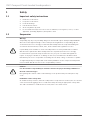
Safety
Important safety instructions
1. Read these instructions.
2. Keep these instructions.
3. Heed all warnings.
4. Follow all instructions.
5. Clean only with a dry cloth.
6. Do not install near any heat sources such as radiators, heat registers, stoves, or other
apparatus (including amplifiers) that produce heat.
Suspension
!
Warning!
Suspending any object is potentially dangerous and should only be attempted by individuals
who have a thorough knowledge of the techniques and regulations of suspending objects
overhead. Electro-Voice strongly recommends that loudspeakers be suspended taking into
account all current national, federal, state, and local laws and regulations. It is the
responsibility of the installer to ensure all loudspeakers are safely installed in accordance
with all such requirements. When loudspeakers are suspended, Electro-Voice strongly
recommends the system be inspected at least once per year or as laws and regulations
require. If any sign of weakness or damage is detected, remedial action should be taken
immediately. The user is responsible for making sure the wall, ceiling, or structure is capable
of supporting all objects suspended overhead. Any hardware used to suspend a loudspeaker
not associated with Electro-Voice is the responsibility of others.
!
Caution!
It is the installer's responsibility to determine and use the proper mounting hardware for
the wall construction type.
Disregarding this caution could result in damage to the product and personal injuries may
occur.
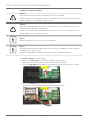
Redundant seismic safety cable
As an added safety measure, when the loudspeaker is suspended or mounted, the user should
connect an unused rigging point to a solid structural point using an appropriate safety cable.
The cable should have a small amount of slack, but no more than ¾ inch.
1
1.1
1.2
EVC Compact Front-Loaded Loudspeakers
2018.01 | 01 | F.01U.345.998 Installation manual Electro-Voice

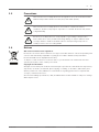
Precautions
!
These Electro-Voice loudspeakers were designed for use in an environment with
ambient temperatures between -20°C (-4°F) and +50°C (122°F).
!
These Electro-Voice loudspeakers are not rated for continuous outdoor
conditions. However, they may be exposed to occasional short-term rain, water,
or high humidity.
!
Electro-Voice loudspeakers are easily capable of generating sound pressure
levels sufficient to cause permanent hearing damage to anyone within normal
coverage distance. Caution should be taken to avoid prolonged exposure to
sound pressure levels exceeding 90 dB.
Notices
Old electrical and electronic appliances
Electrical or electronic devices that are no longer serviceable must be collected separately and
sent for environmentally compatible recycling (in accordance with the European Waste
Electrical and Electronic Equipment Directive).
To dispose of old electrical or electronic devices, you should use the return and collection
systems put in place in the country concerned.
Copyright and disclaimer
All rights reserved. No part of this document may be reproduced or transmitted in any form by
any means, electronic, mechanical, photocopying, recording, or otherwise, without the prior
written permission of the publisher. For information on getting permission for reprints and
excerpts, contact Electro-Voice.
All content including specifications, data, and illustrations in this manual are subject to change
without prior notice.
1.3
1.4
en 5
Electro-Voice Installation manual 2018.01 | 01 | F.01U.345.998

Short information
The following table lists products in a family, with CTN (Commercial Type Number) and
identifying product name DESCRIPTION.
CTN DESCRIPTION
EVC-1082-96B 8" speaker, 90x60 indoor, black
EVC-1082-96W 8" speaker, 90x60 indoor, white
EVC-1082-96PIB 8" speaker, 90x60 weatherized, black
EVC-1082-96PIW 8" speaker, 90x60 weatherized, white
EVC-1082-00B 8" speaker, 100x100 indoor, black
EVC-1082-00W 8" speaker, 100x100 indoor, white
EVC-1082-00PIB 8" speaker, 100x100 weatherized, black
EVC-1082-00PIW 8" speaker, 100x100 weatherized, white
EVC-1122-64B 12" speaker, 60x45 indoor, black
EVC-1122-64W 12" speaker, 60x45 indoor, white
EVC-1122-64PIB 12" speaker, 60x45 weatherized, black
EVC-1122-64PIW 12" speaker, 60x45 weatherized, white
EVC-1122-95B 12" speaker, 90x55 indoor, black
EVC-1122-95W 12" speaker, 90x55 indoor, white
EVC-1122-95PIB 12" speaker, 90x55 weatherized, black
EVC-1122-95PIW 12" speaker, 90x55 weatherized, white
EVC-1152-64B 15" speaker, 60x45 indoor, black
EVC-1152-64W 15" speaker, 60x45 indoor, white
EVC-1152-64PIB 15" speaker, 60x45 weatherized, black
EVC-1152-64PIW 15" speaker, 60x45 weatherized, white
EVC-1152-95B 15" speaker, 90x55 indoor, black
EVC-1152-95W 15" speaker, 90x55 indoor, white
EVC-1152-95PIB 15" speaker, 90x55 weatherized, black
EVC-1152-95PIW 15" speaker, 90x55 weatherized, white
EVC-1181S-B 18" subwoofer indoor, black
EVC-1181S-W 18" subwoofer indoor, white
EVC-1181S-PIB 18" subwoofer weatherized, black
EVC-1181S-PIW 18" subwoofer weatherized, white
2
EVC Compact Front-Loaded Loudspeakers
2018.01 | 01 | F.01U.345.998 Installation manual Electro-Voice

Introduction
EVC loudspeakers from Electro-Voice include five basic models. Three of them are two-way
trapezoidal loudspeaker systems that can be used in a wide variety of applications where wide
bandwidth, vertical and horizontal directivity control, and high efficiency are required in a
compact, cost-effective package. The EVC Variable Intensity model is a two-way design with a
unique compound waveguide that can evenly cover a defined rectangular audience area with
almost no variation in sound quality and minimal change in level. The 18” subwoofer will
complement any of the full-range systems. EVC loudspeakers are voiced so that they can be
seamlessly used in systems with other EV-Innovation models (EVF, EVH, and EVA).
The high frequency section of EVC loudspeakers comprises a single 1¼-inch pure titanium
dome compression driver directly coupled to a rotatable constant directivity waveguide that
delivers uniform pattern control and smooth, linear response. The low frequency section
employs a high-output woofer that was developed using state-of-the-art, computer-aided
optimization to provide low distortion, high efficiency, and maximum intelligibility at high
sound pressure levels. The passive crossover implements an enhanced fourth-order design
with slopes of greater than 24 dB per octave for smooth off-axis response and improved
definition through the critical vocal range. The subwoofer requires an external high-pass filter
or crossover; it is the only model without an internal passive filter network.
The EVC series is an extremely cost effective solution for many fixed-install applications. The
enclosures are constructed of 15-mm plywood and finished with EVCoat for enhanced
durability. The loudspeakers have been designed with multiple M10 rigging points as well as
attachment points for an optional U-bracket or multi mount style pan/tilt wall mount. There
are no bracket options for the subwoofer. All EVC loudspeakers accept wire gauges up to 10
AWG. The input panel also accepts optional covers with NL4-type connectors or weatherized
gland-nuts.
For 70V/100V operation, the input panel has an internal landing pad for mounting EV's high-
quality TK-150 audio transformer. When the transformer is installed, it engages EV's patented
Automatic Saturation Compensation (ASC), which preserves low frequency performance while
presenting a stable load to the amplifier - regardless of the number of speakers connected in
parallel. As a result, EVC loudspeakers - including the subwoofers - sound virtually identical,
whether they are used with a transformer or without.
Numbering scheme
The numbering scheme for EVC models is similar to that of other EV-Innovation loudspeakers.
It denotes the number and diameter of the woofers, the number of passbands, the coverage
pattern, level of weatherization, and the enclosure color. EVC speakers are available in black
or white and in your choice of robust EVCoat and partially weatherized versions. For example,
the EVC-1082-96PIW employs a single eight-inch woofer in a two-way configuration with a 90°
x 60° waveguide coverage pattern, and has a white, weatherized enclosure. Similarly, the
EVC-1181S-B uses a single 18” woofer to cover a single passband. In other words, it is a
subwoofer or low-frequency system in a black enclosure.
Finishes and colors available
EVC loudspeakers are finished in tough EVCoat. In addition, PI versions are rated for indirect
outdoor exposure in protected areas, such as under a roof overhang, and feature a stainless-
steel grille backed with acoustically-transparent hydrophobic cloth and a water-tight dual-
3
en 7
Electro-Voice Installation manual 2018.01 | 01 | F.01U.345.998

gland-nut input-panel cover. External fasteners on PI systems are stainless steel. All EVC
systems are available in black or white. Black is indicated by B at the very end of the model
number and white is indicated by W.
To find current user documentation visit our product related information at
www.electrovoice.com.
See also
• Technical data, page 21
EVC Compact Front-Loaded Loudspeakers
2018.01 | 01 | F.01U.345.998 Installation manual Electro-Voice

Installation
Tools list
The tools required to prepare the system for installation are:
▪ 3/16-inch (5 mm) flat blade screwdriver
▪ 6 mm Allen wrench
▪ Phillips #2 screwdriver
General aiming and placement guidelines
Loudspeakers should be pointed at the people and away from reflective room surfaces. Since
people are excellent absorbers of sound and room surfaces are often not, this practice
ensures not only that the audience will perceive the high frequencies necessary for good voice
and musical clarity, but also that acoustic reflections do not excessively degrade intelligibility.
Loudspeakers for sound reinforcement are usually located above a stage or platform and
aimed down and out into the audience. This minimizes the difference between the longest
throws to the rear of a venue and the shortest throws to the front rows, promoting uniform
coverage. Note that a typical portable loudspeaker on a short, 6-foot stand cannot duplicate
such uniformity since the distant seats are so much farther away than the front rows. The
direct sound from a loudspeaker drops 6 dB every time the distance from it doubles,
according to the formula:
Level loss (dB) = 20log
10
(closest distance/farthest distance).
Preparing the EVC loudspeakers for installation
Unpacking and inspection
Carefully open the packaging and take out the loudspeaker. Inspect the loudspeaker's
enclosure for any damage that might have happened during transportation. Each loudspeaker
is examined and tested in detail before leaving the manufacturing site. Please inform the
transport company immediately if the loudspeaker shows any damage. Being the addressee,
you are the only person who can claim damages in transit. Keep the cardboard box and all
packaging materials for inspection by the transport company.
Keeping the cardboard box including all packing materials is also recommended, even if the
loudspeaker shows no external damage.
When shipping the loudspeaker, make sure to always use its original box and packaging
materials. By packing the loudspeaker exactly as it was packed by the manufacturer, you will
guarantee optimum protection from transport damage.
Scope of delivery
Keep the original invoice that states the purchase/delivery date in a safe place.
Recommended pre-installation procedures
For any sound system, certain checks made at the installer’s place of business can prevent
expensive on-site delays. EV recommends that you take the following steps:
1. Unpack all loudspeakers in the shop.
2. Check for proper model numbers.
3. Check the overall condition of the loudspeakers.
4. Check for continuity at the loudspeaker inputs.
4
4.1
4.2
4.3
4.3.1
4.3.2
4.3.3
en 9
Electro-Voice Installation manual 2018.01 | 01 | F.01U.345.998

Once you are on site and the loudspeakers are connected, it is a good idea to check again for
continuity at the power-amplifier end of each cable run.
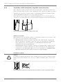
Rotation of high-frequency waveguides
EV loudspeakers are shipped with the wider waveguide pattern angle in the horizontal
orientation when the speaker is upright. If desired, the waveguide can be rotated so that the
wider pattern angle is in the vertical orientation. All high-frequency waveguides are labeled
with their horizontal and vertical coverage angles, so you can easily identify the current
orientation.
Tools required:
▪ Phillips #2 screwdriver
To rotate the high-frequency waveguide, do the following:
1. Remove the three screws on each side of the grille.
2. Pop the grille out.
3. Remove the eight screws holding the compression-driver/waveguide assembly.
4. Rotate the waveguide assembly 90°.
4.4
EVC Compact Front-Loaded Loudspeakers
2018.01 | 01 | F.01U.345.998 Installation manual Electro-Voice

5. Reinstall the waveguide assembly.
6. Reinstall the grille.
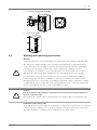
Working with mounting accessories
!
Warning!
Suspending any object is potentially dangerous and should only be attempted by individuals
who have a thorough knowledge of the techniques and regulations of suspending objects
overhead. Electro-Voice strongly recommends that loudspeakers be suspended taking into
account all current national, federal, state, and local laws and regulations. It is the
responsibility of the installer to ensure all loudspeakers are safely installed in accordance
with all such requirements. When loudspeakers are suspended, Electro-Voice strongly
recommends the system be inspected at least once per year or as laws and regulations
require. If any sign of weakness or damage is detected, remedial action should be taken
immediately. The user is responsible for making sure the wall, ceiling, or structure is capable
of supporting all objects suspended overhead. Any hardware used to suspend a loudspeaker
not associated with Electro-Voice is the responsibility of others.
!
Caution!
It is the installer's responsibility to determine and use the proper mounting hardware for
the wall construction type.
Disregarding this caution could result in damage to the product and personal injuries may
occur.
Redundant seismic safety cable
As an added safety measure, when the loudspeaker is suspended or mounted, the user should
connect an unused rigging point to a solid structural point using an appropriate safety cable.
The cable should have a small amount of slack, but no more than ¾ inch.
4.5
en 11
Electro-Voice Installation manual 2018.01 | 01 | F.01U.345.998

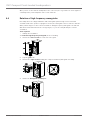
Mounting with a U-bracket
There are two U-Bracket models (EVC-UB1 and EVC-UB2) for mounting EVC full-range
loudspeakers on a wall or ceiling.
Figure 4.1: EVC U-bracket installed vertically or horizontally
EVC U-Bracket
EVC loudspeaker models
EVC-UB1 is an optional U-Bracket kit for
mounting a single EVC-1082 system to a wall
or ceiling.
Available in black or white:
▪ EVC-UB1-BLK
▪ EVC-UB1-WHT
The EVC-UB1 fits EVC-1082 models:
EVC-1082-96B
EVC-1082-96W
EVC-1082-96PIB
EVC-1082-96PIW
EVC-1082-00B
EVC-1082-00W
EVC-1082-00PIB
EVC-1082-00PIW
EVC-UB2 is an optional U Bracket kit for
mounting a single EVC-1122 or EVC-1152
system to a wall or ceiling.
Available in black or white:
▪ EVC-UB2-BLK
▪ EVC-UB2-WHT
The EVC-UB2 fits all trapezoid-shaped
EVC-1122 and EVC-1152 models:
EVC-1122-64B
EVC-1122-64W
EVC-1122-64PIB
EVC-1122-64PIW
EVC-1122-95B
EVC-1122-95W
EVC-1122-95PIB
EVC-1122-95PIW
EVC-1152-64B
EVC-1152-64W
EVC-1152-64PIB
EVC-1152-64PIW
EVC-1152-95B
EVC-1152-95W
EVC-1152-95PIB
EVC-1152-95PIW
Table 4.1: EVC U-Bracket mounting models
For more information, see EVC-UB1 and EVC-UB2 Adjustable U-Mount Mounting Bracket
Installation Instructions (F.01U.349.929).
4.5.1
EVC Compact Front-Loaded Loudspeakers
2018.01 | 01 | F.01U.345.998 Installation manual Electro-Voice

Mounting with a pivoting wall bracket
The most flexible mounting accessory for EVC loudspeakers is the wall bracket, which can be
adjusted for a wide range of pan/tilt positioning angles. With the wall bracket, you will be able
to achieve more precise aiming than is possible with the U-Bracket. The wall bracket will fit
any of the trapezoidal loudspeakers; there is no wall bracket for the VI or subwoofer models.
Figure 4.2: EVC-WB multi mount wall bracket
EVC multi mount wall bracket
EVC loudspeaker models
The EVC-WB is a pan/tilt Omnimount-style
wall mount bracket for mounting EVC-1082,
EVC-1122, or EVC-1152 loudspeakers.
Available in black or white:
EVC-WB-BLK
EVC-WB-WHT
EVC-1082-96B
EVC-1082-96W
EVC-1082-96PIB
EVC-1082-96PIW
EVC-1082-00B
EVC-1082-00W
EVC-1082-00PIB
EVC-1082-00PIW
EVC-1122-64B
EVC-1122-64W
EVC-1122-64PIB
EVC-1122-64PIW
EVC-1122-95B
EVC-1122-95W
EVC-1122-95PIB
EVC-1122-95PIW
EVC-1152-64B
EVC-1152-64W
EVC-1152-64PIB
EVC-1152-64PIW
EVC-1152-95B
EVC-1152-95W
EVC-1152-95PIB
EVC-1152-95PIW
Table 4.2: EVC Multi Mount Wall Mount Bracket mounting models
For more information, see EVC-WB Multi Mount Wall Mount Bracket Installation Instructions
(F.01U.349.932).
4.5.2
en 13
Electro-Voice Installation manual 2018.01 | 01 | F.01U.345.998

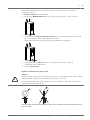
Suspending an EVC loudspeaker using M10 suspension points
EVC loudspeakers must be hung in an inverted orientation when suspended from the insert
points. The trapezoidal enclosures require attachment to three points. The subwoofer requires
attachment at four points. It is not possible to suspend EVC speakers horizontally. A safety
cable should always be attached to one of the suspension points.
EVC loudspeakers are designed to be installed individually. There are no factory-approved
accessories for creating clusters by connecting an EVC loudspeaker to any other loudspeaker.
Figure 4.3: Suspending EVC systems, including a safety cable
Eyebolt accessory kits
EVC loudspeakers do not ship with eyebolts. To suspend the speaker, it is necessary to order
one of the accessory eyebolt kits (sold separately).
▪ EBK-M10-3PACK: optional eyebolt kit, consisting of three M10 shoulder eyebolts and
three fender washers, used when eyebolts are needed to suspend any of the full-range
EVC loudspeakers. For more information see, EBK-M10 Eyebolt Attachment Kit
Installation Instructions (F.01U.303.870).
▪ EBK-M10-4PACK: optional eyebolt kit, consisting of four M10 shoulder eyebolts and four
fender washers, used when eyebolts are needed to suspend any of the full-range EVC
loudspeakers or the EVC-1181S subwoofer. For more information see, EBM-M10-4PACK
M10 Eyebolt Attachment Kit Installation Instructions (F.01U.349.930).
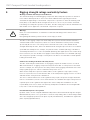
Installing the eyebolts
!
Caution!
No eyebolt should be mounted in the sides of an EVC enclosure in order to suspend a system.
Doing so may result in damage to the enclosure, leading to installation failure, and personal
injury.
Figure 4.4: Eyebolts installed incorrectly in the sides of an enclosure in order to suspend it from above
4.5.3
EVC Compact Front-Loaded Loudspeakers
2018.01 | 01 | F.01U.345.998 Installation manual Electro-Voice

All hardware supplied by the user must be rated for overhead lifting to suspend the
loudspeaker system.
To install the eyebolts, do the following:
1. Remove the M10 flat-head bolts from the fly points you will use on the enclosure.
2. Screw the lifting eyebolt with fender washer into the threaded attachment point until
the fender washer makes contact with the enclosure.
Never install the eyebolt without the washer included with the eyebolt kit.
3. Finger tighten the eyebolt until the correct alignment position is obtained.
A maximum of one complete turn.
4. Install a safety cable.
Eyebolts orientated in the plane of pull
!
Caution!
Eyebolts must be fully seated and oriented in the plane of pull. Always use the fender washer
included with the eyebolt kit to distribute the load on the enclosure.
Excessive tightening of the eyebolt with a wrench, screwdriver or other tool, can result in a
system failure and possible injury.
Figure 4.5: Fully seated eyebolts with washers, with correct orientation in the plane of pull (Correct; left,
Incorrect; right)
en 15
Electro-Voice Installation manual 2018.01 | 01 | F.01U.345.998

Rigging strength ratings and safety factors
Working load limit and safety-factor definitions
The structural ratings for all EVC rigging components and loudspeaker systems are based on
test results in which parts were stressed to failure. Manufacturers typically present the
structural-strength ratings of mechanical components or systems as either the Working Load
Limit (WLL) or the ultimate-break strength. Electro-Voice chooses to present the structural-
load ratings of loudspeaker systems as the WLL. The WLL rating represents the maximum load
that should ever be applied to a mechanical component or system.
!
Warning!
Never exceed the limitations or maximum recommended working load for Electro-Voice
loudspeakers.
Disregarding this warning could result in serious injury or death.
The WLL for the rigging components and loudspeaker systems described in this manual is
calculated with a 10:1 safety factor, which exceeds the minimum 8:1 safety factor normally
specified by Electro-Voice. The safety factor is defined as the ratio of the ultimate-break
strength divided by the WLL, where the ultimate-break strength represents the force at which
a part will structurally fail. For example, if a part has a WLL of 100 lb (45.4 kg), it would not
structurally fail until a force of at least 1,000 lb (453.6 kg) was applied, based on a 10:1 safety
factor. However, the user should never apply a load to that part that exceeds 100 lb (45.4 kg).
The safety factor provides a margin of safety above the WLL to accommodate normal dynamic
loading and normal wear.
Cautions for working load limits and safety factors
The WLL defined by the manufacturer of any rigging component should never be exceeded.
Other manufacturers of rigging components may base their WLL on safety factors other than
10:1. For example, 5:1 safety factors are fairly common among rigging manufacturers because
many regulatory agencies call for a minimum safety factor of 5:1.
When an EV loudspeaker system is installed where local regulations only require a safety
factor of 5:1, Electro-Voice insists that the WLL of the loudspeaker rigging never be exceeded
and that an 10:1 safety factor be maintained.
The user is cautioned that some local regulations may require safety factors higher than 10:1.
In those circumstances, Electro-Voice insists that the user maintain the higher safety factor as
required by the local regulations throughout the entire loudspeaker installation. It is the
responsibility of the user to make sure that any loudspeaker installation meets all applicable
local, state or federal safety regulations.
Recommended practice for eyebolts
Eyebolts can be used to suspend individual loudspeakers when attached through the integral
M10 attachment points. It is a good idea to orient the suspending cable so that it hangs within
30° of the straight-up position in the plane of pull (left illustration), and within 15° against the
plane of pull (right illustration).
5
EVC Compact Front-Loaded Loudspeakers
2018.01 | 01 | F.01U.345.998 Installation manual Electro-Voice

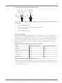
Suspension line angle limits for individual eyebolts
0°
30°
90°
30°
90°
0°
15°
15°
A
B
C
D
A
B
Figure 5.1: Suspension line angle limits for individual eyebolts, both in plane of pull (left) and against plane
of pull (right)
A
Above 90° NOT TO BE USED
B 0° to 30° recommended for main suspension line angle
C ±15° for all applications
D Above 15° NOT TO BE USED
Suspension line angles
Refer to Working load limit for M10 eyebolts and EVC loudspeakers, page 17 and Suspension
line angle limits for individual eyebolts, page 17 for specific eyebolt angle and weight limitations
when using eyebolt suspension. These limits are not to be exceeded under any circumstances.
If a safety factor higher than 10:1 is required, the angle limits for each eyebolt may actually
decrease to a number less than what is shown in Suspension line angle limits for individual
eyebolts, page 17.
Working load limit for M10 eyebolts and EVC loudspeakers
Model
WLL Each Point (10:1) WLL Each Speaker (10:1)
EVC-1082 30 lb 30 lb
EVC-1122-64 or EVC-1122-95 55 lb 55 lb
EVC-1122-VI 55 lb 55 lb
EVC-1152 65 lb 65 lb
EVC-1181S 85 lb 85 lb
Table 5.1: WLL for M10 eyebolts and EVC loudspeakers
Always ensure that the suspension line is in the plane of the eyebolt, as shown in Eyebolts
orientated in the plane of pull, page 15. Readjust the eyebolt during the installation if necessary
to maintain this alignment.
en 17
Electro-Voice Installation manual 2018.01 | 01 | F.01U.345.998

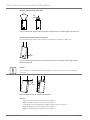
Eyebolt suspension-line angle limit
60º
MAX
60º
MAX
Figure 5.2: All-eyebolt suspension-line angle limit, independent (left) or bridled (right) suspension lines
Left-to-right all-eyebolt suspension angles
The suspended all-eyebolt cluster must be perpendicular (plumb) to within ±5°.
5º
MAX
Figure 5.3: Left-to-right angle limits for an all-eyebolt suspension (visual angle shown exaggerated for
illustration purposes)
Notice!
The PI models need a minimum 10° downward tilt to minimize risk of water entering the
enclosure.
10º TILT
Figure 5.4: EVC PI models 10° minimum downward tilt
See also
• Rigging strength ratings and safety factors, page 16
• Rigging strength ratings and safety factors, page 17
• Suspending an EVC loudspeaker using M10 suspension points, page 15
• Rigging strength ratings and safety factors, page 18
• Rigging strength ratings and safety factors, page 17
EVC Compact Front-Loaded Loudspeakers
2018.01 | 01 | F.01U.345.998 Installation manual Electro-Voice

Electrical connection
Low impedance connection
All EVC full-range systems are passive, meaning that the internal crossover/equalizer network
sends low frequencies to the woofer and high frequencies to the compression-driver/
waveguide combination. In addition, the network tailors the frequency response and level of
each individual driver so that the overall frequency response of the loudspeaker is essentially
flat over its intended range of operation. There is no bi-amp option for EVC full-range
loudspeakers.
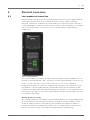
Figure 6.1: EVC input panel
The screw terminals on the input panel will accept wire gauges as large as AWG 10. There are
two pairs of terminals labeled + and -. A speaker-level audio signal should be connected to one
of these +/- pairs. The other +/- pair can be used to connect one or more additional
loudspeakers in parallel, as long as the combined load impedance does not drop too low for
the amplifier to operate reliably. When the TK-150 audio transformer is installed in an EVC
loudspeaker, the ASC feature will automatically keep the impedance of each loudspeaker in a
safe range. The two pairs of connections marked THRU are wired as pass-through connections
for a separate audio signal.
Optional speaker processing
Once an EVC loudspeaker is installed in a venue a Digital Signal Processor (DSP) will typically
be used to adjust the in-room frequency response. In addition, the DSP should be used to
provide the high-pass filters recommended to protect EVC systems against overdrive at
frequencies below their operating range. Failure to do so could damage the low-frequency
drivers if the system is subjected to high-level signals below its operating range.
6
6.1
en 19
Electro-Voice Installation manual 2018.01 | 01 | F.01U.345.998

Models Recommended high-pass frequency (minimum)
EVC-1082 50 Hz, 4
th
-order high-pass (24dB/octave)
EVC-1122 45 Hz, 4
th
-order high-pass (24dB/octave)
EVC-1152 40 Hz, 4
th
-order high-pass (24dB/octave)
EVC-1181S 35 Hz, 4
th
-order high-pass (24dB/octave)
Table 6.1: Recommended high-pass filter frequencies for infrasonic protection of EVC systems
The recommended high-pass filter can be implemented in a stand-alone DSP loudspeaker
controller or in the processing section of a DSP-enabled amplifier. L Series and C Series
amplifiers from Dynacord are recommended for use with EVC loudspeakers because they can
also implement model-specific processing that optimizes loudspeaker performance. EVC
loudspeaker settings can also be implemented in any IRIS-Net compatible digital signal
processor.
EVC Compact Front-Loaded Loudspeakers
2018.01 | 01 | F.01U.345.998 Installation manual Electro-Voice
Page is loading ...
Page is loading ...
Page is loading ...
Page is loading ...
Page is loading ...
Page is loading ...
Page is loading ...
Page is loading ...
Page is loading ...
Page is loading ...
Page is loading ...
Page is loading ...
Page is loading ...
Page is loading ...
Page is loading ...
Page is loading ...
Page is loading ...
Page is loading ...
Page is loading ...
Page is loading ...
-
 1
1
-
 2
2
-
 3
3
-
 4
4
-
 5
5
-
 6
6
-
 7
7
-
 8
8
-
 9
9
-
 10
10
-
 11
11
-
 12
12
-
 13
13
-
 14
14
-
 15
15
-
 16
16
-
 17
17
-
 18
18
-
 19
19
-
 20
20
-
 21
21
-
 22
22
-
 23
23
-
 24
24
-
 25
25
-
 26
26
-
 27
27
-
 28
28
-
 29
29
-
 30
30
-
 31
31
-
 32
32
-
 33
33
-
 34
34
-
 35
35
-
 36
36
-
 37
37
-
 38
38
-
 39
39
-
 40
40


Electro-Voice EVC-1122-95 Installation guide
- Category
- Speaker sets
- Type
- Installation guide
- This manual is also suitable for
Ask a question and I''ll find the answer in the document
Finding information in a document is now easier with AI
Related papers
-
Electro-Voice EVC-VI EN54 Installation guide
-
Electro-Voice TK-150 Installation guide
-
-
Electro-Voice EBK1 User manual
-
-
-
-
-
-
Electro-Voice Electro-Voice EVERSE8US Weatherized Battery Powered Loudspeaker User manual
Other documents
-
König KNM-SM10 Datasheet
-
Pure Acoustics PX 408 User manual
-
Biamp WX-1200 Owner's manual
-
Optimus SC-630 /EU Datasheet
-
 Taga Harmony Commercial Audio TBS Series User manual
-
-
 TW Audio M10 Operating instructions
-
 Adaptive Technologies Group MM-016-BT Installation guide
-
EAW EAW Owner's manual
-
Samson UB1 User manual


