Page is loading ...

Texmate, Inc. Tel. (760) 598-9899 • www.texmate.comTM-35 Data Sheet (T7) Page 1
General Features Specifications
Typical Application Connections
TM-35 Series LED Displays TM-35 Series LCD Displays
TM-35JC
TM-35KC
TM-35JF
TM-35KF
Panel Temperature Meters
Texmate’s popular TM-35 Series of 5V DC powered tempera-
ture meters are available with an LED or LCD display.
The meters are supplied factory-configured either for ‘J’ or ‘K’
thermocouples, and scaled for ˚C or ˚F. On site re-scaling for ˚C
or ˚F is possible. A selectable ˚C/˚F descriptor is included with
every meter. The unique differential input configuration facili-
tates operation with both grounded and ungrounded probes and
allows several meters, operating with grounded thermocouples,
to be powered by the same non-isolated 5VDC supply.
Input Configuration: ......... True differential and single ended
Thermocouple Ranges: .....0 to 760˚C
0 to 1400˚F
0 to 1260˚C
0 to 1999˚F
(consult factory for other types)
Resistance Effect: ............20µV per 10Ω of lead resistance.
Compensation (RJC): ....... Automatic, ±0.1˚C/˚C.
Input Protection: ............... 25V AC/DC.
Normal Mode Rejection: .. >40dB above 50Hz.
Common Mode Rejection: >90dB (inputs shorted).
Common Mode Voltage: ... ±4V referred to power supply ground.
Conformity Error: .............±(2˚C + 1 Count) typical
±(4˚C + 1 Count) maximum
±(3˚F + 1 Count) typical
±(5˚F + 1 Count) maximum
Resolution: ........................ 1˚C or 1˚F
Warm-up Time: ..................One minute to specified accuracy
Conversion Rate: .............. 3 readings per second
Display: .............................. 0.56" high efficiency LED "Display Hold" &
˚C/˚F descriptor
Over-range Indication: ..... Most Significant "1" digit and polarity
symbol are displayed with all other digits
blank.
Power Supply: ................... +4.75 to +5.25V DC at 225mA
Operating Temperature: ... 0˚C to +50˚C
Storage Temperature:....... -20˚C to +70˚C
Relative Humidity: ............ 95% (non-condensing)
Case Dimensions: ............Bezel 2.76” X 1.17” (69.75 X 29.7mm)
Depth behind Bezel 3.32” (84mm) plus
0.68” (17.27mm) for connector
Weight: ............................... 156 gms (5.5 oz) when packed
'J' Thermocouple
'K' Thermocouple
TM-35JC ............3.5 digit LED-Type J °C Thermocouple, 5VDC Pwr
TM-35JF ............3.5 digit LED-Type J °F Thermocouple, 5VDC Pwr
TM-35KC ...........3.5 digit LED-Type K °C Thermocouple, 5VDC Pwr
TM-35KF..............3.5 digit LED-Type K °F Thermocouple, 5VDC Pwr
TM-35XJC ..........3.5 digit LCD-Type J °C Thermocouple, 5VDC Pwr
TM-35XJF ..........3.5 digit LCD-Type J °F Thermocouple, 5VDC Pwr
TM-35XKC ..........3.5 digit LCD-Type K °C Thermocouple, 5VDC Pwr
TM-35XKF ...........3.5 digit LCD-Type K °F Thermocouple, 5VDC Pwr
Meter 1 Meter 2 Meter 3
Hot Junction 1 Hot Junction 2 Hot Junction 3
H/T
T+
T-
+5V
GND
5VDC
H/T
T+
T-
+5V
GND
H/T
T+
T-
+5V
GND
Vessel Wall
The unique dif-
ferential input of
the TM-35 Series
enables the use of
grounded thermo-
couples by several
meters powered from
the same 5V DC
supply.
Single-Ended Input
Zero Offset
Span
Linearity
TM-35
GND
+5V
T-
T+
H/T
5V DC
Differential Input with Grounded Thermocouples
For additional connection information see page 3.
For optimum noise
rejection, either the +
or - lead of the ther-
mocouple should be
connected to power
supply ground.
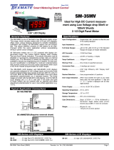
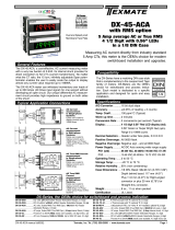
A low cost LED temperature meter for 'J' or 'K' thermocouples,
˚C or ˚F, 5V DC powered with screw terminal or edge connector inputs.
TM-Series
3 1/2 Digit 0.56” LED

Texmate, Inc. Tel. (760) 598-9899 • www.texmate.comPage 2 TM-35 Data Sheet (T7)
ZERO OFFSET
SPAN
LINEARITY
R16
R31 R24 R28 R14 R9 R27
Calib. Pt. 'A' (R25)
R7 C8 R29
R26
R4
R32
R30
C5
R8
R6
C4
R22
C6
R23
VR1C13
R18
C12
R1A
C11
R1B
R20
R17
R19
R10
R15
The Texmate TM-35 interconnects using the screw terminal blocks
supplied with the meter. Alternatively a standard PC board edge con-
nector may be used, having two rows of 10 pins each, spaced on 0.156"
centers. Connectors are available from Texmate or from almost any
connector manufacturer.
Pins (A,B) & (1,2) - Display Test/Display Hold Input: All numeric
display segments will operate when Pins (A,B) & (1,2) are connected to
+5VDC System Power Input Pins (H,J) & (7,8). The function of this input
may be re-configured to operate as Display Hold by scraping off the fine
track adjacent to Pin 1 (re-bridge, if required, at solder junctions). To
initiate Display Hold in this configuration, connect Pins (A,B) & (1,2) to
+5VDC Power Supply Input Pins (H,J) & (7,8) and the meter will latch
up; A/D conversions will continue but the display will not be updated
until Pins (A,B) & (1,2) are released.
Pins (C,D) & (3,4) - Thermocouple Positive Input: The thermocouple
positive output is applied to these pins (refer to Table 2 for color codes).
Maximum overvoltage protection is 25V AC/DC.
Pins (E,F) & (5,6) - Thermocouple Negative Input: The thermocouple
negative output is applied to these pins (refer to Table 2 for color codes).
Maximum overvoltage protection is 25V AC/DC.
Pins (H,J) & (7,8) - +5VDC System Power Input: The meter requires a
regulated low-ripple 5VDC power supply applied to these pins.
Pins (K,L) & (9,10) - Power Supply Ground: Power supply ground
return.
H/T H/T
T+ T+
T- T-
+5V +5V
GND
GND
1
2
3
4
5
6
7
8
9
A
B
C
D
E
F
H
J
K
L
123 4 5 6 78 9
ABC D E F HJ K L
10
10
METER REAR WITH PCB EDGE CONNECTOR MOUNTED
Display Test/
Hold Input
Thermocouple
Positive Input
Thermocouple
Negative Input
+5VDC System
Power Input
Power Supply
Ground
Display Hold/
Test Input
Thermocouple
Positive Input
Thermocouple
Negative Input
+5VDC System
Power Input
Power Supply
Ground
Fine "Scrape Off" Tracks Solder Junction
Zero Offset Span Linearity
COMPONENT SIDE PINS SOLDER SIDE PINS
Ω
C13
0.1 μ
R7, 100k C8, 100pF
Ω
ZERO
OFFSET
R14
2.49k Ω
R9
2.49k
Ω
SPAN
Ω
BUFFER
C12
+5V
T-
0.1μ
C5,
R4
1M
F
0.2 Fμ
C6,
1μF
C4
+1.2V Ref.
R10
Ω
R6, 270k Ω
R1A, 309
R1B, 309
Ω
Ω
R18
R19
R20
VR1
1.2V
R15
2k
-10mV/˚K RJC Sensor
Ω
Ω
0.1μF
R23
R22
R32 R31 R29 R28
R27
R26
R30 R24
R25 R17
200
R16
619
(Bias and power supply connections
have been omitted for clarity)
LINEARIZATION CIRCUITRY - 'J' TYPE
(Dashed lines represent connections for 'K' type)
CLOCK OSCILLATOR OPEN HOLD
CLOSED TEST
+5V
Power
Power
GND
H/T
T+
C11
0.22 μF
+1.2V Ref.
LINEARITY
CALIB. PT. 'A'
Close For
Hold/Test
Activation
C
INTEGRATOR
COMPARATOR
A/D CONVERTER
DC/DC CONVERTER
50k
F
R8
40.2k ΩR34
470 Ω
'J' Thermocouple Shown Below
Additional Components for 'K' Shown Shaded
Functional Diagram
Connector Pinouts
Component Layout
POINTS TO NOTE
The TM-35 has been factory calibrated for optimum performance and
should not normally require further calibration or adjustment.
If the need for on-site re-calibration is determined, follow the procedure
below and verify that the voltage and meter display are incorrect before
disturbing potentiometer settings.
Note: The potentiometer settings are sealed at the factory. Any
user modification of these settings may, at the discretion of
Texmate, void the warranty.
Re-calibration requires either a thermocouple simulator or a precision
millivolt source, thermocouple reference junction, and an ice point ref-
erence. A digital voltmeter is also required. The calibration arrangement
used should completely simulate normal thermocouple connections to
the meter. The drawing below illustrates the connection details when
using a millivolt source and an ice point reference.
Calibration Instructions
GND
+5V
T-
T+
H/T
5V DC
THERMOCOUPLE
WIRES
COPPER
WIRES
MILLIVOLT
SOURCE
DISTILLED ICE WATER BATH
OR
ELECTRONIC ICE POINT REFERENCE
Signal Conditioning Components
ZERO Potentiometer (Pot)
The ZERO pot is on the left (as viewed from the
back of the meter). Typically it enables the input
signal to be offset ±5% of full scale.
SPAN Potentiometer (Pot)
The 15 turn SPAN pot is middle pot (as viewed
from the back of the meter). Typical adjustment is
20% of the input signal range.
Use to set voltage at
Calibration Point "
A"
To the
Right Front
LINEARITY
LINEARITY Potentiometer (Pot)
The Linearity pot is used to set the voltage at
the calibration Point “A” and is located on the
right (as viewed from the back of the meter).
The Linearity Pot is adjusted at the factory and
does not normally need to be re-adjusted by
the user.
CAUTION: This meter employs high impedance CMOS inputs. Although internal
protection has been provided for several hundred volt overloads, the meter will
be destroyed if subjected to the high kilovolts of static discharge that can be
produced in low humidity environments. Always handle the meter with ground protection.
Cut to disable “+” polarity indication

Texmate, Inc. Tel. (760) 598-9899 • www.texmate.comTM-35 Data Sheet (T7) Page 3
The TM-35 may be configured for
single-ended operation by con-
necting the thermocouple positive
or negative input to power supply
ground. This configuration is rec-
ommended for operation using an
ungrounded (isolated) thermocou-
ple.
Note: This circuit is also suitable for
use with a grounded thermocouple,
provided that the supply powering
the meter is isolated with respect
to ground. In this case, a separate
5V supply should be used for each
meter, or the meter should be used
in a differential configuration.
The differential input feature of the TM-35 facilitates tempera-
ture measurement using grounded thermocouples. In this con-
figuration, an indirect ground return path is still required to pre-
vent the common mode range of the inputs from being exceed-
ed, but the circuit differs from the single-ended configuration in
that the power supply ground is connected to the thermocouple
junction common point, rather than to the thermocouple posi-
tive or negative input on the meter. This avoids the introduction
of circulating currents in the thermocouple wires arising from
ground loops, which may otherwise result in erroneous or noisy
readings. Several meters may be cascaded in this configuration
all powered by the same 5VDC supply, as shown above.
GND
+5V
T-
T+
H/T
5V DC
Meter 1 Meter 2 Meter 3
Hot Junction 1 Hot Junction 2 Hot Junction 3
H/T
T+
T-
+5V
GND
5VDC
H/T
T+
T-
+5V
GND
H/T
T+
T-
+5V
GND
Vessel Wall
'J'
'K'
Positive
Negative
Negative
Positive
BRITAIN
BS 1843
FRANCE
NF C42-323 GERMANY
DIN 43714
U.S.A.
ANSI/
MC964
JAPAN
JIS C 1610-
1981
Yellow Yellow
Yellow Yellow
Red
Black
Brown
Blue
Purple GreenBlue
Blue
Red
Red
Red
Red
Red
White
White
White
Yellow
Sheath
Blue
Sheath
GB FDUSA JPN
Thermocouple Color Codes
Single-Ended Meter
Differential-Input Meter
Calibration Instructions Continued
Before calibration, determine the values for linearity, zero offset, and
span adjustment from the table. As an example, the values appropriate
for a TM-35JC ('J' thermocouple, °C scaling) are: 760° (linearity), 0°
(zero offset), and 760° (span). Having determined these values, follow
the steps described below:
NOTE: For re-scaling between ˚C/˚F, linearity re-calibrated (Step1)
may be omitted.
1. Calibrate the LINEARITY
Apply the linearity calibration voltage to the TM-35. Connect the voltme-
ter to calibration point 'A' (shown on the component layout). Adjust the
LINEARITY potentiometer (R17) until the voltage at point 'A' is exactly
1.000V.
2. Calibrate the ZERO OFFSET
Apply the zero offset calibration voltage to the TM-35 . Adjust the zero
offset potentiometer (R15) to make the meter display zero. The optimal
setting is achieved when the polarity sign alternates between '+' and '-'.
3. Check the calibration
Apply the span calibration voltage to the TM-35. Adjust the span poten-
tiometer (R10) until the meter display matches the value shown in table
one.
4. Selection of the °C/°F Descriptor
Refer to the "Descriptor Re-Selection" procedure on page 4. This
should only be necessary if the meter is re-scaled between °C and °F.
CALIBRATION
Separate potentiometers are provided for adjustment of linearity, zero
offset, and span. Calibration involves the application of various voltag-
es representing temperatures according to the thermocouple type and
meter scaling. These values are summarized in the table below in terms
of temperature and equivalent thermocouple voltage output.
'J' Type 'K' Type
C F
760
42.922mV
0
0.000mV
760
42.922mV
1400
42.922mV
0
-0.885mV
1400
42.922mV
1260
50.990mV
0
0.000mV
1260
50.990mV
1990
44.645mV
0
-0.701mV
1990
44.645mV
T/C Simulator
Millivolt Source
Linearity (R17)
Calib. Pt.'A' = 1.000V
Zero Offset (R15)
Zero Adjustment
Span (R10)
Full Scale Adjustment
T/C Simulator
T/C Simulator
Millivolt Source
Millivolt Source
C F
˚˚˚ ˚
CAUTION - ELECTRICAL SHOCK HAZARD All internal parts of the meter may
be at the same electrical potential as the input signal and power supply. A suitable
high voltage warning notice should be affixed to those meters where there is any
possibility that the meter could be removed from its case, or the internal com-
ponents accessed, concurrent with the existence of a high voltage input signal.
A removable folded film insert is
supplied with legends for ˚C and
˚F scalings. The sharp tip of the
insert fits between the LED and the
black heat-shrink band that encases
the LED. It’s orientation is factory
selected for ˚C or ˚F illumination as
appropriate.
If the meter is recalibrated on-site to a different scaling, remove
the meter from the case. Invert the folded film insert with fingers
or tweezers so that the ˚C or ˚F descriptor legend aligns with
the square descriptor LED and insert the sharp tip of the insert
between the black heat-shrink band and the LED.
˚F
˚C
INVERT
˚C/˚F Descriptor Re-Selection

Texmate, Inc. Tel. (760) 598-9899 • www.texmate.comPage 4 TM-35 Data Sheet (T7)
Ordering Information
TM Case Dimensions and Panel Cutouts
Special Options and Accessories
Part Number Description
ACCESSORIES
CN-L10 ....... Edge Connector with Solder eyelet, 10 Pin Dual
TB-KIT.......... Terminal Block Connector Kit (3)
Case Dimensions
TOP VIEW
FRONT VIEW
PANEL CUTOUT SIDE VIEW
16.82mm
0.662in
29.60mm
1.165in
14.50mm
0.571in
64.77mm
2.550 in
24.64mm
0.970in
69.90mm
2.752in
option metal
screw mounting clip
102.36mm
4.030in
84.50mm
3.330in
Edge connector
When extra panel mounting
tightness is required, optional
Screw Mounting Clips can be
purchased seperately and attach
to the sliding mounting side clips
8.50mm
0.335in
2.50mm
0.098in
WARRANTY
Texmate warrants that its products are free from defects in material and workmanship under
normal use and service for a period of one year from date of shipment. Texmate’s obligations
under this warranty are limited to replacement or repair, at its option, at its factory, of any of
the products which shall, within the applicable period after shipment, be returned to Texmate’s
facility, transportation charges pre-paid, and which are, after examination, disclosed to the sat-
isfaction of Texmate to be thus defective. The warranty shall not apply to any equipment which
shall have been repaired or altered, except by Texmate, or which shall have been subjected
to misuse, negligence, or accident. In no case shall Texmate’s liability exceed the original pur-
chase price. The aforementioned provisions do not extend the original warranty period of any
product which has been either repaired or replaced by Texmate.
USER’S RESPONSIBILITY
We are pleased to offer suggestions on the use of our various products either by way of printed
matter or through direct contact with our sales/application engineering staff. However, since
we have no control over the use of our products once they are shipped, NO WARRANTY
WHETHER OF MERCHANTABILITY, FITNESS FOR PURPOSE, OR OTHERWISE is made
beyond the repair, replacement, or refund of purchase price at the sole discretion of Texmate.
Users shall determine the suitability of the proDXct for the intended application before using,
and the users assume all risk and liability whatsoever in connection therewith, regardless
of any of our suggestions or statements as to application or construction. In no event shall
Texmate’s liability, in law or otherwise, be in excess of the purchase price of the product.
Texmate cannot assume responsibility for any circuitry described. No circuit patent or software
licenses are implied. Texmate reserves the right to change circuitry, operating software, speci-
fications, and prices without notice at any time.
TM-35 Technical Manual Copyright © 2020 Texmate Inc. All rights reserved.
Published by: Texmate Inc. USA. Information in this Technical Manual is
subject to change without notice due to correction or enhancement. The
information described in this manual is proprietary to Texmate, Inc. and may
not be copied, reproduced or transmitted, in whole or in part, in connection
with the design, manufacture, or sale of apparatus, device or private label
product without the express written consent of Texmate, Inc.
1934 Kellogg Ave., Carlsbad, CA 92008
Tel: 1-760-598-9899 • 1-800-TEXMATE
Fax: 1-760-598-9828 • Email: [email protected]
Standard Options for this Model Number
Part Number Description
BASIC MODEL NUMBER
TM-35JC ................ 3.5 digit LED-Type J °C Thermocouple, 5VDC Pwr
TM-35JF ................ 3.5 digit LED-Type J °F Thermocouple, 5VDC Pwr
TM-35KC ............... 3.5 digit LED-Type K °C Thermocouple, 5VDC Pwr
TM-35KF ................ 3.5 digit LED-Type K °F Thermocouple, 5VDC Pwr
TB-Kit Screw Connectors
Texmate’s individual screw ter mi nal blocks offer a convenient
al ter na tive to edge connectors for many ap pli ca tions, allowing
com plete in stal la tion, con figu ra tion and calibration with out the
need for soldering.
Slide each terminal block over the PCB until the hole aligns.
Insert the re tain ing screw to secure.
Each kit includes: 3 plastic blocks with metal contacts, 4 screws
with spade connectors, 1 metal contact and 3 quick disconnects.
*Not Included
PCB Edge Connector
A standard 20-pin edge con nec tor (two rows of 10 pins on
0.156" centers) is used to connect all TM-35 meters.
Order part no. CN-L10.
PCB Edge Connector
/

