Page is loading ...

2150 joshua's Path, Suite 302, Hauppauge, NY 11788
Phone : 1-800-645-5398 or 1-639-231-7050
Fax : 1-639-434-3128 • E-mail : [email protected]
www.awsperry.com
92-1536A
11/05 Form #273
OPERATING
INSTRUCTION
MODEL 4105
Disital Earth Resistance Tester

1. Safty Precautions
The instrument is designed, manufactured, tested and shipped in prime
condition in accordance with the following standards.
IEC 61010-1 Measurement CAT III 300V Pollution Degree 2
IEC 61010-2-31
IEC 61557-1,5
IEC 60529 (IP54)
This instruction manual contains warnings and safety rules which must be
observed by the user to ensure safety operation of the instrument and to
retain it in safe condition. Therefore, read through these instructions before
using the instrument.
WARNING
Read through and understand instructions contained in this manual
before using the instrument.
Save and keep the manual handy to enable quick reference whenever
necessary.
Be sure to use the instrument only in its intended applications and to
follow measurement procedures described in the manual.
Be sure to understand and follow all safety instructions contained in the
manual.
Be sure to observe the above rules strictly. Not following the instructions
may cause injury or instrument damage.
The symbol on the instrument means that the user must refer to the
manual for safe operation of the instrument. There are three kinds of the
symbol . Read the instructions following each symbol carefully.
---- 1 ----
CONTENTS
1. Safety Precautions …………………………………………………………… 1
2. Features ………………………………………………………………………… 4
3. Specifications…………………………………………………………………… 5
4. Layout Diagram ………………………………………………………………… 8
5. Preparation for Measurement ………………………………………………… 9
5-1 Battery Voltage Check …………………………………………………… 9
5-2 Connecting Test Probes ………………………………………………… 9
6. Operating Instructions ………………………………………………………… 9
6-1 Principle of Measurement ……………………………………………… 9
6-2 Precise Measurement …………………………………………………… 10
6-3 Simplified Measurement ………………………………………………… 11
7. Battery Replacement ………………………………………………………… 14
8. Notes on Housing Case & Accessories …………………………………… 15
8-1 Case Lid…………………………………………………………………… 15
8-2 How to Fit Strap Belt …………………………………………………… 15
9. Before Sending for Service ………………………………………………… 16
10. Service ……………………………………………………………………… 17

DANGER is reserved for conditions and actions that are likely to cause
serious or fatal injury.
WARNING is reserved for conditions and actions that can cause
serious or fatal injury.
CAUTION is reserved for conditions and actions that can cause minor
injury or instrument damage.
DANGER
Make sure that the range selector switch is set to a desired position
before making measurement.
Do not make measurement in the presence of flammable gasses.
Otherwise, the use of the instrument may cause sparkling, which leads
to an explosion.
Never attempt to connect the test probe if the instrument or your hand is
wet.
Do not apply an electrical quantity exceeding the allowable limit of a
measuring range.
Never open the battery compartment cover while making measurement.
WARNING
Never attempt to make measurement, if any abnormal conditions are
noted, such as broken case, cracked test probe and exposed metal
parts.
Never turn the range selector switch with test probe connected to the
equipment under test.
Do not install substitute parts or make any decomposition or
modification to the instrument. Return the instrument to A.W. SPERRY
or your distributor for repair or re-calibration.
Do not replace batteries when the surface of the instrument is wet.
Always set the range switch to the OFF position before opening the
battery compartment cover for battery replacement.
CAUTION
Make sure that the test probe are securely connected to the terminal of
the instrument.
Be sure to set the range selector switch to the OFF position after use.
When the instrument will not be in use for a long period of time, place it
in storage after removing the batteries.
Do not expose the instrument to the direct sun, extreme temperature
and humidity or dew fall.
Use a damp cloth soaked in water or neutral detergent for cleaning the
instrument. Do not use abrasives or solvents.
When the instrument is wet, make sure to let it dry before putting it in
storage.
---- 3 -------- 2 ----

3. Specifications
Measuring Range and Accuracy (at 23 5°C and RH 75% or less)
Range
Measuring Range
Accuracy
Earth Voltage 0 - 199.9V 1.0% rdg 4 dgt
20Ω0 - 19.99Ω2.0% rdg 0.1Ω( 0 - 19.99Ω)
Earth 2.0% rdg 3 dgt( above 20Ω)
Resistance 200Ω0 - 199.9Ω
(Auxiliary earth resistance 100Ω5%)
2000Ω0 - 1999Ω(Earth voltage 10V or less)
Electromagnetic compatibility(Radiated RF immunity & IEC61000-4-3)
RF field strength = ≤1V/m, total accuracy : specified accuracy
RF field strength = 3V/m, total accuracy :
specified accuracy +5% of
range
Applicable Standards
IEC 61010-1 Measurement CAT III 300V Pollution Degree 2
IEC 61010-2-31
IEC 61557-1,5
IEC 60529 (IP54)
Measuring Method
Earth voltage measurement
Average sensing
Earth resistance measurement
Constant current inverter
Frequency : Approx. 820Hz
Measuring current : 20Ωrange Approx. AC 3mA
---- 5 ----
2. Features
MODEL 4105 is an earth resistance tester for testing power distribution lines,
in-house wiring system, electrical appliances etc. It also has an earth voltage
range for earth voltage measurement.
Designed to safety standard IEC 61557.
Dust and drip proof construction in conformity with IEC 60529 (IP54).
Measurement can be made even under adverse weather conditions.
Large, easy-to-read LCD digital display.
Simplified measurement probe has a structure that both the alligator clip
and the test bar are available.
Warns when earth resistance of auxiliary earth spikes exceeds the
permissible limit.
Convenient carrying soft bag for accessories etc.
---- 4 ----

Power Source
9V DC : R6P (SUM-3) x6
Overload Protection
Earth resistance ranges : 280V AC/DC (10 seconds)
Earth voltage range : 300V AC/DC (1 minute)
Insulation Resistance
5MΩor more at 500V between the electrical circuit and the housing case
Withstand Voltage
3700V AC for one minute between the electrical circuit and the housing
case
Dimensions
105(L) x 158(W) x 70(D) mm
Weight
Approx. 550g
Accessories
M-7095 Test Leads x 1 set
M-8032 Auxiliary Earth Spikes x 2
M-7127 Simplified Measurement Probe x 1 set
(with safety alligator clip and flat test bar)
M-9084 Carrying Case x 1
Strap Belt x 1
Instruction Manual x 1
Battery R6P (SUM-3) x 6
---- 7 ----
Maximum Operating Error
Operating error (B) is an error obtained within the rated operating
conditions, and calculated with the intrinsic error (A), which is an error of
the instrument used, and the error (Ei) due to variations.
A:Intrinsic error
E1:Variation due to changing the position
E2:Variation due to changing the supply voltage
E3:Variation due to changing the temperature
E4:Variation due to series interference voltage
E5:Variation due to resistance of the probes and auxiliary earth
electrode resistance
E7:Variation due to changing the system frequency
E8:Variation due to changing the system voltage
Range to keep the maximum operating error
Measurement range within which the maximum operating error ( 30%)
applies.
20Ωrange : 5-19.99Ω
200Ωrange : 20-199.9Ω
2000Ωrange : 200-1999Ω
Number of Measurement
3300 times or more
( Measure 10Ωfor 5s on 20Ωrange and take a pause for 25s)
Operating Temperature and Humidity
0 - 40°C, relative humidity 85% or less (no condensation)
Storage Temperature and Humidity
-20 - 60°C, relative humidity 75% or less (no condensation)
---- 6 ----

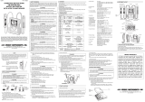
4. Layout Diagram
qLCD Display wBattery Replacement Mark
eIndication LED With qq(Low Battery Symbol)
qqMeasurement(Green) rPress To Test Button
tRange Selector Switch yMeasuring Terminals
uTest Leads iAuxiliary Earth Spikes
oSimplified Measurement Probe !0 Safety Alligator Clip
!1 Test Bar
---- 8 ----
5. Preparation for Measurement
5-1 Battery Voltage Check
Turn on the instrument. If the display is clear without low battery symbol
"" showing, battery voltage is sufficient. If the display blanks or " " is
indicated, replace the batteries according to section 7 for Battery
Replacement.
5-2 Connecting Test Probe
Insert the plug of the probe securely into the terminals of the instrument.
Loose connection may result in inaccurate measurements.
6.Operating Instructions
DANGER
The instrument will produce a maximum voltage of about 50V between
terminals E-C in earth resistance function. Take enough caution to
avoid electric shock hazard.
When measuring earth voltage, do not apply voltage greater than 200V
between measuring terminals.
When measuring earth resistance, do not apply voltage between
measuring terminals.
6-1 Principle of Measurement
This instrument makes earth resistance measurement with fall-of-
potential method, which is a method to obtain earth resistance value Rx
by applying AC constant current
I between the measurement
object E (earth electrode) and C
(current electrode), and finding
out the potential difference V
between E and P (potential
electrode).
Rx = V / I
---- 9 ----

---- 10 ----
20Ωwhen the earth resistance is low. This indicated value is the earth
resistance of the earthed equipment under test.
Note : If the auxiliary earth resistance of auxiliary earth spike C is too
high to make measurement, the display reads '...'. Recheck the
connection of test leads and the earth resistance of auxiliary earth
spike.
CAUTION
If measurement is made with the probes twisted or in touch with each
other, the reading of the instrument may be affected by induction. When
connecting the probes, make sure that they are separated.
If earth resistance of auxiliary earth spikes is too large, it may result in
inaccurate measurement. Make sure to stick the auxiliary earth spike P
and C into the moist part of the earth carefully, and ensure sufficient
connections between the respective connections.
6-3 Simplified Measurement (with Test Probe M-7127)
Use this method when the auxiliary earth spike cannot be stuck. In this
method, an existing earth electrode with a low earth resistance, such as
a metal water pipe, a common earth of a commercial power supply and
an earth terminal of a building, can be used with two-terminal method
(E,P).
Use the simplified measurement probe attached which has a convenient
structure that both the safety alligator clip and the test bar are available.
qWiring
Make connection as shown in the figure.
---- 11 ----
6-2 Precise Measurement (with Test Probe M-7095)
qTest probe connection
Stick the auxiliary earth spikes P and C into the ground deeply. They
should be aligned at an interval of 5-10m from the earthed equipment
under test. Connect the green wire to the earthed equipment under
test, the yellow wire to the auxiliary earth spike P and the red wire to
the auxiliary earth spike C from terminals E, P and C of the instrument
in order.
Note : Make sure to stick the auxiliary earth spikes in the moist part of the
soil. Give enough water where the spikes have to be stuck into the
dry, stony or sandy part of the earth so that it may become moist.
In case of concrete, lay the auxiliary earth spike down and water it,
or put a wet dustcloth etc. on the spike when making measurement.
wEarth Voltage Measurement
Set the range switch to EARTH VOLTAGE position in the condition of
q. Earth voltage will be indicated on the display. Make sure that the
voltage is 10V or less.
When the display reads more than 10V, it may result in excessive
errors in earth resistance measurement. To avoid this, make
measurement after reducing the voltage by turning off the power
supply of the equipment under test etc.
ePrecise Measurement
Set the range switch to 2000Ωposition and press the test button. LED
remains illuminated during testing. Turn the range switch to 200Ωand

wEarth Voltage Measurement
Set the range switch to EARTH VOLTAGE position in the condition of
q. Earth voltage will be indicated on the display. Make sure that the
voltage is 10V or less.
When the display reads more than 10V, it may result in excessive
errors in earth resistance measurement. To avoid this, make
measurement after reducing the voltage by turning off the power
supply of the equipment under test etc.
eSimplified Measurement
Set the range switch to 2000Ωposition and press the test button. LED
remains illuminated during testing. Turn the range switch to 200Ωand
20Ωwhen the earth resistance is low. This indicated value is the earth
resistance of the earthed equipment under test.
Note : If the auxiliary earth resistance of auxiliary earth spike C is too
high to make measurement, the display reads '...'. Recheck the
connection of each test lead and the earth resistance of auxiliary
earth spike.
rSimplified Measurement Value
Two-terminal method is used for simplified measurement. In this
method, earth resistance value re of earth electrode connected to
terminal P is added to true earth resistance value Rx and shown as
an indicated value Re.
Re = Rx + re
If the re is known beforehand, true earth resistance value Rx is
calculated as follows.
Rx = Re --- re
---- 13 ----
Note : When the simplified measurement probes are not used, short P
and C terminals.
DANGER
Please be sure to use a voltage detector to check a common earth of
commercial power supply.
Do not use the instrument to check a common earth of commercial
power supply.
A danger will be caused because the voltage may not be displayed
even in case of a live conductor when the connection of the earth
electrode to be measured has come off, or when the connection of the
test leads of the instrument is not correct etc.
Do not use the instrument to measure the voltage of commercial power
supply.
The instrument is not designed for voltage measurement of commercial
power supply. When using the adjunctive simplified measurement
probe MODEL 7127, P and C terminals will be short-circuited and the
input impedance will be reduced. The residual current circuit breaker
may operate when making measurement of the voltage in the circuit
with the breaker.
---- 12 ----

---- 15 ----
7. Battery Replacement
DANGER
Never attempt to open the battery compartment cover, if the outer
surface of the instrument is wet.
Never attempt to replace batteries while making measurement. To avoid
shock hazard, turn the instrument off and disconnect the test leads and
the probes from the instrument before opening the battery compartment
cover.
CAUTION
Do not mix new and old batteries.
Install batteries in the orientation as shown inside the battery
compartment, observing correct polarity.
qTurn off the instrument and disconnect the test probes from the
terminals.
wLoosen two screws on the bottom of the instrument and remove the
battery cover.
eAlways replace all six batteries in correct polarity.
Battery : R6P (AA dry battery) x6
rPut the cover back in place and tighten the two screws.
---- 14 ----
8. Notes on Housing Case & Accessories
8-1 Case Lid
Case lid can be fit under the housing case while making measurement.
8-2 How to Fit Strap Belt
The instrument is equipped with a strap belt to suspend from the neck to
allow both hands to be used freely for easy and safe operation

---- 17 ----
9. Before Sending for Service
If this instrument should fail to operate correctly, return it to your nearest
distributor stating the exact nature of the fault. Before returning the
instrument follow the trouble-shooting guide shown below.
If the instrument does not turn on;
Check whether batteries are missing or they are installed incorrect
polarity. Note that batteries were not installed in the instrument at the time
of shipment.
If the display reads '1...' in earth voltage measurement;
A voltage exceeding 200V is being applied to the instrument.
Halt the measurement immediately, otherwise the instrument may be
damaged.
If the display reads '...' in normal earth resistance measurement;
Stick the auxiliary earth spikes deeper into the earth, or stick them at other
locations; or
Add moisture to the part of the earth where C auxiliary earth spike is stuck
( connected with the red wire ); and
Short the three test leads and check if the display indicates a value near
' 0.00 '. (See section 6 for details.)
If the display reads '...' in simplified earth resistance measurement;
Check if the connection to a metal water pipe, a common earth of
commercial power supply, etc., is secure; or
Use another metal water pipe, common earth of commercial power
supply, etc.
---- 16 ----
10. Service
If this instrument should fail to operate correctly, return to your nearest
distributors stating the exact nature of the fault.

---- 18 ----
Lifetime Limited Warranty
The attention to detail of this fine snap-around instrument is further
enhanced by the application of A.W. Sperry's unmatched service and
concern for detail and reliability. These A.W. Sperry snap-arounds are
internationally accepted by craftsmen and servicemen for their unmatched
performance. All A.W. Sperry's snap-around instruments are
unconditionally warranted against defects in material and workmanship
under normal conditions of use and
service; our obligation under this warranty being limited to repairing or
replacing free of charge, at A.W. Sperry snap-around instrument that
malfunctions under normal operating conditions at rated use.1
Replacement procedure
Securely wrap the instrument and its accessories in a box or mailing bag
and ship prepaid to the address below. Be sure to include your name and
address, as well the name of the distributor, with a copy of your invoice
from whom the unit was purchased, clearly identifying the model number
and date of purchase.
A.W.SPERRY INSTRUMENTS INC.
ATT: Customer service dept.
2150 Joshua's Path, Suite 302,
Hauppauge, NY 11788
1The warranty is not applicable if the instrument has been: misused, abused,
subjected to loads in excess of specifications, has had unauthorized repair or has
been improperly assembled or used.
* Note: Recommended calibration interval should not exceed one year. Calibration
service charges are not covered terms and conditions of warranty.
/