
INSTRUCTIONS INSTRUCCIONES
Conforms to
Cumple con las Normas:
ASTM F1004
Compuerta de seguridad
Security Gate
LIBERTY
L854
L919
L1961
L1962
L867
L920
L1963
L1964
Item numbers
may also end in BB.
Los numeros de los productos
puedenacabarse con las letras BB.
CONJUNTOS
KITS
L768
L769
L773
L774
L775
L776
L777
L1992
L2105
IMPORTANT! READ AND FOLLOW
THESE INSTRUCTIONS
CAREFULLY AND KEEP FOR FUTURE REFERENCE
If you sell or give away this product,
make sure you give this instruction to the new owner.
¡IMPORTANTE! LEA Y SIGA CUIDADOSAMENTE
ESTAS INSTRUCCIONES Y GUÁRDELAS
PARA REFERENCIA FUTURA.
Si vende o regala este producto, asegúrese de darle estas instrucciones
al nuevo dueño.
Children have died or been seriously injured when
gates are not securely installed.
• ALWAYS install and use gates as directed using
all required parts.
• You MUST install wall cups, with screws, to keep the
gate in place. Without wall cups, child can push out and
escape.
• STOP using when child can climb over or dislodge/open
the gate.
• Use only with the locking mechanism securely engaged.
• NEVER use to keep child away from pool.
Niños han muerto o se han lesionado gravemente
cuando las compuertas de seguridad no están
instaladas correctamente.
• SIEMPRE instale y use las compuertas como se indica
usando todas las piezas requeridas.
• DEBE instalar las copas de pared con tornillos para
mantener la puerta de seguridad en su lugar. Sin las
copas de pared, el niño puede empujar la puerta de
seguridad y escapar.
• DEJE DE usar cuando el niño puede escalar o
desalojar/abrir la compuerta.
• Use solamente con el mecanismo de cierre enganchada
correctamente.
• NUNCA use una compuerta de seguridad para
mantener al niño alejado de la piscina.
• This product will not necessarily prevent all accidents.
NEVER leave child unattended.
• Intended for use with children from 6 months through 24 months.
• This safety gate has a manual close system.
• Do not use the safety gate if any components are damaged or missing.
• Ensure the surface you mount gate to is suitable for purpose and
structurally sound such as solid timber, brick or masonry.
• For plaster/gyprock surface, locate the timber beam or stud behind
and mount in this location (mounting on plaster/gyprock alone is not
strong enough and not safe). Do not mount to glass.
• DO NOT install this gate to hollow walls.
• This gate is intended for indoor use and is not to be exposed to
outdoor elements.
• Install this gate away from heaters and other sources of heat.
• Este producto no necesariamente prevenir todos los accidentes.
NUNCA deje al niño desatendido.
• Destinado para el uso con niños de 6 meses a 24 meses.
• Esta compuerta de seguridad es de uso manual.
• No use la compuerta de seguridad si algún componente falta o está
dañado.
• Asegúrese que la superficie a la que se fije la compuerta seguridad
deben ser adecuadas para ese fin y deben ser sólidas
estructuralmente, como madera maciza, ladrillo o albañilería.
• Para superficies de gyprock/yeso, encuentre la viga de madera detrás
y ajuste en esta ubicación (ubicarlo solamente en yeso/gyprock no es
suficientemente fuerte y es inseguro). No ubicar en vidrio.
• NO INSTALE esta barrera en paredes huecas.
• Esta compuerta está destinada a uso en interiores y no se la debe
exponer a los elementos al aire libre.
• Instale la compuerta de seguridad alejada de estufas u otras fuentes
de calor.
WARNING ADVERTENCIA
CAUTION:
With any pressure mounted gate, a construction bar is required across the base. Note, this
bar can be a tripping hazard. If you choose to position a pressure mounted gate at the top of
stairs, use extra caution to step over this bar to prevent trips and falls.
Can be used in conjunction with a Dreambaby® Watch-the-Step®
Gate Ramp (L837) to help avoid tripping.
PRECAUCIÓN:
Como parte del diseño de la compuerta montada a presión,
hay una barra de construcción en la base de la abertura de la compuerta. Para evitar tropezarse o
caerse, tenga especial precaución de pasar por sobre esta barra de construcción de la base de la
compuerta, especialmente se ésta se encuentra ubicada en lo alto de una escalera.
Se puede usar conjuntamente con una rampa para barrera de Watch-the-Step® (L837)
de Dreambaby® para evitar tropezarse.
For customers in US only:
Do Not Return to Store, if you have any
questions, please call us on
336-454-5716,
Toll free: 1-888-271-6959 or email us at
Solo para clientes en los EE. UU .:
No devuelva a la tienda, si tiene cualquier
pregunta por favour llamenos a
(336) 454 5716.
Llamada gratuita: (888) 271-6959 o envíenos
un correo electrónico a info@tee-zed.com
1

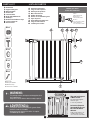
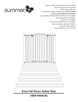
PARTS LIST
WARNING:
The gap in this gate
is NOT a fault.
The gap will disappear
when the gate
is correctly installed
.
La brecha (espacio
intermedio) en esta
barrera NO ES un
defecto.
La brecha desaparecerá
cuando la barrera esté
correctamente instalada.
NOTICE TO CUSTOMERS
GAP •BRECHA
IMPORTANT NOTICE
to Customers
The gap in this gate is NOT a fault.
The gap will disappear when the
gate is correctly installed.
Refer to enclosed instructions for
correct installation procedures.
F - Gate Notice
A
Gate Panel
B
Upper Locking Set
C
Release Switch
D
Gate Frame
E
Tension Knobs
F
Bolts with Rubber Pads
G
Wall Cups
H
Double-sided Adhesive Tape
I
Lower Locking Set
J
Wood Screws
This package contains small parts and sharp points in an
unassembled state.
Keep out of reach of children. Adult assembly required.
ADV
ERTENCIA:
Este paquete contiene piezas pequeñas y puntas filudas
cuando en estado sin ensamblar.
Mantenga fuera del alcance de los niños. Se requiere
ensamblado por un adulto.
AVISO IMPORTANTE A LOS CLIENTES
EN: Wood use only
ES: Úselos solo en madera
Wood Screws
Tornillos para madera
Before you start
Antes de comenzar
Timber =
5/64in (2mm) drill bit
Brick/masonry =
7/32in (5.5mm) drill bit
Madera =
broca de taladro de 5/64in
Ladrillo/albañiler ía =
broca de taladro de 7/32in
LISTA DE PARTES
A
Panel de la Compuerta
B
Juego de cierre superior
C
Interruptor de apertura
D
Marco de la barrera
E
Perillas de tensión
F
Pernos con acolchado de goma
G
Copas de pared
H
Cinta adhesiva de doble cara
I
Juego de cierre inferior
J
Tornillos para madera
G
x 4
J
x 4
H
x 4
E
x 4
F
x 4
C
A
G
H
I
D
BEF
2

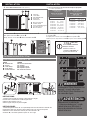
INSTALLATION
Ensure the surface you are mount the gate is structurally sound such as
solid timber, brick or masonry.
For plaster / gyprock surface, locate the timber beam or stud behind and
mount in this location (mounting on plaster / gyprock alone is not strong
enough and not safe). DO NOT MOUNT TO GLASS.
Asegúrese que la superficie sobre la que ubica la barrera es estruc-
turalmente sólida, tal como madera maciza, ladrillos o mampostería.
Para superficies de gyprock/yeso, encuentre la viga de madera detrás
y ajuste en esta ubicación (ubicarlo solamente en yeso/gyprock no es
suficientemente fuerte y es inseguro).
NO UBICAR EN VIDRIO.
1.
Measure the width of the opening of where you intend to install the gate.
For wider openings select the appropriate Gate Extension(s),
sold separately.
1.
Mida el ancho de la abertura donde piensa instalar la barrera.
Para aberturas de más anchas, seleccione el extensor(es), de compuerta apropiado.
INSTALACIÓN
L854 / L919
29.5 - 33in / 75 - 84cm 39 - 42in / 99 - 107cm
L867 / L920
Xtra-Wide
Extra Ancha 29.5 - 33in / 75 - 84cm
L1961 / L1962
Xtra-Tall
Extra Alta
39 - 42in / 99 - 107cm
L1963 / L1964
Xtra-Wide, Xtra-Tall
Extra Ancha, Extra Alta
L768
L769
L773
L774
L775
L776
L777
L1992
L2105
L1961 + L1965 (3.5in/9cm)
L1961 + 2 x L1965 (3.5in/9cm)
L1963 + L1965 (3.5in/9cm)
L1963 + L1965 (3.5in/9cm) + L1967 (7in/18cm)
L854 + 2 x L901 (3.5in/9cm)
L854 + L901 (3.5in/9cm)
L867 + L901 (3.5in/9cm)
L919 + L968 (3.5in/9cm)
L1961 + L1965 (3.5in/9cm) + L1967 (7in/18cm)
75-93cm
75-99cm
99.5-117cm
99.5-135cm
75-99cm
75-93cm
99.5-117cm
75-93cm
75-111cm
29.5-36.5in
29.5-39.5in
39.25-46in
39.25-53in
29.5-39.5in
29.5-36.5in
39.25-46in
29.5-36.5in
29.5-43.5in
Fits openings Ajusta en abertura de
KITS CONJUNTOS
K2
K2
K1
K1
K1
K1
K1
K1
K1
K1
K1
K1
K1
&
&
&
&
&
&
&
&
&
&
&
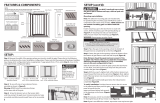
For use on stairs Para su uso en escaleras.
Bottom of stairs
Pie de la escalera
Landing
Descansillo
Top of stairs
Parte de arriba de la escalera
2in
5cm
If the safety barrier is used at the top of stairs, it should not be
positioned below the top level.At the top of landing, position the
gate 2in / 5cm away from the top step.
Si la barrera de seguridad
se usa en la parte
superior de las escaleras,
no debe colocarse
debajo del nivel superior.
En la parte superior del
descanso, coloque la
puerta a 5 cm del
peldaño superior.
If the safety barrier is used at the bottom of the
stairs, it should be positioned at the front of the
lowest tread possible.
Si la barrera de
seguridad se usa en la
parte inferior de las
escaleras, debe
colocarse en la parte
delantera del peldaño
más bajo.
Always
open door
AWAY from
stairs.
Debe abrirla
siempre en
sentido
CONTRARIO a la
escalera.
Floor
Piso
3

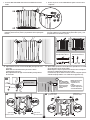
INSTALLATION
3.5in / 9cm
2.
To use with Gate Extensions
sold separately.
WARNING
ADVERTENCIA:
D
Marco de la compuerta
E
Perillas de tensión
F
Pernos y almohadillas de goma
K
Perno de la extensión
L
Marco de extensión
D
Gate Frame
E
Tension Knobs
F
Bolts with Rubber Pads
K
Extension Pin
L
Gate Extension
*L1965/F1966 - 3.5in (9cm)
L1969/F1970 - 10.5in (27cm)
L1971/F1972 - 14in (36cm)
L1973/F1974 - 17.5in (45cm)
L1975/F1976 - 21in (54cm)
L1977/F1978 - 24.5in (63cm)
L1979/F1980 - 39in (100cm)
Xtra-Tall Gate Extensions
(sold separately)
*L901/F968 - 3.5in (9cm)
*L1989 - 3.5in (2x9cm)
L902/F969 - 7in (18cm)
L903/F970 - 10.5in (27cm )
L1951/F1952 - 14in (36cm )
L1953/F1954 - 17.5in (45cm )
L1955/F1956 - 21in (54cm)
L1957/F1958 - 24.5in (63cm)
L1959/F1960 - 39in (100cm)
Gate Extensions
(sold separately)
Marcos de extensión
(se venden separadamente)
Marcos de extensión
Extra alta
(se venden separadamente)
2. Para uso con marcos de extensión de compuerta apropiado
.
se venden separadamente
Insert LONG END of EXTENSION
PIN (K) into Gate Frame
3.5in / 9cm
Introduzca en el marco de
compuerta el “LADO LARGO” de
los pernos de la extensión (K)
INSTRUCTIONS:
1. Install Lower Clamp X onto bottom of gate extension using Z.
2. Insert short end of Extension Pin K into gate frame.
3. Slip the gate extension over pin.
4. Screw Upper clamp Y into place using W.
INSTRUCCIONES
1. Instale el sujetador inferior “X” en la parte debajo del marco de extensión utilizando “Z”.
2. Introduzca “lado corto” del perno de la extension “K” en el marco de compuerta.
3. Deslice el marco de extensión sobre el perno de la extensión “K”.
4. Usando “W”, atornille el sujetador superior “Y” en su lugar.
PARTS
K
- Extension Pin
W
- Screws
X
- Lower Clamp
Y
- Upper Clamp
Z
- Connector Screw
PARTES
K
– Perno de la extensión
W
– Tornillos
X
– Sujetador inferior
Y
– Sujetador superior
Z
– Tornillo del conector
KYW
XZ
XZ
Y
W
K
K
X
For Extensions over 3.5in / 27cm
Para Extensores de más de 27 cm
INSTALACIÓN
DL
K
K1
K2
K3
3.5in / 9cm
7in /18cm &
10.5in / 27cm
14in / 36cm —
39in / 100cm
DL
F
K
E
E
F
D
KL
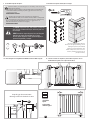
Insert Extension Pins K into the holes on the outside of the Gate Frame D.
Next, slip Extension Frames L over the Pins K.
Finally, slide in the Tension Knobs E and Bolts with Rubber Pads F.
Introduzca los pasadores de extensión K dentro de los hoyos del exterior del marco
de la compuerta D.
En seguida, deslice los marcos de extensión L sobre los pasadores K.
Finalmente, deslice las perillas de tensión E y los pernos con acolchado de goma F.
A maximum of 2 Gate Extensions can
be used, 1 on each side of gate.
Do NOT install 2 Gate Extensions on
the same side of gate.
Se puede usar un máximo de
2 extensores de barrera, 1 a cada
lado de la barrera. NO instale 2
marcos de extensión en el mismo
lado de la barrera.
4

Floor • Piso
Side view of gate
Vista lateral de la barrera
Top view of gate
Vista superior de la barrera
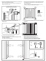
3 . Insert the Bolts with Rubber Pads and Tension Knobs into the Gate
Frame. 3. Deslice los pernos con las almohadillas de goma en el marco de la
compuerta.
4. Place the gate in the opening so that the bottom of the Gate Frame is
completely flat on the floor, and it is perpendicular to the opening and
the floor.
4. Coloque la barrera en la abertura de modo que la parte inferior del
marco de compuerta esté completamente plana sobre el piso, y esté
perpendicular a las aberturas y el piso.
x 4
E
x 4
F
Wall/Pared
Wall/Pared
Wall/Pared
Wall/Pared
5A
5.
Tighten both of the lower Tension Knobs (E) by turning them at the
same time.
NOTE: Make sure the bottom of the gate frame remains
completely flat on the floor.
Next, tighten both of the upper Tension Knobs by turning them at
the same time.
5.
Apriete ambas perillas de tensión (E) inferior girándolas en el sentido
de las agujas del reloj al mismo tiempo.
NOTA: Asegúrese de que la parte inferior del marco de la compuerta
permanezca completamente plana sobre el piso.
A continuación, apriete ambas Perillas de tensión en la parte superior
al mismo tiempo girándolos en el sentido de las agujas del reloj.
5B 5C
NOTE:
When first installing,
the gate will have this
gap. This is normal and
will disappear when
gate is completely
installed.
NOTA:
La brecha (espacio
intermedio) en esta
compuerta no es un
defecto.
La brecha desaparecerá
cuando la compuerta esté
correctamente instalada.
Tighten inward
Apretar hacia adentro
DE
Tighten inward
Apretar hacia adentro
Tighten inward
Apretar hacia adentro
Tighten inward
Apretar hacia adentro
Tighten inward
Apretar hacia adentro
5

G x 4
H x 4
G
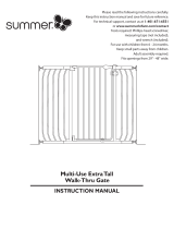
Distance should
be equal
La distancia
debe ser igual
Y=Y
X=X
Indicator
Lines
Pontos de
indicadores
Keep this gap about 0.04in (1mm)
Mantenga esta brecha alrededor de
0.04in (1mm)
Y
X
Y
X
6. Tighten the Tension Knobs until the two Indicator Lines, located on the
Upper Locking Set (B) align horizontally.
When correctly tightened, the distances between Tension Knobs and
Rubber Pads should be equal.
6. Apriete las perillas de tensión hasta las 2 líneas indicadoras, ubicadas
en el juego de cierre superior (B) y en la esquina superior derecha,
alinee horizontalmente.
Cuando se aprietan correctamente, las distancias entre las perillas de
tensión y las almohadillas de goma deben ser iguales.
7. Use a pencil to mark around the ends of the 4 Bolts with
Rubber Pads (F). 7. Usa un lápiz para marcar alrededor de 4 pernos con las almohadillas
de goma (F).
8. Loosen the Tension Knobs and remove Gate.
Add tape (H) to Wall Cups (G) Line up Wall cups with marks on wall.
Check gate is in alignment.
Press Wall Cups (G) firmly into place.
8. Afloje los pernos de tensión y retire la compuerta.
Agregue cinta (H) a las Copas de Pared (G),
alinee las Copas de Pared a las marcas en la pared.
Verifique que la compuerta esté completamente alineada.
Presione firmemente las Copas de Pared (G) en su lugar.
B
F
6

Y
X
Y
X
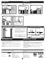
9 Screw Wall Cups (G) into place. 9 Atornille las Copas de Pared (G) en su lugar.
10. Reinstall gate inserting Bolts with Rubber Pads into Wall Cups (G). 10. Vuelva a instalar la compuerta, insertando los pernos con las
almohadillas de goma en las Copas de Pared( G).
F
Ensure the surface you mount the gate to is structurally sound such as solid
timber, brick or masonry.
For plaster / gyprock surface, locate the timber beam or stud behind and
mount in this location (mounting on plaster / gyprock alone is not strong
enough and not safe).
DO NOT MOUNT TO GLASS.
Asegúrese que la superficie sobre la que ubica la compuerta es
estructuralmente sólida, tal como madera maciza, ladrillos o mampostería.
Para superficies de yeso/gyprock, encuentre el travesaño o tabla interna y
fije en ese lugar (montarla directamente sobre yeso o gyprock no es lo
suficientemente fuerte, además de ser inseguro).
NO UBICAR EN VIDRIO.
Keep this gap about 1mm/0.04in
Mantenga esta brecha alrededor de 1mm
Distance
should be
equal
La distancia
debe ser igual
Y=Y
X=X
Indicator
Lines
Pontos de
indicadores
B
x 4
J
G x 4 J x 4
H x 4
You MUST install wall cups, with screws, to keep the
gate in place. Without wall cups, child can push out
and escape.
DEBE instalar las copas de pared con tornillos para
mantener la puerta de seguridad en su lugar.
Sin las copas de pared, el niño puede empujar la
puerta de seguridad y escapar.
Wood Screws (J) included. For Brick or
Masonry use the appropriate fittings, screws
and plugs for your wall. (not included)
Tornillos para madera (J) incluidos. Para
ladrillo o mampostería, use los accesorios,
tornillos y enchufes apropiados para su
pared (no incluidos).
7

L854.L867.L919.L1961.L1962.L1963.L1964_L776_IM_pages1-8_16.11_2020_X.04
• Gate must be fitted according to instructions, to ensure it works correctly.
• Regularly check tension knobs and rubber pads to make sure the gate is
securely in place. Adjust as required.
• Any additional and replacement parts should be obtained from Tee-Zed
Products.
• To clean, wipe surface with a damp cloth or sponge using mild detergent and
warm water.
Never clean with abrasive, ammonia based bleach based or spirit type
cleaners.
• Se debe ajustar la barrera según las instrucciones, para asegurar que
funcione correctamente.
• Periódicamente revise las perillas de tensión y almohadillas de goma para
asegurarse de que la barrera esté segura en su lugar. Ajuste si es necesario.
• Cualquier parte adicional o de reemplazo se puede obtener por medio
de Tee-Zed Products.
• Para limpiar, pase un paño o esponja húmedos sobre la superficie, usando un
detergente suave y agua tibia.
No use nunca limpiadores abrasivos a base de amoníaco o alcohol
desnaturalizado.
MAINTENANCE & CARE MANTENIMIENTO Y CUIDADO
©2021 Tee-Zed Products, LLC
Dreambaby
®
products by
Los productos Dreambaby
®
por
Made in Hangzhou, China.
Hecho en China.
TEE-ZED PRODUCTS, LLC ACCEPTS NO RESPONSIBILITY FOR ANY LOSS OR DAMAGE SUFFERED BY ANY PERSON AS A
RESULT OF THE USE OR MISUSE OF THESE GOODS. IN THE CASE OF ANY DEFECT IN THE GOODS, TEE-ZED’S LIABILITY
SHALL BE LIMITED SOLELY TO REPLACEMENT OF THE DEFECTIVE GOODS.
TEE-ZED PRODUCTS, LLC NO SE HACE RESPONSABLE DE NINGUNA PÉRDIDA O DAÑO SUFRIDO POR ALGUNA PERSONA
COMO RESULTADO DEL USO O DE LA MALA UTILIZACIÓN DE ESTAS MERCANCÍAS. EN CASO DE CUALQUIER DEFECTO
EN LAS MERCANCÍAS, LA RESPONSABILIDAD DE TEE-ZED’S SERÁ LIMITADA ÚNICAMENTE AL REEMPLAZO DE LAS
MERCANCÍAS DEFECTUOSAS.
Tee-Zed Products Pty Ltd
PO Box 2022,
Bondi Junction NSW 1355
Australia
+61 (0)2 9386 4000
info@tee-zed.com.au
www.dreambaby.com.au
Tee-Zed Products, LLC
PO Box 1662, Jamestown, NC 27282
USA
(336) 454-5716,
Toll free: 888-271-6959
info@tee-zed.com
www.dream-baby.com
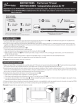
OPERATION OPERACIÓN
1
To open the gate:
1
Para abrir la compuerta:
2
To close the gate:
This safety gate has a manual close system.
Make sure the Upper and Lower Locking sets are engaged.
2
Para cerrar la compuerta:
Cierre la hasta que quede totalmente bloqueada con los juegos de bloqueo superior e
inferior enganchados.
2A 2B
B
A
A
I
1B
1A 1C
C
Lift Gate Panel up to open
Levante el panel de la
puerta hacia arriba
Slide
Deslice
Release
Switch
Interruptor
de liberación
A
SMART STAY-OPEN SYSTEM
SISTEMA “PERMANECER ABIERTO”
To engage the Smart Stay Open System swing gate in
chosen direction to its maximum opening. Gate will
stay open. Close as required.
Para activar el Característica de permanecer abierta,
abra la compuerta con un vaivén en la dirección
escogida hasta llegar a su apertura maxima. La barrera
permenecera abierta.Cierrela como se pide.
CAUTION: Keep gate closed when children
are present.
PRECAUCIÓN: Mantenga la barrera cerrada
cuando haya niños presentes.
Gate in CLOSED position
Barrera en posición CERRADA
Swing to OPEN positions
Balancee a la posición ABIERTA
TOP VIEW OF GATE
VISTA SUPERIOR DE LA COMPUERTA
8
-
 1
1
-
 2
2
-
 3
3
-
 4
4
-
 5
5
-
 6
6
-
 7
7
-
 8
8


Dreambaby L867 User manual
- Type
- User manual
- This manual is also suitable for
Ask a question and I''ll find the answer in the document
Finding information in a document is now easier with AI
in other languages
- español: Dreambaby L867 Manual de usuario
Related papers


Other documents
-
 Summer by Ingenuity Extra Tall Décor Safety Gate Owner's manual
-
 Summer by Ingenuity Anywhere Decorative Walk-Thru Gate Owner's manual
-
 Summer by Ingenuity Multi-Use Decorative Extra Tall Walk-Thru Baby Gate - Beige Owner's manual
-
Carlson 0941 PW DS User manual
-
-
-
Regalo 1165 W DS Operating instructions
-
-
Regalo 1350 User manual
-


