Page is loading ...

IO-Link Parameter Datasheet
Encoder
Absolute rotary encoder
ENA42HT-S*9-00* series
Support: fa[email protected]
Internet: www.pepperl-fuchs.com
DOCT-9076 - Version 1.00.000 / 2023-12-06
General Information
Device Identification
Vendor ID
1 (0x0001)
Device ID
500102 (0x5246978)
Communication Characteristics
IO-Link revision
V1.1 (specification V1.1.2)
IO-Link backward compatibility
n/a
Data transmission rate
COM3 (230.4 kbit/s)
Min. cycle time
1.5 ms
Process data input
12 byte
Process data output
n/a
SIO mode support
no
Compatible master port type
Class A, Class B (see NOTE)
NOTE: For use at IO-Link master port Class B, use 3-pole adapter or 3-wire cable.
Features
Data storage
Yes
Block parameterization
Yes
Device Profile
Identification & Diagnosis – I&D
16384 (0x4000)
Supported Product Variants
Product ID
Product Name
Description
Connector
70119037-100502
ENA42HT-S10S49-0016-IO-ABD01
Absolute rotary heavy duty encoder, housing size 42, solid
diameter 10 mm, flange servo V4A, IP69, single-turn resolution
16 bit, axial connection, M12 5-pole
Plug, M12, 5-pole
70119037-100503
ENA42HT-S10S49-0016-IO-RBD01
Absolute rotary heavy duty encoder, housing size 42, solid
diameter 10 mm, flange servo V4A, IP69, single-turn resolution
16 bit, radial connection, M12 5-pole
Plug, M12, 5-pole
70119037-100506
ENA42HT-S10C49-0016-IO-ABD01
Absolute rotary heavy duty encoder, housing size 42, solid
diameter 10 mm, flange clamping V4A, IP69, single-turn
resolution 16 bit, axial connection, M12 5-pole
Plug, M12, 5-pole
70119037-100507
ENA42HT-S10C49-0016-IO-RBD01
Absolute rotary heavy duty encoder, housing size 42, solid
diameter 10 mm, flange clamping V4A, IP69, single-turn
resolution 16 bit, radial connection, M12 5-pole
Plug, M12, 5-pole
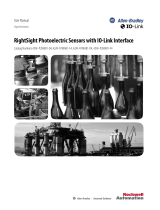
Connection
Connection Diagram
Description
Plug, M12, 5-pole
1: Brown - +24V
2: White - reserved, do not connect
3: Blue - 0V
4: Black - C/Q
5: Grey - n.c.

Process Data
Process Data Input
Sub
Name
Data type
Length
Bitoffs.
Value
Unit
Description
.1
SSC1 - Switching Signal
String
1 bit
0
Indicates the current status of the switching signal 1.
0
1
Low
High
.2
SSC2 - Switching Signal
Bool
1 bit
1
Indicates the current status of the switching signal 2.
0
1
Low
High
.3
Status - Count Direction
Bool
1 bit
2
Indicates the current status of the direction of position count.
0
1
Increase
Decrease
.5
Status - Auxiliary
Measurement MDC2
UInteger
4 bit
4
Indicates the currently selected source for the auxiliary
measurement channel MDC2.
0
1
Deactivated
Temperature
.9
DSC1.1 - Temperature
Warning
Bool
1 bit
8
Indicates that the configured temperature threshold has been
exceeded.
0
1
Low
High
.10
DSC1.2 - Temperature
Warning
Bool
1 bit
9
Indicates that the configured temperature threshold has been
undershot.
0
1
Low
High
.17
MDC1 - Resolution (STR)
UInteger
16 bit
16
STR
value
Indicates the current resolution of the position value.
.18
MDC1 - Position
Integer
32 bit
32
POS
value
Indicates the current position value.
.19
MDC2 - Auxiliary
Measurement
Integer
32 bit
64
AUX
value
Indicates the measurement value of the selected auxiliary
measurement channel MDC2.
NOTE: The process data input content can be accessed in addition over parameter ‘Process Data Input’ at index 40 (0x28)
Parameter Data
Identification
Index
Parameter
Access
Data type
Length
Default
Description
DS
R
16 (0x10)
Vendor Name
ro
String
13 byte
Pepperl+Fuchs
The vendor name that is assigned
to a Vendor ID.
17 (0x11)
Vendor Text
ro
String
29 byte
www.pepperl-fuchs.com/io-link
Additional information about the
vendor.
18 (0x12)
Product Name
ro
String
max.
30 byte
ENA42HT-S*9-00*
See table
Supported Product Variants
Complete product name.
19 (0x13)
Product ID
ro
String
13 byte
70119037-*
See table
Supported Product Variants
Vendor-specific product or type
identification (e.g., item number or
model number).
20 (0x14)
Product Text
ro
String
max.
30 byte
Absolute rotary encoder
Additional product information for
the device.
21 (0x15)
Serial Number
ro
String
14 byte
Unique, vendor-specific identifier of
the individual device.
22 (0x16)
Hardware Revision
ro
String
7 byte
HW**.**
Unique, vendor-specific identifier of
the hardware revision of the
individual device.
23 (0x17)
Firmware Revision
ro
String
7 byte
FW**.**
Unique, vendor-specific identifier of
the firmware revision of the
individual device.
24 (0x18)
Application Specific Tag
rw
String
max.
32 byte
Your automation, our passion.
Possibility to mark a device with
user- or application-specific
information.
Y
F
25 (0x19)
Function Tag
rw
String
max.
32 byte
***
Possibility to mark a device with
function-specific information.
Y
F
26 (0x1A)
Location Tag
rw
String
max.
32 byte
***
Possibility to mark a device with
location-specific information.
Y
F

Diagnosis
Index
.sub
Parameter
Access
Data type
Length
Bitoffs.
Default
Value
Unit
Description
DS
R
36 (0x24)
Device Status
ro
UInteger
8 bit
0
Indicator for the current device
condition and diagnosis state.
FA
0
1
2
3
4
Device is OK
Maintenance required
Out of Specification
Functional check
Failure
37 (0x25)
Detailed Device Status
ro
Array S0
12 byte
List of all currently pending events
in the device.
FA
.1
Element 1
Octetstr
3 byte
36
0
.2
Element 2
Octetstr
3 byte
24
0
.3
Element 3
Octetstr
3 byte
12
0
.4
Element 4
Octetstr
3 byte
0
0
127
(0x7F)
Indication Control
rw
Record S0
8 bit
Provides control functions for
diagnosis purposes for indicators
or display.
FA
.1
Locator Indication
rw
Boolean
1 bit
0
0
Enables a defined flashing pattern
of the indicator LEDs for better
spotting of a device in field
applications.
FA
0
1
Disabled
Enabled
224
(0xE0)
Operating Hours
ro
UInteger
32 bit
0 ..
232-1
Shows the overall hours of
operation since initial
commissioning.
225
(0xE1)
Temperature Indicator
ro
UInteger
8 bit
Indicates the operation at critical
ambient temperatures or excess of
specification limits.
0
1
2
3
4
Operating condition OK
Close to upper limit
Upper limit exceeded
Close to lower limit
Lower limit exceeded
232
(0xE8)
Device Characteristic
ro
Record S0
6 byte
Shows relevant key characteristics
of the device for use in
applications.
.1
ST Resolution (bit)
ro
UInteger
16 bit
32
Shows the maximum configurable
resolution for a single turn in
counts: 2^STR-1.
.2
MT Resolution (bit)
ro
UInteger
16 bit
16
Shows the maximum number of
detectable revolutions:
2^MTR-1.
.3
Supply Current
Requirement
ro
UInteger
16 bit
0
mA
Shows the maximum specified
supply current excluding load.

Parameterization & Configuration
Index
.sub
Parameter
Access
Data type
Length
Bitoffs.
Default
Value
Unit
Description
DS
R
64 (0x40)
SSC1.1 Param - Position
rw
Record
8 byte
Defines the setpoint values for
switching signal channel 1.1.
Y
FA
.1
SP1
rw
Integer
32 bit
32
0
0 ..
231-1
Defines the setpoint 1 value for the
switching signal channel.
Y
FA
.2
SP2
rw
Integer
32 bit
0
0
0 ..
231-1
Defines the setpoint 2 value for the
switching signal channel.
Y
FA
65 (0x41)
SSC1.1 Config - Position
rw
Record
4 byte
Defines the configuration
parameter for switching signal
channel 1.1.
Y
FA
.1
Logic
rw
UInteger
8 bit
24
0
Defines the logical behavior of the
switching signal.
Y
FA
0
1
High active
Low active
.2
Mode
rw
UInteger
8 bit
16
0
Defines the evaluation mode for
the switching signal.
Y
FA
0
1
2
3
Deactivated
Single point
Window
Two point
.3
Hyst
rw
Integer
16 bit
0
0
0 ..
215-1
Defines the hysteresis at the
switchpoint. A higher hysteresis
may help to improve the stability in
critical applications.
Y
FA
66 (0x42)
SSC1.2 Param - Position
rw
Record
8 byte
Defines the setpoint values for
switching signal channel 1.2.
Y
FA
.1
SP1
rw
Integer
32 bit
32
0
0 ..
231-1
Defines the setpoint 1 value for the
switching signal channel.
Y
FA
.2
SP2
rw
Integer
32 bit
0
0
0 ..
231-1
Defines the setpoint 2 value for the
switching signal channel.
Y
FA
67 (0x43)
SSC1.2 Config - Position
rw
Record
4 byte
Defines the configuration
parameter for switching signal
channel 1.2.
Y
FA
.1
Logic
rw
UInteger
8 bit
24
0
Defines the logical behavior of the
switching signal.
Y
FA
0
1
High active
Low active
.2
Mode
rw
UInteger
8 bit
16
0
Defines the evaluation mode for
the switching signal.
Y
FA
0
1
2
3
Deactivated
Single point
Window
Two point
.3
Hyst
rw
Integer
16 bit
0
0
0 ..
215-1
Defines the hysteresis at the
switchpoint. A higher hysteresis
may help to improve the stability in
critical applications.
Y
FA
80 (0x50)
DSC1 Param -
Temperature
rw
Record
4 byte
Defines the thresholds for
temperature warnings in the
diagnosis signal channel DSC1.
Y
FA
.1
High Limit
rw
Integer
16 bit
16
70
-45 ..
90
°C
Defines the upper temperature
threshold. At ambient
temperatures above this limit, the
diagnosis flag 'DSC1.1 -
Temperature Warning' in the
process data is activate. An event
is triggered, if enabled.
Y
FA
.2
Low Limit
rw
Integer
16 bit
0
-30
-45 ..
90
°C
Defines the lower temperature
threshold. At ambient
temperatures below this limit, the
diagnosis flag 'DSC1.2 -
Temperature Warning' in the
process data is activate. An event
is triggered, if enabled.
Y
FA

Parameterization & Configuration
Index
.sub
Parameter
Access
Data type
Length
Bitoffs.
Default
Value
Unit
Description
DS
R
81 (0x51)
DSC1 Config -
Temperature
rw
Record
4 byte
Defines the configuration
parameter for diagnosis signal
channel DSC1.
Y
FA
.1
Logic
rw
UInteger
8 bit
24
0
Defines the logical behavior of the
switching signal.
Y
FA
0
1
High active
Low active
.2
Mode
rw
UInteger
8 bit
16
0
Defines the evaluation behavior of
the diagnosis signal channel 1.
Y
FA
0
1
2
Deactivated
High limit active
High and low limit active
.3
Hyst
rw
Integer
16 bit
0
0
0 ..
20
°C
Defines the hysteresis at the
temperature thresholds.
Y
FA
96 (0x60)
Config - Resolution
rw
UInteger
16 bit
216-1
0 ..
216-1
Defines the single-turn resolution
in counts per revolution.
Y
FA
97 (0x61)
Config - Rotation
Direction
rw
UInteger
8 bit
0
Defines the counting direction for
the position - clockwise: position
increases on clockwise rotation /
counter clockwise: position
decreases on clockwise rotation.
Y
FA
0
1
Clockwise
Counter clockwise
99 (0x63)
Config - Position Preset
rw
Integer
32 bit
0
0 ..
231-1
Defines the preset value, which is
set for the current position on
trigger of the command 'Position
Preset'. Resolution is in counts.
Y
FA
101
(0x65)
Config - Auxiliary
Measurement
rw
UInteger
8 bit
0
Defines the source for the auxiliary
measurement channel MDC2.
Y
FA
0
1
Deactivated
Temperature
120
(0x78)
Event Config
rw
Record S0
2 byte
Defines which event sources can
trigger events.
Y
FA
.1
Position Channel 1
Diagnosis
rw
Boolean
1 bit
24
0
Enabled: an event is generated, if
the position value is outside the
configured application specific
position limits for channel 1.
Y
FA
0
1
Disabled
Enabled
.2
Position Channel 2
Diagnosis
rw
Boolean
1 bit
16
0
Enabled: an event is generated, if
the position value is outside the
configured application specific
position limits for channel 2.
Y
FA
0
1
Disabled
Enabled
.3
Temperature
Diagnosis
rw
Boolean
1 bit
0
0
Enabled: an event is generated, if
the detected temperature is
outside the configured application
specific temperature limits.
Y
FA
0
1
Disabled
Enabled

Observation
Index
.sub
Parameter
Access
Data type
Length
Bitoffs.
Default
Value
Unit
Description
DS
R
36 (0x24)
Device Status
ro
UInteger
8 bit
0
Indicator for the current device
condition and diagnosis state.
FA
0
1
2
3
4
Device is OK
Maintenance required
Out of Specification
Functional check
Failure
236
(0xEC)
Measurement Data
ro
Record S0
Shows a collection of relevant
measurement and process data.
.1
MDC1 - Position
ro
Integer
32 bit
136
0
POS
value
Indicates the current position
value.
.2
MDC1 - ST Resolution
ro
Integer
16 bit
120
0
STR
value
Indicates the current resolution of
the position value.
.3
MDC2 - Temperature
ro
Integer
32 bit
88
0
TEMP
value
°C
Indicates the current approximated
ambient temperature value.
.8
DSC1.2 –
Temperature Warning
ro
UInteger
8 bit
32
0
Indicates that the configured
temperature threshold has been
undershot.
0
1
Low
High
.7
DSC1.1 –
Temperature Warning
ro
UInteger
8 bit
24
0
Indicates that the configured
temperature threshold has been
exceeded.
0
1
Low
High
.6
Status –
Count Direction
ro
UInteger
8 bit
16
0
Indicates the current status of the
direction of position count.
0
1
Increase
Decrease
.5
SSC2 –
Switching Signal
ro
UInteger
8 bit
8
0
Indicates the current status of the
switching signal 2.
0
1
Low
High
.4
SSC1 –
Switching Signal
ro
UInteger
8 bit
0
0
Indicates the current status of the
switching signal 1.
0
1
Low
High
NOTE 1: The parameter data provide the attributes DS (Data Storage) and R (Reset behavior). The following rules apply:
DS: Parameter marked with ‘Y’ (yes) are exchanged with the master via the data storage mechanism.
R: Parameter marked with ‘F’ are reset to the default value upon reception of the command ‘Restore Factory Settings’.
R: Parameter marked with ‘A’ are reset to the default value upon reception of the command ‘Application Reset’.
NOTE 2: Parameter with datatype Record or Array, which are marked with ‘S0’ can only be accessed over subindex 0 (whole parameter object). Subindex access to single
items is not possible.
Command Interface
Index/.sub
Parameter
Access
Data type
Length
Value
Description
2 (0x02)
System
Command
wo
UInteger
8 bit
See
command
value
Command interface for applications. A positive acknowledge indicates the
complete and correct finalization of the requested function.
Command
Value
Command
Description
129 (0x81)
Application Reset
The parameter of the technology-specific application are set to default values. Identification parameter
remain unchanged. An upload to the data storage of the master will be executed, if activated in the port
configuration of the master.
130 (0x82)
Restore Factory Settings
The parameter of the device are reset to factory settings. Note: A download of the data storage may be
executed on the next power cycle and overwrite the factory default settings!
170 (0xA0)
Position Preset
The position value at the current position is set to the position preset value.

Error Codes
Code
Additional
code
Name
Description
128 (0x80)
17 (0x11)
Index not available
Read or write access attempt to a non-existing index.
128 (0x80)
18 (0x12)
Subindex not available
Read or write access attempt to a non-existing subindex of an existing
index.
128 (0x80)
32 (0x20)
Service temporarily not available
Parameter not accessible due to the current state of the technology-
specific application.
128 (0x80)
33 (0x21)
Service temporarily not available - local control
Parameter not accessible. The device is currently in an ongoing,
locally controlled operation.
128 (0x80)
34 (0x22)
Service temporarily not available - device control
Parameter not accessible. The technology-specific application is
currently in a remotely triggered operation.
128 (0x80)
35 (0x23)
Access denied
Write access to a read-only parameter or read access to write-only
parameter.
128 (0x80)
48 (0x30)
Parameter value out of range
Written parameter value is outside of the permitted value range.
128 (0x80)
49 (0x31)
Parameter value above limit
Written parameter value is above its specified value range.
128 (0x80)
50 (0x32)
Parameter value below limit
Written parameter value is below its specified value range.
128 (0x80)
51 (0x33)
Parameter length overrun
Written parameter is longer than specified.
128 (0x80)
52 (0x34)
Parameter length underrun
Written parameter is shorter than specified.
128 (0x80)
53 (0x35)
Function not available
Written command is not supported by the technology-specific
application.
128 (0x80)
54 (0x36)
Function temporarily unavailable
Written command is unavailable due to the current state of the
technology-specific application.
128 (0x80)
64 (0x40)
Invalid parameter set
Written single parameter value collides with other existing parameter
settings.
128 (0x80)
65 (0x41)
Inconsistent parameter set
Parameter set inconsistencies at the end of block parameter transfer.
Device plausibility check failed.
Event Codes
Code
Type
Name
Description
36163 (0x8d43)
Warning
Ambient temperature outside
specified temperature range
Check device environment.
36176 (0x8d50)
Warning
Position channel 1 diagnosis
Position value outside configured application specific position limits
for channel 1. Check adjustment or application.
36177 (0x8d51)
Warning
Position channel 2 diagnosis
Position value outside configured application specific position limits
for channel 2. Check adjustment or application.
36178 (0x8d52)
Warning
Temperature diagnosis
Temperature exceeds configured application specific temperature
limits. Check environment or application.
/