Jacuzzi J?SN180F Operating instructions

Category
Water heaters & boilers
Type
Operating instructions

This manual is also suitable for

Donotstoreorusegasolineorotherammablevaporsandliquidsinthevicinityofthisoranyother
appliance.
WHATTODOIFYOUSMELLGAS
Donottrytolightanyappliance.
Donottouchanyelectricalswitch;donotuseanyphoneinyourbuilding.
Immediatelycallyourgassupplierfromaneighbor’sphone.Followthegassupplier’sinstrucons.
Ifyoucannotreachyourgassupplier,calltheredepartment.
Installaonandservicemustbeperformedbyalicensedprofessional.
Thisenremanualmustbelefortheconsumer.Theconsumermustreadand
refertothismanualforproperoperaonandtomaintainthewaterheater.
JSN180F
JSP180F
JSN199F
JSP199F
DirectVentTanklessWaterHeater
InstallaonandOperaonManual
ANSZ21.10.3●CSA4.3
Iftheinformaonintheseinstruconsisnotfollowedexactly,areorexplosion
mayresultcausingpropertydamage,personalinjuryordeath.
WARNING
ReadthisManual
Thismanualprovidesinformaonontheinstallaon,operaon,andmaintenanceofthewaterheater.Forproper
operaonandsafety,itisimportanttofollowtheinstruconsandadheretothesafetyprecauons.
Instruconsonproperinstallaonandregularmaintenanceofthewaterheatershouldbef
ollowedtoproperly
operatethewaterheaterandtomaintainthewarranty.
Readalloftheinstruconsthoroughlybeforeinstallingoroperangthiswaterheater.
SignatureTanklessWaterHeaters
2 JS180F/JS199F
TableofContents
Thisisthesafetyalertsymbol.Thissymbolalertsyoutopotenalhazardsthatcankillorhurtyou
andothers.
Indicatesanimminentlyhazardoussituaonwhich,ifnotavoided,willresultindeathor
seriousinjury.
Indicatesapotenallyhazardoussituaonwhich,ifnotavoided,couldresultindeathor
seriousinjury.
Indicatesapotenallyhazardoussituaonwhich,ifnotavoided,couldresultinminoror
moderateinj
ury.Itmayalsobeusedtoalertagainstunsafepracces.
DANGER
CAUTION
WARNING
TableofContents.....................................................2
SafetyBehaviorsandPraccesforthe
ConsumerandInstaller............................................3
InstallaonInstrucons........................................4
PrepareforInstallaon......................................5
DetermineInstallaonLocaon........................6
ChecklisttoDetermineInstallaonLocaon...11
MounttoWall..................................................11
RemovetheFrontPanel..................................11
InstallaonofVenng.....................................12
InstallaonofCondensateTrap......................14
ChecklistforVenngandCondensate ............14
InstallaonofPlumbi
ng...................................15
ChecklistforPlumbing.....................................17
InstallaonofGasSupply................................17
ConnectEle
ctricity...........................................19
AdjustforHighAltude...................................19
ChecklistforGasandElectricity......................19
InstallaonofTemperatureController...........20
FinalChecklist..................................................21
TechnicalData........................................................22
Specicaons...................................................22
Dimensions......................................................23
PressureDropandWaterFlowCurves............24
LadderDiagr
am................................................25
OperaonInstrucons.......................................26
ConsumerOperaonGuidelinesforthe
SafeOperaonofyourWaterHeater....................27
OperangInstrucons...........................................28
HowtoSettheTemperature...........................29
UsingtheBathFillFuncon.............................31
DiagnoscCodes..............................................33
Requir
edMaintenance...........................................35
FlushingtheHeatEx changer...........................37
ManualDrainingoftheWaterHeater.............38
StateRegulaons...................................................39
ReplacementParts.................................................40
ConsumerWarranty...............................................41
ImportantSafetyInformaon
SafetyDenions
Jacuzzisomemessharescustomercontactinformaonwithbusinessesthatwebelieveprovideproductsor
servicesthatmaybeusefultoyou. Byprovidingthisinformaon,youagreethatwecanshareyourcontact
informaonforthispurpose.Ifyouprefernottohaveyourinformaonsharedwiththesebusinesses,please
contac
tcustomerserviceandasknottohaveyourinformaonshared.Wewillhowever,connuetocontact
youwithinformaonrelevanttotheproduct(s)youregisteredand/oryouaccountwithus.
JS180F/JS199F 3
SafetyBehaviorsandPraccesfortheConsumerandInstaller
Toprotectyourselffromharm,beforeperforming
maintenance:
Turnofftheelectricalpowersupplyby
unpluggingthepowercordorbyturningoffthe
electricityatthecircuitbreaker.(The
temperaturecontrollerdoes notcontrolthe
electricalpower.)
Turnoffthegasatthemanualgasvalve,
usuallylocatedimmediatelybelowthewater
heater.
Turnofftheincomingwatersupply.Thiscan
bedoneattheisolaonvalveimmediately
belowthewaterheaterorbyturningoffthe
watersupplytothebuilding.
Beforeoperang,smellallaroundtheappliance
areaforgas.Besuretosmellnexttotheoor
becausesomegasisheavierthanairandwillsele
ontheoor.
Useonlyyourhandtopushinorturnthegas
controlknob.Neverusetools.Iftheknobwillnot
pushinorturnbyhand,donottrytorepairit;call
alicensedprofessional.Forceoraemptedrepair
mayresultinareorexplosion.
Keeptheareaaroundtheapplianceclearandfree
fromcombusblematerials,gasoline,andother
ammablevaporsandliquids.
Anyalteraontotheappliance oritscontrolscan
bedangerousandwillvoidthewarranty.
Alwayscheckthewatertemperaturebefore
enteringashowerorbath.
Donotusethisapplianceifanyparthasbeen
underwater.Immediatelycallalicensed
professionaltoinspecttheapplianceandtoreplace
anypartofthecontrolsystemandanygascontrol
whichhasbeenunderwater.
Donotusesubstutematerials.Useonlyparts
ceredwiththeappliance.
Combusbleconstruconreferstoadjacentwalls
andceilingandshouldnotbeconfusedwith
combusbleorammableproductsandmaterials.
Combusbleand/orammableproductsand
materialsshouldneverbestoredinthevicinityof
thisoranygasappliance.
DonotadjusttheDIPswitchunlessspecically
instructedtodoso.
Shouldoverheangoccurorthegassupplyfailto
shuto,turnoffthemanualgascontrolvalveto
theappliance.
Donotuseanextensioncordoranadapterplug
withthisappliance.
WARNING
CAUTION
BURNHAZARD.Hotexhaustandventmaycause
seriousburns.Keepbackfromwaterheaterunit.
Keepsmallchildrenandanimalsawayfromunit.
Hotwateroutletpipes leavingtheunitcanbehot
totouch.Inresidenalapplicaons,insulaon
mustbeusedforhotwaterpipesbelow36”dueto
burnrisktochildren.
Californialawrequiresthisnocetobeprovided:
CaliforniaProposion65 listschemicalsubstancesknowntothestatetocausecancer,birthdefects,death,
seriousillnessorotherreproducveharm.Thisproductmaycontainsuchsubstances,betheiroriginfromfuel
combuson(gas,oil)orcomponentsoftheproducti
tself.
4 JS180F/JS199F
Alicensedprofessionalshouldinstalltheappliance,
inspectit,andleaktestitbeforeuse.Thewarranty
willbevoidedduetoimproperinstallaon.
Theinstallershouldhaveskillssuchas:
gassizing
connecnggaslines,waterlines,valves,
electricity,
knowledgeofapplicablenaonal,state,and
localcodes.
installingvenngthroughawallorroof
Ifyoulacktheseskillscontactalicensedprofessional.
InstallaonInstrucons
InstallaonSteps
PrepareforInstallaon......................................5
DetermineInstallaonLocaon........................6
ChecklisttoDetermineInstallaonLocaon...11
MounttoWall..................................................11
RemovetheFrontPanel..................................11
InstallaonofVenng......................................12
InstallaonofCondensateTrap.......................14
ChecklistforVenngandCondensate .............14
InstallaonofPlumbi
ng...................................15
ChecklistforPlumbing.....................................17
InstallaonofGasSupply................................17
ConnectElectricity...........................................19
AdjustforHighAltude...................................19
ChecklistforGasandElectricity.......................19
InstallaonofTem
peratureController............20
FinalChecklist..................................................21
GeneralInstruconsInstallerQualicaons
DONOT
Donotinstalltheapplia nce outdoors.
Donotinstalltheapplia nce inanareawherewater
leakageoftheunitorconneconswillresultin
damagetotheareaadjacenttotheapplianceorto
loweroorsofthestructure.Whensuchlocaons
cannotbeavoided,itisrecommendedthata
suitabledrainpan,adequatelydrai
ned,beinstalled
undertheappliance.Thepanmustnotrestrict
combusonairow.
Donotobstructtheowofcombusonand
venlaonair.Combusonairshallnotbe
suppliedfromoccupiedspaces.
Donotusethisapplianceinanapplicaonsuchas
apoolorspaheaterthatuseschemicallytreated
water.(Thisapplianceissuitableforllinglargeor
whirlpoolspatubswithpotablewa ter.)
Donotusesubstutepartsthatarenotauthorized
forthisappliance.
MUSTDO
Theinstallaonmustconformwithlocalcodesor,
intheabsenceoflocalcodes,withtheNaonal
Fuel Gas Code, ANSI Z223.1/NFPA 54.Ifinstalledin
amanufacturedhome,theinstallaonmust
conformwiththeManufactured Home
Construcon and Safety Standard, Title 24 CFR,
Part 3280.
Theappliance,wheninstalled,mustbeelectrically
groundedinaccordancewithlocalcodesor,inthe
absenceoflocalcodes,withtheNaonal Electrical
Code, ANSI/NFPA 70.
Theapplianceanditsappliancemaingasvalve
mustbedisconnectedfromthegassupplypiping
systemduringanypressuretesngofthatsystem
attestpressuresinexcessof1/2psi(3.5kPa)
(13.84inW.C.).
Theappliancemustbeisolatedfromthegassupply
pipingsystembyclosingitsindividualmanual
shutoffvalveduringanypressuretesngofthegas
supplypipingsystemattestpressuresequaltoor
lessthan1/2psi(3.5kPa)(13.84inW.C.).
TypeofInstallaon
Forinstallaoninresidenalandcommercial
applicaons.
Ceredforinstallaoninmanufactured(mobile)
homes.
JS180F/JS199F 5
PrepareforInstallaon
Partsincluded
Toolsneeded
Materialsneeded
Youmustfollowtheinstallaoninstruconsand
thoseinCare and Maintenanceforadequate
combusonairintakeandexhaust.
INFORMATION
Ifawaterheateris installedinaclosedwater
supplysystem,suchasonehavingabackow
preventerinthecoldwatersupplyline,means
shallbeprovidedtocontrolthermalexpansion.
Contactthewatersupplierorlocalplumbing
inspectoronhowtocontrolthermal expansion.
Shouldoverheangoccurorthegassupplyfailto
shuto,turnoffthemanualgascontrolvalveto
theappliance.
Keeptheairintakelocaonfreeofchemicalssuch
aschlorineorbleachthatproducefumes.These
fumescandamagecomponentsandreducethelife
ofyourappliance.
Tanklesswaterheater
Pipewrenches(2)
Adjustablepliers
Screwdrivers(2)
Wirecuers
Gloves
Safetyglasses
Toolsthatmightbeneeded
Hammerdrillwith
concretebits
Saw
Threadingmachinewith
headsandoiler
Coredrillwithdiamond
head
Torchset
Coppertubingcuer
Steelpipe cuer
Materialsthatmaybeneeded
Soapsoluon
Approvedvenng
Teontape
(recommended)orpipe
compound
Heattape
Pipeinsulaon
Electricalwireand
conduitperlocalcode
Airinletscreen
Concretewallanchors
Oponalpipecover
Oponaltem perature
controller
5/8”IDPVCexible
tubing
2conductor22AWG
wireforcontroller
Singlegang electrical
box
Wirenuts
Unionsanddrainvalves
6 JS180F/JS199F
Consideraonofcareforyourwaterheatershould
includeevaluaonofwaterquality.
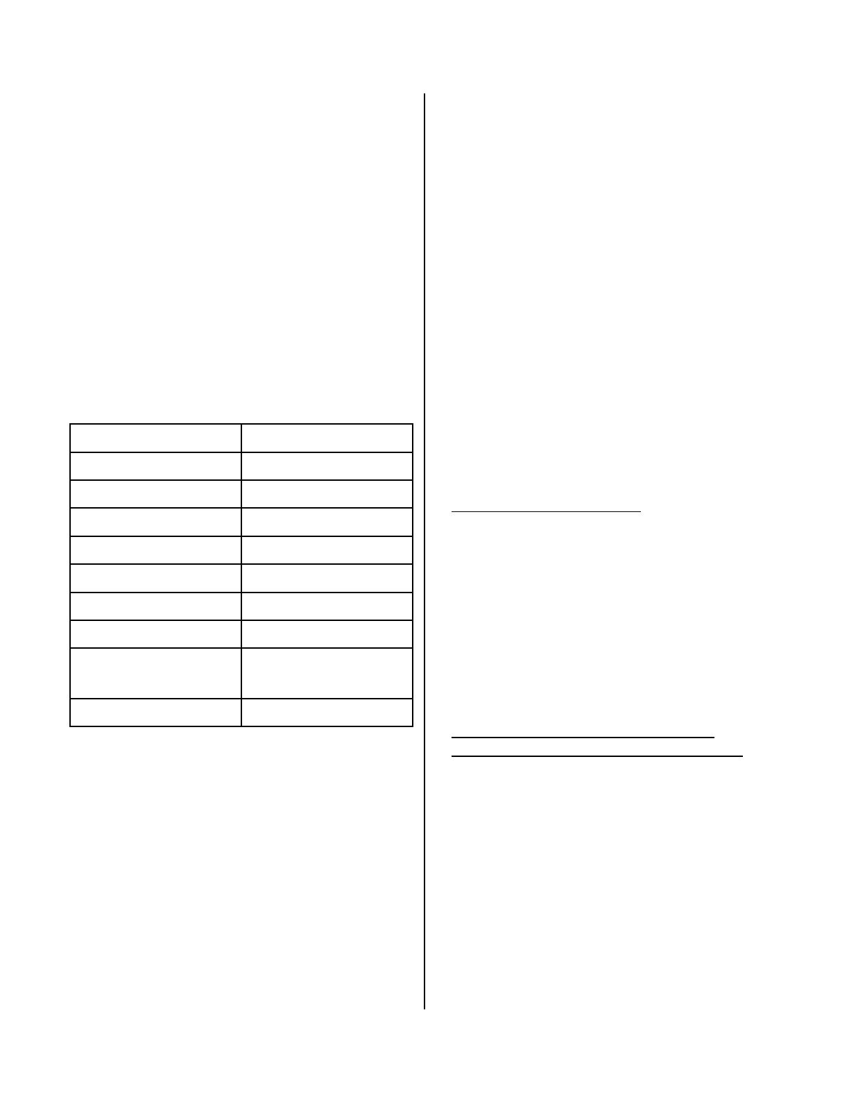
Waterthatcontainschemicalsexceedingthelevels
belowaectanddamagetheheatexchanger.
Replacementoftheheatexchangerduetowater
qualitydamageisnotcoveredbythewarranty.
MaximumLevel
TotalHardness Upto200mg/L
Alumin
um* Upto0.2mg/L
Chlorides* Upto250mg/L
Copper* Upto1.0mg/L
Iron* Upto0.3mg/L
Manganese* Upto0.05mg/L
pH* 6.5to8.5
TDS(TotalDissolved
Solids)*
Upto500mg/L
Zinc* Upto5mg/L
DetermineInstallaonLoc a on
Environment
Airsurroundingthewaterheater,venng,andvent
terminaon(s)isusedforcombusonandmustbe
freeofanycompoundsthatcausecorrosionof
internalcomponents.Theseincludecorrosive
compoundsthatarefoundinaerosolsprays,
detergents,bleaches,cleaningsolvents,oilbased
paints/varnishes,andrefrigerants.Theairinbeau
ty
shops,drycleaningstores,photoprocessinglabs,and
storageareasforpoolsuppliesoencontainsthese
compounds.Thereforeitisrecommendedthat
outdoormodelsbeusedfortheselocaonswhere
possible.
Thewaterheater,venng,andventterminaon(s)
shouldnotbeinstalledinanyareaswheretheairmay
containth
esecorrosivecompounds.Ifitisnecessary
forawaterheatertobelocatedinareaswhichmay
containcorrosivecompounds,thefollowing
instruconsarestronglyrecommended.
IMPORTANTCONSIDERATIONSFOR:
Indoor/InternalWaterHeaters
DONOTInstallinareaswhereairforcombuson
canbecontaminatedwithchemicals.
Beforeinstallaon,considerwhereairhasthe
abilitytotravelwithinthebuildingtothewater
heater.
Wherepossible,installthewaterheaterina
sealedclosetsothatitisprotectedfromthe
potenalofcontaminatedindoorair.
Chemicalsthatarecorrosiveinnatureshouldnot
bestoredorusednearthewaterheater.
Outdoor/ExternalWaterHeatersandVent
TerminaonsofIndoor/InternalWaterHeaters
Installthewaterheaterasfarawayaspossible
fromexhaustventhoods.
Installasfarawayaspossiblefromairinlet
vents.Corrosivefumesmaybereleasedthrough
theseventswhenairisnotbeingbroughtin
throughthem.
Chemicalsthatarecorrosiveinnatureshouldnot
bestoredorusednearthewaterheaterorvent
terminaon.
Damageandrepairduetocorrosivecompoundsin
theairisnotcoveredbywarranty.
WaterQuality
*Source:Part143NaonalSecondaryDrinkingWater
Regulaons
Ifyouliveinanareathatisknowntohavehardwater
orthatcausesscalebuildupyoumusttreatyour
waterand/orushtheheatexchangerregularly.
Whenscalebuildupintheheatexchangerbeginsto
aecttheper
formanceofthewaterheater,a
diagnosccode“LC”willdisplay.Flushtheheat
exchangertopreventdamagetoit.Scalebuildupis
causedbyhardwatersetatahightemperature.
Youmustensurethatclearanceswillbemetandthat
theventlengthwillbewithinrequiredli
mits.
Considertheinstallaonenvironment,waterquality,
andneedforfreezeprotecon.Requirementsforthe
gasline,waterlines,electricalconnecon,and
condensatedisposalcanbefoundintheirrespecve
installaonseconsofthismanual.
JS180F/JS199F 7
VentTerminaonClearances
INSIDE
CORNER DETAIL
FIXED
CLOSED
OPERABLE
FIXED
CLOSED
OPERABLE
B
B
B
A
J
B
M
C
F
B
B
E
D
L
G
A
H
K
I
[1] Aventshallnotterminatedirectlyaboveasidewalkorpaveddriveway
thatislocatedbetweentwosinglefamilydwellingsandservesboth
dwellings.
[2] Permiedonlyifveranda,porch,deck,orbalconyisfullyopenona
minimumoftwosidesbeneaththeoor.
ForclearancesnotspeciedinANSI Z223.1/NFPA 54,clearancesarein
accordancewithlocalinstallaoncodesandtherequirementsofthegas
supplier.
Clearancetooppositewallis24inches(60cm).
X
V
AIRSUPPLYINLET
VENTTERMINAL
AREAWHERETERMINAL
ISNOTPERMITTTED
Ref
Descripon
USInstallaons
A
Clearanceabovegrade(includingancipatedsnowline),veranda,
porch,deck,orbalcony
12inches(30cm)
B Clearancetowindowordoorthatmaybeopened 12inches(30cm)
C Clearancetopermanentlyclosedwindow *
D
Vercalclearancetovenlatedsot,loc
atedabovetheterminalwithin
ahorizontaldistanceof2feet(61cm)fromthecenterlineofthe
terminal
*
E Clearancetounvenlatedsot *
F Clearancetooutsidecorner *
G Clearancetoinsidecorner *
H
Clearancetoeachsideofcenterlineextendedabovem
eter/regulator
assembly
*
I Clearancetoserviceregulatorventoutlet *
J
Clearancetononmechanicalairsupplyinlettobuildingorthe
combusonairinlettoanyotherappliance
12inches(30cm)
K Clearancetoamechanicalairsupplyinlet
3feet(91cm)aboveifwithin10
feet(3m)hor
izontally
L
Clearanceabovepavedsidewalkorpaveddrivewaylocatedonpublic
property
*
M Clearanceunderveranda,porch,deck,orbalcony *
Youmustinstallaventterminaontobringincombusonairandexpelexhaust.
SNOW
TERMINATION
Clearance in
Ref. A also
applies to
anticipated
snow line
8 JS180F/JS199F
24"
V
Checkonwhetherlocalcodessupersedetheseclearances.
Avoidterminaonlocaonsnearadryervent.
Avoidterminaonlocaonsnearcommercialcookingexhaust.
Youmustinstallaventterminaonatleast12inchesfromtheground
60"
V
V
(1.52m)between
terminalsat
dierentlevels
12"
12"
36"
INSIDE
CORNER
VV
(0.91m)tovenlatedor
unvenlatedsotoreve
vent;ortoadeckorporch
(0.30m)toan
insidecorner
(0.30m)between
terminalsatsame
level
(0.61m)towallorparapet
(0.30m)between
terminalsatsame
level
12"
V V
(1.52m)vercally
betweenterminals
V
60"
V
AddionalClearances
JS180F/JS199F 9
UnitClearances
toCombusbles
inches(mm)
toNon
Combusbles
inches(mm)
TopofHeater 6*(152) 2*(51)
BackofHeater 0(zero) 0(zero)
FrontofHeater 6(152) 6(152)
SidesofHeater 2(51) 1/2(13)
Ground/Boom 12(305) 12(305)
Vent 0(zero) 0(zero)
*0inchesfromventcomponentsandcondensate
drainline.
Theclearanceforservicingis24inchesinfrontofthe
waterheater.
Forclosetinstallaon,clearanceis6inches(152mm
fromthefront.
MaximumVentLength
1. Determinethenumberof90degreeelbowsin
theventsystem.(Two45degreeelbowscountas
one90degreeelbow.)
2. Refertothetabletondthemaximumvent
lengthbasedonthenumberofelbows.
3. AdjustswitchNo.1intheSW1DIPswitchif
requiredbytheapplicablenote.
1 Ifthelengthisgreaterthan21(6.4m)then
moveswitchNo.1(SW1)toOFF.
2 Ifthelengthisgreaterthan15(4.6m)then
moveswitchNo.1(SW1)toOFF.
3 Ifthelengthisgreaterthan9(2.7m)thenmove
switchNo.1(SW1)toOF
F.
4MoveswitchNo.1(SW1)toOFF.
Example: Ifyouhaveoneelbowthenyourmaximum
ventlengthis35feet(10.7m).Ifyour
actuallengthisgreaterthan15(4.6m)
thenmoveswitchno.1(SW1)toOFF.
Numberof
90°Elbows
Maxim
umventlength
0 41(12.5m)1
1 35(10.7m)2
2 29(8.8m)3
3 23(7.0m)4
4 17(5.2m)4
5 11(3.4m)4
6 5(1.5m)4
Ifyouhavealongerventlength(seeabove),switch
No.1isrequiredtobeintheOFFposion.This
ensuresthewaterheaterwillrunproperly.Blocked
uediagnosccodesandshutdowns mayresultif
switchNo.1isnotinthecorrectposion.Onthe

JSN199FandJSP199F,themaximumwaterow
capacitywillbereducedbyabout10%whenswitch
no.1isOFF.
NOTICE
to side
to front
to top
to floor/ground
10 JS180F/JS199F
FreezeProtecon
Makesurethatincaseoffreezingweatherthatthe
waterheateranditswaterlinesareprotectedto
preventfreezing.Damageduetofreezingisnot
coveredbythewarranty.
Lossoffreezeproteconmayresultinwaterdamage
fromaburstheatexchangerorwaterlines.
Withelectricalpowersupplied,thewaterheat
erwill
notfreezewhentheoutsideairtemperatureisascol d
as–22°F(30°C)forindoormodelsorisascoldas–4°
F(20°C)foroutdoormodels,whenprotectedfrom
directwindexposure.Becauseofthe“windchill”
eect,anywindorcirculaonoftheairontheunit
willreduceitsabilitytofreezeprotect.
Theunitmaybedrainedmanually.However,itis
highlyrecommendedthat:
draindownsolenoidvalvesareinstalledthatwill
automacallydraintheunitifpowerislost.
Theseareavailableinakit,JA105.
asurgeprotectorwithterminalsisinstalledwhich
allowsthesolenoidvalvestooperateiftheunitis
disabledduetoadiagnos ccode.Thisis
availableasJA106.
Inaddion,thesolenoidvalvesshouldbeconnected
electricallytoasurgeprotectorwithterminals.This
allowsthesolenoidvalvestooperateifthewa
ter
heaterisdisabledduetoadiagnosccode.
Thefreezeproteconfeatureswillnotpreventthe
externalpipingfromfreezing.Itisrecommendedthat
hotandcoldwaterpipesareinsulated.Pipecover
enclosuresmaybepackedwithinsulaonforadded
freezeprotecon.
Intheeventofapowerfa
ilureattemperaturesbelow
freezingthewaterheatershouldbedra inedofall
watertopreventfreezingdamage.
JS180F/JS199F 11
MounttoWall
wallinstallaon
brackets
1. Idenfytheinstallaonlocaonandconrmthat
theinstallaonwillmeetallrequiredclearances.
2. Securelyaachthewaterheatertothewall
usinganyoftheholesinthewallinstallaon
bracketswhichareatthetopandboomofthe
waterhea
ter.Ensurethattheaachment
strengthissucienttosupporttheweight.
Refertotheweightofthewaterheaterinthe
Specicaonssecon.
NOTE:Thewaterheatershouldbeinstalledinan
uprightposion.Donotinstallupsidedownoronits
side.
ChecklisttoDetermineInstallaon
Locaon
□Thewaterheaterisnotexposedtocorrosive
compoundsintheair.
□Thewaterheaterlocaoncomplieswiththe
clearances.
□Theplannedvenngwillnotexceedthe
maximumlengthforthenumberofelbowsused.
□Theplannedvenngterminaon/airintake
locaonmeetstheclearances.
□Thewatersupplydoesnot containchemicalsor
exceedtotalhardnessthatwilldamagetheheat
exchanger.
Astandard3prong120VAC,60Hzproperly
groundedwalloutletorother120VAC,60Hz
sourceisavailable.
□VerifythatswitchNo.1intheSW1DIPswitchhas
beenadjustedforventlengthifnecessary.Refer
tothesecononMaximumVentLength.
□Theinstallaonmustconformwithlocalcodesor,
intheabsenceoflocalcodes,withtheNaonal
Fuel Gas Code, ANSI Z223.1/NFPA 54.Ifinstalled
inamanufacturedhome,theinstallaonmust
conformwiththeManufactured Home
Construcon and Safety Standard, Title 24 CFR,
Part 3280.
RemovetheFrontPanel
1. Pressthetopandboomofeachsidecoverand
pullthesidecoverawayfromtheproduct.
2. Removethe4screwsaachingthepaneltothe
waterheater.
12 JS180F/JS199F
Manufacturer Product Telephone Fax Contact
Ubbink RoluxVentSystem 8888359320 6788291666 www.jacuzzi.com/tankless
HeatFab SafTVentSCsystem
MetalFab Corr/GuardVent/AirIntake
System
8007720739
8008352830
4138634803
3169432717
custsvc@heatfab.com,
www.heaab.com
www.metalfabinc.
com
ListedandTestedVentProductsforJSN180F,JSP180F,J SN199F,JSP199F
InstallaonofVenng
Installthecorrectvenngforyourmodelaccordingtothevenngmanufacturer’sinstruconsandtheguide
linesbelow.
VenngGuidelines
DONOT
Donotcombineventcomponentsfromdierent
manufacturers.
Ventdiametermustnotbereduced.
Donotconnectthevenngsystemwithan
exisngventorchimney.
Donotcommonventwiththeventpipeofany
otherwaterheaterorappliance.
MUSTDO
Thiswaterheaterisadirectventwaterheaterand
thereforeisceredandlistedwiththevent
system.Youmustuseventcomponentsthatare
ceredandlistedwiththewaterheatermodel.
Theventsystemmustventdirectlytotheoutside
ofthebuildinganduseoutsideairforcombuson.
Avoiddipsorsagsinhorizontalventrunsby
installingsupportspertheventmanufacturer’s
instrucons.
Supporthorizontalventrunseveryfourfeetand
allvercalventrunseverysixfeetorin
accordancewithlocalcodes.
Venngshouldbeasdirectaspossiblewitha
minimumnumberofpipengs.
Ventconneconsmustbermlypressedtogether
sothatthegasketsformanairghtseal.
Theventpiececonnectedtothewaterheater
mustbesecuredwithoneselftappingscrew.
INFORMATION
Refertotheinstruconsoftheventsystem
manufacturerforcomponentassembly
instrucons.
Iftheventsystemistobeenclosed,itissuggested
thatthedesignoftheenclosureshallpermit
inspeconoftheventsystem.Thedesignofsuch
enclosureshallbedeemedacceptablebythe
installerorthelocalinspector.
NOTICE
Ifitbecomesnecessarytoaccessanenclosedvent
systemforserviceorrepairs,Jacuzziisnot
responsibleforanycostsordiculesinaccessing
theventsystem.Thewarrantydoesnotcover
obtainingaccesstoaventsysteminanenclosed
environment.
JS180F/JS199F 13
FlueInstallaon
Condensate
Trap
VercalTerminaon
(condensatecollectormustbeusedinallinstallaons)
3in(75mm)
minimum
3in(75mm)
minimum
HorizontalTerminaonusingthe
CondensateCollector
3in(75mm)
minimum
Condensate
Trap
Toadjustthecondensatecollectorposionorto
replacethefemaleventtopwithamaleventtop:
1. Loosenthe4screwsattherearbracket
2. Slidethebracketawayfromthefemaleventtop.
3. Removethe4screwsaachingthefemaleventtop
tothewaterheater.
4. Liupthefemaleventtopandreposionasdesire
d
(orreplacewithamaleventtop).
5. Installthe4screwsattheventtopandghtenthe4
screwsatthebracket.
Securetherstventcomponenttothewaterheater
withoneselftappingscrewattheholelocatedabove
thecondensatecollector.
Bracket
CondensateCollector
SecuringScrew
HorizontalTerminaonwithoutusingtheCondensateCollector
MaximumHeight*
5feet(1.52m)
Regionsofcoldclimatewillcreatemore
condensateintheventsystem.The
condensatecollectorshouldbeusedin
coldclimates.
Ifmorethanoneelbowisusedinthe
vercalseconthecondensatecollector
mustbeused.
*Thecondensatecollectormustbeusedin
horizontalterminaonsifavercalrisein
theventsystemexceeds5.
Ifthecondensatecollectorisnotused,thedrainpipemust
becappedtopreventexhaustgasesandcondensatefrom
enteringthebuilding.Thecapissuppliedontheappliance.
WARNING
Installthevenngterminaonaccordingtothediagramsandinstruconsbelow.
14 JS180F/JS199F
InstallaonofCondensateTrap
Condensateformaoncanoccurinhigheciency
directventappliances.Withoutproperdrainage
condensatewilldamagetheheatexchanger.
Topreventcondensatedamagefollowthese
instrucons.
DONOT
Donotallowcondensatetoenterthewater
heater.
DonotusePVC,CPVC,ABSorgalvanizedmaterial
toventthisappliance.
Donotconnectthecon densatedrainpipedirectly
totherainsewer.
Donotconnectthecon densatedrainlinewithan
aircondioningevaporatorcoildrain.
MUSTDO
Useonlyventthatisapprovedandidenedas
acceptableforyourparcularmodel.
Forvercalterminaons,installacondensatedrain
andtrapascloseaspossibletotheappliance.
Slopethevenngtowardtheapplianceaccording
totheventmanufacturersinstallaoninstrucons.
Allcondensatemustdrainandbedisposedof
accordingtolocalcodes.
UseonlyPVCorCPVCpipefortheconde nsate
drainline.
Thecondensate drainpipe(alongitsenrelength)
mustbeatleastthesamediameterasthedrain
line,(3/8inchNPT).
Theend ofthecondensatedrainpipeshouldbe
opentotheatmosphere.Theendshouldnotbe
underwaterorothersubstances.
Tominimizefreezingofthecondensate,runthe
condensatedrainlinethroughaninteriorwallor
betweeninsulaonandaninteriorwall.
Thecondensate collectorshouldbeusedforall
hydronicheangapplicaons.
ChecklistforVenngand
Condensate
□Verifyproperclearancesaroundtheventsandair
intakes.
□Ensureyouhaveusedthecorrectvenng
productsforthemodelinstalledandthatyou
havecompletelyfollowedthevenng
manufacturer’sinstallaoninstruconsandthese
installaoninstrucons.
□Verifythattheventpipehasadownwardslopeor
gradetotheoutsideof1/4inchperfoot(1.2°)
ORiftheventpipeisslopedtowardthewater
heater(assomelocalcodesrequire),thata
condensatecollectorisinstalledtoallow
condensaontodrainawayfromthewat
er
heatertoaproperdrainsource.
□Verifythatcondensatewillnotbeallowedto
drainbackintothewaterheater.
□Verifythattheventsystemdoesnotexceedthe
maximumlengthforthenumberofelbowsused.
INFORMATION
Signaturewaterheatershaveanintegrated
condensatecollector.
Acondensate trapis available, JSV016.
Regionsofcoldclimatewillcreatemore
condensateintheventsystem.Thecondensate
collectorshouldbeusedincoldclimates.
Thecondensate drainpipeshouldbeasshortas
possibleandhaveadownwardpitch.
JS180F/JS199F 15
InstallaonofPlumbing
Amanualwatercontrolvalvemustbeplacedinthe
waterinletconnecontothewaterheaterbeforeitis
connectedtothewaterline.Unionsmaybeusedon
boththehotandcoldwaterlinesforfutureservicing
anddisconneconoftheunit.
DONOT
Donotintroducetoxicchemicalssuchasthose
usedforboilerwatertreatmenttothepotable
waterusedforspaceheang.
MUSTDO
Thepiping(includingsolderingmaterial s)and
componentsconnectedtothisappliancemustbe
approvedforuseinpotablewatersystems.
Purgethewaterlinetoremovealldebrisandair.
Debriswilldamagethewaterheater.
Iftheappliancewillbeusedasapotablewater
source,itmustnotbeconnectedtoasystemthat
waspreviouslyusedwithanonpotablewater
heangappliance.
Ensurethatthewaterlteronthewaterheateris
cleanandinstalled.
PipingRequirements
PressureReliefValveRequirements
Installapressurereliefvalveaccordingtothese
instrucons.
Anapprovedpressurereliefvalveisrequiredbythe
American Naonal Standard (ANSI Z21.10.3) forall
waterheangsystems,andshallbeaccessiblefor
servicing.
DONOT
Donotplugthereliefvalveanddonotinstallany
reducingngsorotherrestriconsintherelief
line.Therelieflineshouldallowforcomplete
drainageofthevalveandtheline.
Donotplaceanyothertypevalveorshutoff
devicebetweenthereliefvalveandthewater
heater.
MUSTDO
Thereliefvalvemustcomplywiththestandardfor
Relief Valves and Automac Gas Shuto Devices for
Hot Water Supply Systems ANSI Z21.22and/orthe
standardTemperature, Pressure, Temperature and
Pressure Relief Valves and Vacuum Relief Valves,
CAN14.4.
Thereliefvalvemustberatedupto150psiandto
atleastthemaximumBTU/hroftheappliance.
Thedischargefromthepressurereliefvalveshould
bepipedtothegroundorintoadrainsystemto
preventexposureorpossibleburnhazardsto
humansorotherplantoranimallife.Followlocal
codes.Waterdischargedfromthereliefvalve
couldcausesevereburnsinstantly,scalds,or
death.
Thepressurereliefvalvemustbemanually
operatedonceayeartocheckforcorrect
operaon.
Thereliefvalveshouldbeaddedtothehotwater
outletlineandnearthehotwateroutletaccording
tothemanufacturer’sinstrucons.DONOTplace
anyothertypevalveorshutoffdevicebetween
thereliefvalveandthewaterheater.
INFORMATION
Ifareliefvalvedischargesperiodically,thismaybe
duetothermalexpansioninaclosedwatersupply
system.Contactthewatersupplierorlocal
plumbinginspectoron howtocorrectthis
situaon.Donotplugthereliefvalve.
TheAmerican Naonal Standard (ANSI Z21.10.3)
doesnotrequireacombinaontemperatureand
pressurereliefvalveforthisappliance.However,
localcodesmayrequireacombinaon
temperatureandpressurereliefvalve.
IsolaonValves
Jacuzzirecommendsinstallaonofisolaonvalveson
thecoldandhotwaterlines.Isolaonvalvesprovide
theabilitytoisolatethewaterheaterfromthe
structure’splumbingandallowquickaccesstoush
theheatexchanger.
16 JS180F/JS199F
PipingDiagramforBasicInstallaon
G
a
s
S
u
p
p
ly
3
/
4
"
C
o
ld
W
a
t
e
r
S
u
p
p
ly
L
in
e
3/4" HotWater Supply Line
Rinnai
Water Heater
Rinnai
Equipment List
Rinnai
Water Heaters
RIK-KIT (Optional)
(3/4" Fittings Include:
2 Unions, 2 Ball Valves,
2Drain Valves and
1 Pressure Relief Valve.)
QTY
1
1
3
/
4
"
G
a
s
C
o
n
n
e
c
t
io
n
For Building Fixtures
Pressure Relief Valve
3/4" Ball Valve
3/4" Union
Check Valve
S
Pressure Regulator
Circulating Pump
Solenoid Valve
Boiler Drain Valve
KEY
This is not an engineered drawing. It is intended only as a guide and not
as a replacement for professionally engineered project drawings. This
drawing is not intended to describe a complete system. It is up to the
contractor/engineer to determine the necessary components and
configuration of the particular system being installed. This drawing does
not imply compliance with local building code requirements. It is the
responsibility of the contractor/engineer to ensure installation is in
accordance with all local building codes. Confer with local building
officials before installation.
JS180F/JS199F 17
InstallaonofGasSupply
MUSTDO
Amanualgascontrolvalvemustbeplacedinthe
gassupplylinetothewaterheater.Aunioncanbe
usedontheconneconabovetheshutoffvalve
forthefutureservicingordisconneconofthe
unit.
Checkthetypeofgasandthegasinletpressure
beforeconnecngthewaterheater.Ifthewater
heaterisnotofthegastypethatthebuildingis
suppliedwith,DONOTconnectthewaterheater.
Contactthedealerfortheproperunittomatchthe
gastype.
Checkthegassupplypressureimmediately
upstreamatalocaonprovidedbythegas
company.Suppliedgaspressuremustbewithin
thelimitsshownintheSpecicaonsseconwith
allgasappliancesoperang.
Beforeplacingtheapplianceinoperaonalljoints
includingtheheatermust becheckedforgas
ghtnessbymeansofleakdetectorsoluon,soap
andwater,oranequivalentnonammable
soluon,asapplicable.(Sincesomeleaktest
soluons,includingsoapandwater,maycause
corrosionorstresscrack
ing,thepipingshallbe
rinsedwithwateraertesng,unlessithasbeen
determinedthattheleaktestsoluonisnon
corrosive.)
Useapprovedconnectorstoconnecttheunitto
thegasline.Purgethegaslineofanydebris
beforeconnecontothewaterheater.
ConnectWaterHeatertoWaterSupply
Waterconneconstothetanklesswaterheater
shouldfollowallstateandlocalplumbingcodes.
Ifthisisastandardinstallaon,refertothePiping
DiagramforBasicInstallaon.
1. Plumbwatersupplytothetanklesswaterheater
onthe3/4”MNPTconneconattheboomof
theuni
tmarked“WaterInlet”,whichisthecold
watersupply.
2. Plumbthebuildinghotwatersupplytothe3/4”
MSPTconneconmarked“WaterOutlet”,which
isthehotwatersupply.
Ifapipecoverwillbeinstalled,makesurewaterlines
tothewaterheatert.
GeneralInstrucons
ChecklistforPlumbing
□Ensurethathotandcoldwaterlinesarenot
crossedtotheunitandareleakfree.
□Ensurethatapressurereliefvalveisinstalledwith
arangthatexceedstheBTUinputofthewater
heatermodel.Refertotherangplateonthe
sideofthewaterheaterforBTUinput.
□Cleantheinletwaterlterbyclosingthecoldand
hotwaterinletisolaon(shuto)valves.Puta
bucketunderthelterattheboomofthewater
heatertocatchanywaterthatiscontainedinside
theunit.Unscrewthewaterlter.Rinsethe
ltertoremo
veanydebris.Installthelterand
opentheisolaonvalves.
WARNING
1. Ifyouarenotknowledgeableorqualiedto
installgaslinesorconnecons,thencontacta
licensedprofessionaltoinstallthegassupply.
2. Turnoff120vpowersupply.
3. Turnoffthegas.
4. Gasisammable.Donotsmokeorprovideother
ignionsourceswhileworkingwithgas.
5. Donottur
nonthewaterheaterorgasunlall
fumesaregone.
18 JS180F/JS199F
Sizethegaspipe
Thegassupplymustbeca pableofhandlingtheenre
gasloadatthelocaon.Gaslinesizingisbasedon
gastype,thepressuredropinthesystem,thegas
pressuresupplied,andgaslinetype.Forgaspipesiz
ingintheUnitedStates,refertotheNaonal F
uel Gas
Code, NFPA 54.Thebelowinformaonisprovidedas
anexample.Theappropriatetablefromtheapplica
blecodemustbeused .
1. Forsometables,youwillneedtodeterminethe
cubicfeetperhourofgasrequiredbydividingthe
gasinputbytheheangvalueofthegas
(availablefromthelocalgascompany).Thegas
inputneedstoincludeallgasproductsatthelo
caonandthemaxi
mumBTUusageatfullload
whenallgasproductsareinuse.
2. Usethetableforyourgastypeandpipetypeto
ndthepipesizerequired.Thepipesizemustbe
abletoprovidetherequiredcubicfeetperhour
ofgasortherequiredBTU/hour.
Examp
le:
Theheangvalueofnaturalgasforyourlocaonis
1000BTU/FT
3
.ThegasinputoftheJSN199Fis
199,000BTU/HR.Addionalappliancesattheloca
onrequire65,000BTU/hr.Thereforethecubicfeet
perhour=(199,000+65,000)/1000=264FT
3
/HR.If
thepipelengthis10feetthenthe3/4inchpipesizeis
capableofsupplying264FT
3
/HRofnaturalgas.
GasInputofallgasproducts(BTU/HR)
HeangValueofGas(BTU/FT
3
)
CubicFeet
perHour=
(CFH)
Anycompoundusedonthethreadedjointofthe
gaspipingshallbeatypewhichresiststheacon
ofliqueedpetroleumgas(propane/LPG).
Thegassupplylineshallbegasght,sized,andso
installedastoprovideasupplyofgassucientto
meetthemaximumdemandoftheheaterandall
othergasconsumingappliancesatthelocaon
withoutlossofpressure.
INFORMATION
Refertoanapprovedpipesizingchartifindoubt
aboutthesizeofthegasline.
Length
PipeSize(inches)
3/4 1 11/4 11/2
10 273 514 1060 1580
20 188 353 726 1090
30 151 284 583 873
40 129 243 499 747
50 114 215 442 662
60 104 195 400 600
70 95 179 368 552
80 89 167 343 514
90 83 157 322 482
100 79 148 304 455
PipeSizingTable‐NaturalGas
InletPressure: lessthan2psi(55inchesW.C.)
PressureDrop: 0.3inchesW.C.
SpecicGravity: 0.60
Schedule40MetallicPipe
cubicfeetperhour
Length
PipeSize(inches)
1/2 3/4 1 11/4
10 291 608 1150 2350
20 200 418 787 1620
30 160 336 632 1300
40 137 287 541 1110
50 122 255 480 985
60 110 231 434 892
80 101 212 400 821
100 94 197 372 763
PipeSizingTable‐PropaneGas
InletPressure: 11.0inchesW.C.
PressureDrop: 0.5inchesW.C.
SpecicGravity: 1.50
Schedule40MetallicPipe
CapacityinThousandsofBTUperHour
JS180F/JS199F 19
ConnectElectricity
Thewaterheaterrequires120VAC,60Hzpowerfrom
aproperlygroundedcircuit.
Ifusingthe5footlongpowercord,plugitintoa
standard3prong120VAC,60Hzproperlygrounded
walloutlet.
ThewiringdiagramislocatedontheTechnicalSheet
aachedtotheinsideofthefrontcove
r.
WARNING
Donotuseanextensioncordoranadapterplugwith
thisappliance.
Thewaterheatermustbeelectricallygroundedin
accordancewithlocalcodesandordinancesor,inthe
absenceoflocalcodes,inaccordancewiththe
NaonalElectricalCode,ANSI/NFPANo.70.
Thiswaterheaterisequippedwithathr
eeprong
(grounding)plugforyourproteconagainstshock
hazardandshouldbepluggeddirectlyintoaproperly
groundedthreeprongreceptacle.Donotcutor
removethegroundingterminalfromthisplug.
ChecklistforGasandElectricity
□Amanualgascontrolvalveisplacedinthegas
linetothewaterheater.
□Checkthegaslinesandconneconsforleaks.
□Conrmthatthegasinletpressureiswithin
limits.
□Conrmthatthewaterheaterisratedforthegas
typesupplied.
□Conrmthattheelectricityissuppliedfrom120
VAC,60Hzpowersourceandisinaproperly
groundedcircuit.
□Anextensioncordoranadapterplughasnot
beenusedwiththewaterheater.
AdjustforHighAltude
OntheDIPswitch,setswitches2and3tothevalues
shownintablebelowforyouraltude.Thedefault
sengfortheapplianceis02000(0610m)with
switchesNo.2andNo.3intheOFFposion.
WhentheDIPswitchisadjusted,itisnotnecessaryto
adjustthegaspressuresengforhi
ghaltude.
Altude
Switch
No.2
Switch
No.3
02000(0610m) OFF OFF
20015200(6101585m) OFF ON
52017700(15852347m) ON OFF
770110200(23473109m) ON ON
20 JS180F/JS199F
InstallaonofTemperature
Controller
ControllerLocaon
MounngtheController
CableLengthsandSizes
Thecontrollershouldbeoutofreachofsmall
children.
Avoidlocaonswherethecontrollermaybecome
hot(neartheovenorradiantheater).
Avoidlocaonsindirectsunlight.Thedigital
displaymaybediculttoreadindirectsunlight.
Avoidlocaonswherethetemperaturecontroller
couldbesplashedwithliquids.
Indoormodelshavetheircontrollerbuiltintothe
frontpanel.Addionalcontrollerscanbeinstalled.
Thecableforthetemperat urecontrollershouldbea
nonpolarizedtwocorecablewithaminimumgauge
of22AWG.Themaximumca
blelengthfromeach
controllertothewaterheaterdependsonthetotal
numberofwiredcontrollersconnectedtothewater
heater.
NumberofWired
Controllers
MaximumCableLengthforeach
ControllertoWaterHeater
1 328(100m)
2 164(50m)
3or4 65(20m)
Turnthepowero.Donotaempttoconnectthe
temperaturecontrollerswiththepoweron.Although
thecontrollerisalowvoltagedevice,th ereis120volt
potenalnexttothetemperaturecontroller
conneconsinsidetheunit.
Donotconnectthetemperaturecontrollertothe
120VACterminalsprovide
dfortheoponalsolenoid
drainvalves.
WARNING
1. Makethreeholesinthewallasshown.
2. Runthecablebetweenthecontrollerandthe
waterheaterorthecontrollerandanother
controller.
3. Removethefaceplatefromthetemperature
controllerusingascrewdriver.
4. Connectthecabletothetemperaturecontroller.
5. Mountthecontrollertoth
ewallusingtheholes
drilledinstep1.
6. Disconnectthepowerfromthewaterheater.
7. RemovetheplasccoverfromthePCBand
electricalconnecons.
8. Threadthecablethroughtheaccessholeatthe
baseoftheunitandconnectthewirestothe
controllerter
minalsontherighthandsideboom
ofthePCB.
9. Securethecontrollercableusingtheclamp
provided.
10. ReplaceplasccoveroverPCBandthenreplace
thecoverofthewaterheater.
Outline of Remote
securing screw
1-21/32"
3-5/16
"
securing screw
wiring hole
  • Page 1 1
  • Page 2 2
  • Page 3 3
  • Page 4 4
  • Page 5 5
  • Page 6 6
  • Page 7 7
  • Page 8 8
  • Page 9 9
  • Page 10 10
  • Page 11 11
  • Page 12 12
  • Page 13 13
  • Page 14 14
  • Page 15 15
  • Page 16 16
  • Page 17 17
  • Page 18 18
  • Page 19 19
  • Page 20 20
  • Page 21 21
  • Page 22 22
  • Page 23 23
  • Page 24 24
  • Page 25 25
  • Page 26 26
  • Page 27 27
  • Page 28 28
  • Page 29 29
  • Page 30 30
  • Page 31 31
  • Page 32 32
  • Page 33 33
  • Page 34 34
  • Page 35 35
  • Page 36 36
  • Page 37 37
  • Page 38 38
  • Page 39 39
  • Page 40 40
  • Page 41 41
  • Page 42 42
  • Page 43 43
  • Page 44 44
  • Page 45 45
  • Page 46 46
  • Page 47 47
  • Page 48 48
  • Page 49 49
  • Page 50 50
  • Page 51 51
  • Page 52 52
  • Page 53 53
  • Page 54 54
  • Page 55 55
  • Page 56 56
  • Page 57 57
  • Page 58 58
  • Page 59 59
  • Page 60 60
  • Page 61 61
  • Page 62 62
  • Page 63 63
  • Page 64 64
  • Page 65 65
  • Page 66 66
  • Page 67 67
  • Page 68 68
  • Page 69 69
  • Page 70 70
  • Page 71 71
  • Page 72 72
  • Page 73 73
  • Page 74 74
  • Page 75 75
  • Page 76 76
  • Page 77 77
  • Page 78 78
  • Page 79 79
  • Page 80 80
  • Page 81 81
  • Page 82 82
  • Page 83 83
  • Page 84 84

Jacuzzi J?SN180F Operating instructions

Category
Water heaters & boilers
Type
Operating instructions
This manual is also suitable for

Ask a question and I''ll find the answer in the document

Finding information in a document is now easier with AI

in other languages