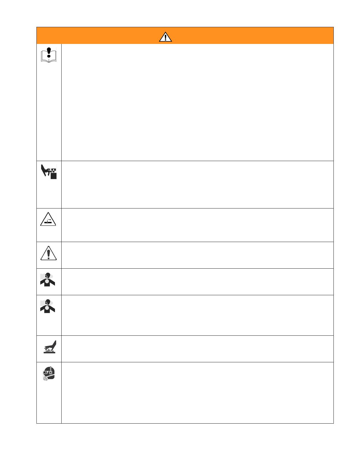
Graco 249318 User manual

Category
Paint Sprayer
Type
User manual
Graco Inc. P.O. Box 1441 Minneapolis, MN 55440-1441
Copyright 2006, Graco Inc. is registered to I.S. EN ISO 9001
- Use with Architectural Coatings, Paints, Roof Coatings
and Below Grade Coatings -
4000 psi (27.6 MPa, 275.8 bar) Maximum Working Pressure
Model: 249318, 249617, 253471, 253472
Related Manuals
Important Safety Instructions. Read all
warnings and instructions in this manual. Save
these instructions.
311279
311484
311485
311254
311283D
Repair
GH
833 Sprayers
Korean patent: 10-0647761
ti7107b
ENG
Warning
2 311283D
Warning
The following are general warning related to the safe setup, use, grounding, maintenance and repair of this equipment.
Additional, more specific warnings may be found throughout the body of this manual where applicable. Symbols ap-
pearing in the body of the manual refer to these general warnings. When these symbols appear throughout the man-
ual, refer back to these pages for a description of the specific hazard.
WARNING
FIRE AND EXPLOSION HAZARD
Flammable fumes, such as solvent and paint fumes, in work area can ignite or explode. To help prevent
fire and explosion:
Use equipment only in well ventilated area.
Do not fill fuel tank while engine is running or hot; shut off engine and let it cool. Fuel is flammable
and can ignite or explode if spilled on hot surface.
Eliminate all ignition sources; such as pilot lights, cigarettes, portable electric lamps, and plastic drop
cloths (potential static arc).
Keep work area free of debris, including solvent, rags and gasoline.
Do not plug or unplug power cords, or turn power or light switches on or off when flammable fumes
are present.
Ground all equipment in the work area. See Grounding instructions.
Use only grounded hoses.
Hold gun firmly to side of grounded pail when triggering into pail.
If there is static sparking or you feel a shock, stop operation immediately. Do not use equipment
until you identify and correct the problem.
Keep a working fire extinguisher in the work area.
SKIN INJECTION HAZARD
High-pressure fluid from gun, hose leaks, or ruptured components will pierce skin. This may look like just
a cut, but it is a serious injury that can result in amputation. Get immediate surgical treatment.
Do not point gun at anyone or at any part of the body.
Do not put your hand over the spray tip.
Do not stop or deflect leaks with your hand, body, glove, or rag.
Do not spray without tip guard and trigger guard installed.
Engage trigger lock when not spraying.
Follow Pressure Relief Procedure in this manual, when you stop spraying and before cleaning,
checking, or servicing equipment.
PRESSURIZED EQUIPMENT HAZARD
Fluid from the gun/dispense valve, leaks, or ruptured components can splash in the eyes or on skin and
cause serious injury.
Follow Pressure Relief Procedure in this manual, when you stop spraying and before cleaning,
checking, or servicing equipment.
Tighten all fluid connections before operating the equipment.
Check hoses, tubes, and couplings daily. Replace worn or damaged parts immediately.
RECOIL HAZARD
Brace yourself; gun may recoil when triggered and cause you to fall, which could cause serious injury.
Warning
311283D 3
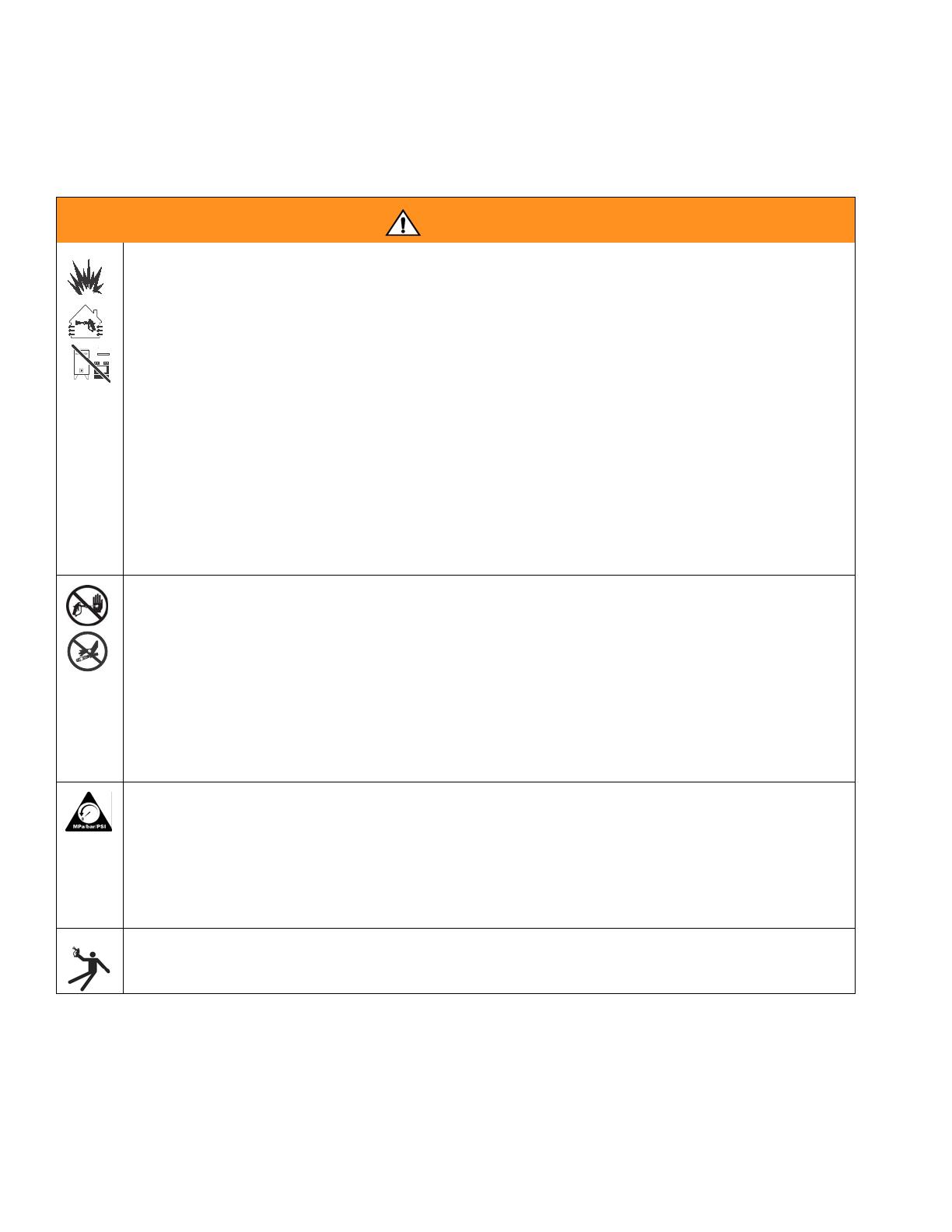
EQUIPMENT MISUSE HAZARD
Misuse can cause death or serious injury.
Do not operate the unit when fatigued or under the influence of drugs or alcohol.
Do not exceed the maximum working pressure or temperature rating of the lowest rated system
component. See Technical Data in all equipment manuals.
Use fluids and solvents that are compatible with equipment wetted parts. See Technical Data in all
equipment manuals. Read fluid and solvent manufacturer’s warnings. For complete information
about your material, request MSDS forms from distributor or retailer.
Check equipment daily. Repair or replace worn or damaged parts immediately with genuine Manu-
facturer’s replacement parts only.
Do not alter or modify equipment.
Use equipment only for its intended purpose. Call your distributor for information.
Route hoses and cables away from traffic areas, sharp edges, moving parts, and hot surfaces.
Do not kink or over bend hoses or use hoses to pull equipment.
Keep children and animals away from work area.
Comply with all applicable safety regulations.
MOVING PARTS HAZARD
Moving parts can pinch or amputate fingers and other body parts.
Keep clear of moving parts.
Do not operate equipment with protective guards or covers removed.
Pressurized equipment can start without warning. Before checking, moving, or servicing equipment,
follow the Pressure Relief Procedure in this manual. Disconnect power or air supply.
PRESSURIZED ALUMINUM PARTS HAZARD
Do not use 1,1,1-trichloroethane, methylene chloride, other halogenated hydrocarbon solvents or fluids
containing such solvents in pressurized aluminum equipment. Such use can cause serious chemical
reaction and equipment rupture, and result in death, serious injury, and property damage.
SUCTION HAZARD
Never place hands near the pump fluid inlet when pump is operating or pressurized. Powerful suction
could cause serious injury.
CARBON MONOXIDE HAZARD
Exhaust contains poisonous carbon monoxide, which is colorless and odorless. Breathing carbon
monoxide can cause death. Do not operate in an enclosed area.
TOXIC FLUID OR FUMES HAZARD
Toxic fluids or fumes can cause serious injury or death if splashed in the eyes or on skin, inhaled, or
swallowed.
Read MSDS’s to know the specific hazards of the fluids you are using.
Store hazardous fluid in approved containers, and dispose of it according to applicable guidelines.
BURN HAZARD
Equipment surfaces and fluid that’s heated can become very hot during operation. To avoid severe
burns, do not touch hot fluid or equipment. Wait until equipment/fluid has cooled completely.
PERSONAL PROTECTIVE EQUIPMENT
You must wear appropriate protective equipment when operating, servicing, or when in the operating
area of the equipment to help protect you from serious injury, including eye injury, inhalation of toxic
fumes, burns, and hearing loss. This equipment includes but is not limited to:
Protective eyewear
Clothing and respirator as recommended by the fluid and solvent manufacturer
•Gloves
Hearing protection
WARNING
Component Identification
4 311283D
Component Identification
,
ti7133b
ti7107b
3
2
4
1
6
7
5
9
11
10
ti7133
8
Ref Description
1 Hydraulic pump valve
2 Pressure control
3 Lock ring
4 Drain valve
5 Engine ON/OFF switch
6 Engine controls
7 Trigger lock
8 Serial number ID label
9 Lift locations
10 Suction holder
11 Hydraulic oil fill
Operation
311283D 5
Operation
Pressure Relief Procedure
1 Set pump valve OFF. Turn engine OFF.
2 Turn pressure to lowest setting. Trigger gun into pail to
relieve pressure.
3 Open prime valve (vertical).
If you suspect that the spray tip or hose is completely
clogged, or that pressure has not been fully relieved after
following the steps above, VERY SLOWLY, loosen tip
guard retaining nut or hose end coupling to relieve pres-
sure gradually, then loosen completely. Then clean tip
and hose.
General Repair Information
Install belt guard before operation of sprayer and
replace if damaged. Belt guard reduces risk of
pinching and loss of fingers.
To reduce risk of serious injury,:
Keep all screws, nuts, washers, etc. removed during
repair procedures. These parts usually are not pro-
vided with replacement kits.
Test repairs after problems are corrected.
If sprayer does not operate properly, review repair
procedure to verify you did it correctly. See Trouble-
shooting, page 7.
Do not touch moving parts with fingers or tools while
testing repair.
Grounding
Ground sprayer with grounding clamp to earth ground
for safe sprayer operation.
System pressure must be manually relieved to prevent
it from starting or spraying accidentally. Fluid under
high pressure can be injected into the skin and cause
serious injury. To reduce risk of injury from injection,
follow this procedure whenever you are instructed to
relieve pressure, stop spraying, service equipment or
install or clean spray tip. Read warnings, page 4.
TIA
Hydraulic system and engine may become very
hot during operation and could burn skin if
touched. Flammable materials spilled on hot, bare
motor could cause fire or explosion. Have belt
guard in place during operation to reduce risk of
pinching or loss of fingers.
Maintenance
6 311283D
Maintenance
For detailed engine maintenance and
specifications, refer to separate Honda
Engines Owner’s Manual, supplied.
Spark Plug:
Use BPR6ES (NGK) or W20EPR-U (NIPPON-
DENSO) plug, only.
Gap plug to 0.028 to 0.031 in. (0.7 to 0.8 mm).
Use spark plug wrench when installing and remov-
ing plug.
Frequency Procedure
Daily Check engine oil level and fill as necessary.
Daily Check hydraulic oil level and fill as necessary.
Daily Check hose for wear and damage.
Daily Check gun safety for proper operation.
Daily Check pressure drain valve for proper operation.
Daily Check and fill gas tank.
Daily Check that displacement pump is tight.
Daily Check level of TSL in displacement pump packing nut. Fill nut, if neces-
sary. Keep TSL in nut to help prevent fluid build up on piston rod and
premature wear of packings and pump corrosion.
After first 20 hours
of operation
Drain engine oil and refill with clean oil. Reference Honda Engines
Owner’s Manual for correct oil viscosity.
Weekly Remove engine air filter cover and clean element. Replace element, if
necessary. If operating in an unusually dusty environment; check filter
daily and replace, if necessary.
Replacement elements can be purchased from your local Honda dealer.
Weekly/Daily Remove and debris or media from hydraulic rod.
After each 100
hours of operation
Change engine oil. Reference Honda Engines Owner’s Manual for cor-
rect oil viscosity.
Semi-annually Check belt wear; replace if necessary.
Yearly or 2000
hours
Replace hydraulic oil and filter element with Graco ISO 46 Hydraulic Oil
169236; 5 gallon/20 liter or 207428; 1 gallon/3.8 liter) and filter element
287871.
Troubleshooting
311283D 7
Troubleshooting
PROBLEM CAUSE SOLUTION
Gas engine pulls hard (won't start) Hydraulic pressure is too high Turn hydraulic pressure knob coun-
terclockwise to lowest setting
Gas engine does not start Switch OFF, low oil, no gasoline Consult engine manual, supplied
Gas engine doesn't work properly Faulty engine Consult engine manual, supplied
Gas engine operates, but displace-
ment pump doesn't operate
Pump valve is OFF Set pump valve ON
Pressure setting too low Increase pressure
Displacement pump outlet filter (if
used) is dirty or clogged
Clean the filter
Tip or tip filter (if used) is clogged Remove tip and/or filter and clean
Hydraulic fluid too low Shut off sprayer. Add fluid*.
Belt worn, broken or off Replace belt.
Hydraulic pump worn or damaged Bring sprayer to Graco distributor for
repair
Dried paint seized paint pump rod Service pump. See manual 311485
Hydraulic motor not shifting Set pump valve OFF. Turn pressure
down. Turn engine OFF. Pry rod up or
down until hydraulic motor shifts.
Displacement pump operates, but
output is low on upstroke
Piston ball check not seating properly Service piston ball check. See man-
ual 311485
Piston packings worn or damaged Replace packings. See manual
311485
Displacement pump operates but
output is low on downstroke and/or
on both strokes
Piston packings worn or damaged Tighten packing nut or replace pack-
ings. See manual 311485
Intake valve ball check not seating
properly
Service intake valve ball check. See
manual 311485
Suction tube air leak
Paint leaks and runs over side of wet-
cup
Loose wet-cup Tighten wet-cup enough to stop leak-
age
Throat packings worn or damaged Replace packings. See manual
311485
Excessive leakage around hydraulic
motor piston rod wiper
Piston rod seal worn or damaged Replace these parts.
Fluid delivery is low Pressure setting too low Increase pressure
Displacement pump outlet filter (if
used) is dirty or clogged
Clean filter
Intake line to pump inlet is not tight Tighten
Hydraulic motor is worn or damaged Bring sprayer to Graco distributor for
repair
Large pressure drop in fluid hose Use larger diameter or shorter hose
Troubleshooting
8 311283D
The sprayer overheats Paint buildup on hydraulic compo-
nents
Clean
Oil level is low Fill with oil.
Spitting from gun Air in fluid pump or hose Check for loose connections on
siphon assembly, tighten, then rep-
rime pump.
Loose intake suction Tighten.
Fluid supply is low or empty Refill supply container.
Excessive hydraulic pump noise Low hydraulic fluid level Turn sprayer OFF. Add fluid*.
*Check hydraulic fluid level often. Do not allow it to become too low. Use only Graco approved hydraulic fluid, page 6.
PROBLEM CAUSE SOLUTION
Displacement Pump Replacement
311283D 9
Displacement Pump Replacement
See manual 311485 for pump repair instructions.
Removal
1. Flush pump (36). Stop pump on down stroke if
possible.
2. Relieve pressure, page 5.
3. Remove suction set (147) from pump (36).
4. Remove filter housing (110), page 15.
5. Remove clip (121).
6. Slide cover up (124).
7. Separate coupling (125) and remove.
36
147
ti7119
110
121
ti7789
124
ti7816
ti7814
125
Displacement Pump Replacement
10 311283D
8. Loosen jam nut (122) with a hammer. Unscrew
pump (36) from power head.
9. Remove pump (36).
Installation
1. Screw jam nut (122) to bottom of pump threads (36).
2. Slide cover (124) up over pump rod. Screw pump
completely up into power head.
3. Hand tighten jam nut (122). Then tighten securely
1/8 to 1/4 turn with hammer or torque to 330 ft-lb
(447.4 N•m).
4. Slide cover (124) up over pump rod. With engine in
OFF position, pull recoil starter to move rod until it
contacts pump rod.
5. Install coupling (125) around pump rod.
6. Slide cover (124) over coupling (125).
ti7782
122
36
ti7804
36
36
122
ti7779
ti7817
122
ti7771
125
ti7815
125
124
Displacement Pump Replacement
311283D 11
7. Install clip pin (121) to secure. 8. Install filter housing (110), page 15.
9. Connect suction hose (147) to pump outlet (36).
121
125
ti7809
ti7772
110
36
147
Pump Power Head Replacement
12 311283D
Pump Power Head Replacement
Removal
1. Relieve pressure, page 5.
2. Remove hydraulic lines (100, 101) from head (75).
3. Loosen (4) mounting bolts (7) on the adapter
enough to lift and remove assembly.
4. Remove power head from unit.
Installation
1. Install power head on unit.
100 101
75
ti7803
7
ti7841
ti7847
ti7851
Pump Power Head Replacement
311283D 13
2. Tighten power head bolts (7). Torque bolts to 400 +
10 in-lb (45 +
1 N•m).
3. Attach hoses (100, 101) to head (75). Torque to 450
+
10 in-lb (50.84 N•m).
4. To purge air from hydraulic lines, increase pressure
enough to start hydraulic motor stroking and allow
fluid to circulate for 15 seconds.Turn pressure
down. Turn prime valve horizontal (closed).
ti7853
101
100
75
ti7777
Hydraulic Motor
14 311283D
Hydraulic Motor
1
2
3
4
1
450 in-lb (51 N.m)
600 in-lb (68 N.m)
60 in-lb (7 N.m)
930 in-lb (105 N.m)
Torqued in 3 steps
2
3
4
ti7868
Filter Housing Replacement
311283D 15
Filter Housing Replacement
Removal
1. Relieve pressure, page 5.
2. Remove paint and drain lines from filter housing.
3. Loosen filter housing fitting (110) until housing and
remove housing from pump.
Installation
1. Install filter housing (110) in pump opening.
2. Tighten fitting.
3. Attach paint and drain lines.
ti7845
ti7119
110
ti7772
110
ti7850
Torque to 225 + 10 in-lb. (25.4+ 1.1 N.m)
Hydraulic Pump Replacement
16 311283D
Hydraulic Pump Replacement
Changing Hydraulic Oil
Draining Oil
a. Place drain pan under oil tank and drain plug.
b. Unscrew reservoir (64) drain plug and drain oil
from reservoir.
Refilling Oil
a. Replace drain plug.
b. Fill tank with Graco Hydraulic Oil, ISO 46. Tank
holds approximately 4 gallons.
Removal
1. Relieve pressure, page 5. Allow hydraulic system
to cool before beginning the service procedure.
2. Drain oil, Changing Hydraulic Oil procedure,
page 16.
3. Remove screw (197) and pump handle cover (196).
Remove four cover bolts (79) and cover (140). (It is
not necessary to remove the hydraulic lines before
removing cover. The cover is designed to provide
ample room for the cover to fit over the hose.)
4. Unscrew suction line connections to hydraulic
pump. Place a container under hoses to catch any
dripping oil.
drain
plug
ti7784
79
140
ti7805b
197
196
ti7790
ti7801
Hydraulic Pump Replacement
311283D 17
5. Remove (4) belt cover screws (79), washers (78)
and grommets (80) (2 each side).
6. Remove belt cover (67).
7. Remove belt (19), page 20.
8. Loosen set-screws (87) on front of large pulley (4).
9. Remove pulley (4) from hydraulic pump shaft.
10. Remove nuts (10) and screws (9) holding pump to
frame.
78
67
ti7796
80
79
67
ti7795
4
87
ti7783
4
ti7807
9
10
ti7788
Hydraulic Pump Replacement
18 311283D
11. Remove hydraulic pump (3).
12. Remove fittings (30, 34, 35) from pump (3) and set
aside to use on the new pump.
Installation
1. Install fittings (30, 34, 35) from old pump on new
pump. Torque fitting 30 and 35 to 600 +
10 in-lb
(67.8 N.m). Torque fitting 34 to 450 in-lb (50.8 N.m).
NOTE: Fill pump casing with hyraulic oil before installing
fitting (34).
2. Install new pump (3) in frame.
3. Install screws (9) and nuts (10). Torque to 225 +
10
in-lb (25.42 N.m).
4. Replace large pulley (4) on hydraulic pump shaft.
5. Align pulley (4) on shaft. When properly positioned
approximately 1/8 inch of shaft (139) will protrude.
3
ti7800
34
35
30
3
ti7816
(
34
3
35
30
ti7816
10
9
3
ti7778
4
ti7813
1/8 inch
4
139
ti7835
Hydraulic Pump Replacement
311283D 19
6. Replace set-screws (87). Tighten and torque to 60 +
2 in-lb (6.8 +
0.2 N•m).
NOTE: Tighten set-screw on shaft before tightening
set-screw on pump shaft.
7. Position belt (19) over pulleys (4, 6); Installing Belt,
page 20.
8. Replace belt cover (67) and grommets (80), wash-
ers (78) and screws (79), (2 each side). Torque
screws to 25-30 in-lb (2.8 -3.4 N•m).
9. Install suction lines. Tighten fittings. Torque fitting A
to 225 +
10 in-lb (25.4 + 1.1 N.m). Fitting B to 450
+
10 in-lb (50.1 + 1.1. N.m). Fitting C to 225 in-lb
(25.4 N.m).
10. Install cover (140) and with four screws (79). Torque
to 25-30 in-lb (2.8 - 3.4 N•m). Install pump handle
cover (196) with screw (197).
11. Fill oil tank following Refilling Oil procedure on
page 16.
67
79
ti7810
ti7812
78
80
ti7767
ti7889
A
B
C
79
140
ti7111b
197 196
Hydraulic Pump Replacement
20 311283D
Belt Removal and Replacement
(recommended method)
Removing Belt
a. Place a ziptie around belt (19).
b. Slowly pull ziptie toward you while at the same
time slowly pulling engine recoil to rotate pul-
leys. It may be necessary to reposition zip tie
and repeat this procedure a few times to com-
pletely remove belt from pulley.
Installing Belt
a. Put belt over lower pulley (6) and align correctly.
b. Line up belt over top left side of large pulley (4).
c. With the palm of your hand, hold the belt snug
to large pulley while at the same time slowly pull
engine recoil to rotate pulleys.
d. Check belt (19) alignment on both large (4) and
small pulley (6). When properly positioned over
pulleys, belt is centered on pulleys and com-
pletely over all grooves.
NOTE: If belt is not aligned properly, to adjust belt, slowly
pull engine recoil while at the same time pushing or pull-
ing belt to reposition over pulley.
Moving parts can pinch or amputate fingers and other
body parts. To avoid serious injury be sure engine is in
OFF position before pulling engine recoil.
19
ziptie
ti7843
ti7842
ti7869
Properly Aligned
Not Aligned Properly
ti7834
ti7837
  • Page 1 1
  • Page 2 2
  • Page 3 3
  • Page 4 4
  • Page 5 5
  • Page 6 6
  • Page 7 7
  • Page 8 8
  • Page 9 9
  • Page 10 10
  • Page 11 11
  • Page 12 12
  • Page 13 13
  • Page 14 14
  • Page 15 15
  • Page 16 16
  • Page 17 17
  • Page 18 18
  • Page 19 19
  • Page 20 20
  • Page 21 21
  • Page 22 22
  • Page 23 23
  • Page 24 24
  • Page 25 25
  • Page 26 26
  • Page 27 27
  • Page 28 28
  • Page 29 29
  • Page 30 30
  • Page 31 31
  • Page 32 32
  • Page 33 33
  • Page 34 34

Graco 249318 User manual

Category
Paint Sprayer
Type
User manual

Ask a question and I''ll find the answer in the document

Finding information in a document is now easier with AI