Page is loading ...

MMooddeell 2255662222
➤
OOwwnneerr’’ss//IInnssttaallllaattiioonn GGuuiiddee

i
© 2006 Directed Electronics
lliimmiitteedd lliiffeettiimmee ccoonnssuummeerr wwaarrrraannttyy
Directed Electronics (hereinafter "Directed") promises to the original purchaser to repair
or replace with a comparable reconditioned Directed remote start unit if this Directed
remote start unit (hereinafter "Unit"), excluding without limitation, any remote trans-
mitters or associated accessories, proves defective in materials or workmanship under nor-
mal use for the life of the vehicle which the Unit is originally installed. During this peri-
od, so long as the Unit remained installed in the original vehicle, Directed will at its
option, repair or replace this Unit if it is proved defective in workmanship or material
PROVIDED the Unit is returned to Directed's warranty department at One Viper Way,
Vista, CA 92081, along with $20 postage and handling fee, a bill of sale or other dated
proof of purchase bearing the following information: Date of purchase, name and loca-
tion of the merchant who sold the Unit, and product description. This warranty does not
cover labor costs for the removal or reinstallation of the Unit. This warranty is non-trans-
ferable and does not apply to any Unit that has been modified or used in a manner con-
trary to its intended purpose, and this warranty does not cover damage to any Unit caused
by installation or removal of the Unit. This warranty is void if the Unit has been dam-
aged by accident or unreasonable use, neglect, improper service or other causes not aris-
ing out of defects in materials or workmanship. Directed makes no warranty against theft
of a vehicle or its contents.
THE FOREGOING WARRANTY IS THE EXCLUSIVE PRODUCT WARRANTY,
OTHERWISE, ALL WARRANTIES INCLUDING BUT NOT LIMITED TO
EXPRESS WARRANTY, IMPLIED WARRANTY, WARRANTY OF MER-
CHANTABILITY, OR FITNESS FOR A PARTICULAR PURPOSE ARE EXPRESSLY
EXCLUDED AND DISCLAIMED TO THE MAXIMUM EXTENT ALLOWED BY
LAW, AND DIRECTED NEITHER ASSUMES NOR AUTHORIZES ANY PERSON
TO ASSUME FOR IT ANY LIABILITY IN CONNECTION WITH THE SALE OF
THE PRODUCT. DIRECTED HAS ABSOLUTELY NO LIABILITY FOR ANY
AND ALL ACTS OF THIRD PARTIES INCLUDING ITS AUTHORIZED DEAL-
ERS OR INSTALLERS. SOME STATES DO NOT ALLOW THE LIMITATION ON
HOW LONG AN IMPLIED WARRANTY LASTS, SO THE ABOVE LIMITATION
MAY NOT APPLY TO YOU.
LIMITATION OF DAMAGES AND LIABILITY. CONSUMER'S REMEDY IS LIM-
ITED TO REPAIR OR REPLACEMENT OF THE UNIT, AND IN NO EVENT
SHALL DIRECTED'S LIABILITY EXCEED THE PURCHASE PRICE OF THE
UNIT. IN ANY EVENT, DIRECTED SHALL NOT BE LIABLE FOR ANY DAM-
AGES INCLUDING, BUT NOT LIMITED TO, ANY DIRECT, INDIRECT, INCI-
DENTAL, SPECIAL, PUNITIVE OR CONSEQUENTIAL DAMAGES, LOST
PROFITS, LOST SAVINGS, OR, TO THE EXTENT ALLOWED BY APPLICABLE
LAW, DAMAGES RESULTING FROM DEATH OR INJURY ARISING OUT OF

ii
© 2006 Directed Electronics
OR IN CONNECTION WITH THE INSTALLATION, USE, IMPROPER USE, OR
INABILITY TO USE, THE PRODUCT, EVEN IF THE PARTY HAS BEEN
ADVISED OF THE POSSIBILITY OF SUCH DAMAGES. SOME STATES DO
NOT ALLOW THE EXCLUSION OF LIMITATION OF INCIDENTAL OR CON-
SEQUENTIAL DAMAGES, SO THE ABOVE LIMITATIONS OR EXCLUSION
MAY NOT APPLY TO YOU. THE CONSUMER AGREES AND CONSENTS THAT
ALL DISPUTES BETWEEN THE CONSUMER AND DIRECTED SHALL BE
RESOLVED IN ACCORDANCE WITH CALIFORNIA LAWS IN SAN DIEGO
COUNTY, CALIFORNIA.
IIMMPPOORRTTAANNTT NNOOTTEE::
This product warranty is automatically void if its date code or serial number is defaced,
missing, or altered.
Make sure you have all of the following information from your dealer:
A clear copy of the sales receipt, showing the following:
➤ Date of purchase
➤ Authorized dealer's company name and address
➤ Item number

1
© 2006 Directed Electronics
ttaabbllee ooff ccoonntteennttss
lliimmiitteedd lliiffeettiimmee ccoonnssuummeerr wwaarrrraannttyy.. .. .. .. .. .. .. .. .. .. .. .. .. .. .. .. .. .. .. .. .. .. .. .. .. .. .. .. .. .. .. .. .. .. .. .. .. .. .. .. ii
IInnssttaallll GGuuiiddee .. .. .. .. .. .. .. .. .. .. .. .. .. .. .. .. .. .. .. .. .. .. .. .. .. .. .. .. .. .. .. .. .. .. .. ..
.. .. .. .. .. .. .. .. .. .. .. .. .. .. .. .. .. .. .. .. 33
what is included . . . . . . . . . . . . . . . . . . . . . . . . . . . . . . . . . . . . . . . . . . . . . . . . . . 3
installation tools. . . . . . . . . . . . . . . . . . . . . . . . . . . . . . . . . . . . . . . . . . . . . . . . . . 3
important information . . . . . . . . . . . . . . . . . . . . . . . . . . . . . . . . . . . . . . . . . . . . . 4
system maintenance . . . . . . . . . . . . . . . . . . . . . . . . . . . . . . . . . . . . . . . . . . . . . . 4
WWiirriinngg QQuuiicckk RReeffeerreennccee GGuuiiddee .. .. .. .. .. .. .. .. .. .. .. .. .. .
. .. .. .. .. .. .. .. .. .. .. .. .. .. .. .. .. .. .. .. .. .. .. .. .. .. .. .. .. 77
H1 Harness - 6 pin connector . . . . . . . . . . . . . . . . . . . . . . . . . . . . . . . . . . . . . . . 8
H2 Harness - 6 pin connector . . . . . . . . . . . . . . . . . . . . . . . . . . . . . . . . . . . . . . . 9
relay heavy gauge wires. . . . . . . . . . . . . . . . . . . . . . . . . . . . . . . . . . . . . . . . . . . . 10
Installation Overview . . . . . . . . . . . . . . . . . . . . . . . . . . . . . . . . . . . . . . . . . . . . . 11
Step 1, Heavy Gauge Wire Connections . . . . . . . . . . . . . . . . . . . . . . . . . . . . . . 12
Step 2, H1, Main Harness Connections. . . . . . . . . . . . . . . . . . . . . . . . . . . . . . . 19
Step 3, H2 Harness . . . . . . . . . . . . . . . . . . . . . . . . . . . . . . . . . . . . . . . . . . . . . . 23
Step 4, Immobilizer Bypass Modules . . . . . . . . . . . . . . . . . . . . . . . . . . . . . . . . . 28
Step 5, Programming . . . . . . . . . . . . . . . . . . . . . . . . . . . . . . . . . . . . . . . . . . . . . 29
Remote Start Diagnostics . . . . . . . . . . . . . . . . . . . . . . . . . . . . . . . . . . . . . . . . . . 35
Testing the system . . . . . . . . . . . . . . . . . . . . . . . . . . . . . . . . . . . . . . . . . . . . . . . 38
Troubleshooting . . . . . . . . . . . . . . . . . . . . . . . . . . . . . . . . . . . . . . . . . . . . . . . . . 41
OOwwnneerr’’ss GGuuiiddee .. .. .. .. .. .. .. .. .. .. .. .. ..
.. .. .. .. .. .. .. .. .. .. .. .. .. .. .. .. .. .. .. .. .. .. .. .. .. .. .. .. .. .. .. .. .. .. .. .. .. .. .. .. 4444
Remote Start Features . . . . . . . . . . . . . . . . . . . . . . . . . . . . . . . . . . . . . . . . . . . . 45
Glossary of terms . . . . . . . . . . . . . . . . . . . . . . . . . . . . . . . . . . . . . . . . . . . . . . . . 51
NNootteess .. .. .. .. ..
.. .. .. .. .. .. .. .. .. .. .. .. .. .. .. .. .. .. .. .. .. .. .. .. .. .. .. .. .. .. .. .. .. .. .. .. .. .. .. .. .. .. .. .. .. .. .. .. .. .. .. .. .. .. .. .. 5522
qquuiicckk rreeffeerreennccee gguuiiddee:: .. .. .. .. .. .. .. .. .. .. .. .. .. .. .. .. .. .. .. .. .. .. .. .. .. .. .. .. .. .. .. .
. .. .. .. .. .. .. .. .. .. .. .. .. .. .. .. .. 5533

2
© 2006 Directed Electronics

3
© 2006 Directed Electronics
Install Guide
what is included
Control Module
6-Pin Main H1 Harness
6-Pin H2 Secondary Harness
Heavy Gauge Wires
Crash code card
Combination Momentary Switch and LED
Hood Pin Switch
Hardware Kit
Additional parts may be required (such as relays or bypass).
installation tools
Digital Multi-Meter
Drill
1
/4 Drill Bit (for hood pin switch)
Screwdrivers (Phillips and Flathead)
Wire Stripper
Solder Iron
Electrical Tape
Pliers
Crimping Tool
note: The installation tools listed above may be
optional and those required will vary depending on
your vehicle.

4
© 2006 Directed Electronics
important information
Congratulations on the purchase of your remote start system. This
system is designed to integrate with your existing keyless entry or
alarm system. Properly installed, this system will provide years of
trouble-free operation.
Please take the time to carefully read this User’s Guide in its
entirety prior to installing your system.
You can print additional or replacement copies of this manual
by accessing the Directed web site at
www.autocommand.com.
system maintenance
After the installation is completed the system requires no
specific maintenance.
warning! safety first
The following safety warnings must be observed at all times:
When properly installed, this system can start the vehicle
via input from your existing keyless entry or alarm
system. Therefore, never operate the system in an area
that does not have adequate ventilation. The following
precautions are the sole responsibility of the user;
➜
important! If you are not comfortable working with
electronics or unfamiliar with the tools required,
please contact your local dealer for advice or ask to
have the remote start professionally installed to avoid
costly damages. Failure to properly install the remote
starter may result in property damage, personal injury,
or both.

5
© 2006 Directed Electronics
however, the following recommendations should be made
to all users of this system:
1. Never operate the system in an enclosed or partially
enclosed area without ventilation (such as a garage).
2. When parking in an enclosed or partially enclosed
area or when having the vehicle serviced, the remote
start system must be disabled by placing the system
into Valet Mode.
3. It is the user's sole responsibility to properly handle
and keep out of reach from children all remote
control units to assure that the system does not
unintentionally remote start the vehicle.
4. THE USER MUST INSTALL A CARBON MONOXIDE
DETECTOR IN OR ABOUT THE LIVING AREA ADJACENT
TO THE VEHICLE. ALL DOORS LEADING FROM ADJA-
CENT LIVING AREAS TO THE ENCLOSED OR PARTIALLY
ENCLOSED VEHICLE STORAGE AREA MUST AT ALL
TIMES REMAIN CLOSED.
Use of this product in a manner contrary to its intended
mode of operation may result in property damage,
personal injury, or death. Except when performing the
Safety Check outlined in this user’s guide, (1) Never
remotely start the vehicle with the vehicle in gear, and (2)
Never remotely start the vehicle with the keys in the igni-
tion.
After the remote start module has been installed, test the
remote start module in accordance with the Safety Check
outlined in this installation guide. If the vehicle starts
when performing the Neutral Safety Shutdown Circuit
test, the remote start unit has not been properly
installed. The remote start module must be removed or
properly reinstalled so that the vehicle does not start in

6
© 2006 Directed Electronics
gear. OPERATION OF THE REMOTE START MODULE IF THE
VEHICLE STARTS IN GEAR IS CONTRARY TO ITS INTENDED
MODE OF OPERATION. OPERATING THE REMOTE START
SYSTEM UNDER THESE CONDITIONS MAY RESULT IN PROP-
ERTY DAMAGE OR PERSONAL INJURY. IMMEDIATELY CEASE
THE USE OF THE UNIT AND REPAIR OR DISCONNECT THE
INSTALLED REMOTE START MODULE. DIRECTED WILL NOT BE
HELD RESPONSIBLE OR PAY FOR INSTALLATION OR REIN-
STALLATION COSTS.

7
© 2006 Directed Electronics
Wiring Quick Reference Guide
Heavy Gauge
Wires
BLUE
WHITE (+)
YELLOW
PINK
PINK
GREEN (+) output to ign/acc2 circuit
MOMENTARY SWITCH
Fused light
flash jumper
Black (-)
Heavy guage
ground wire
YELLOW (+/-) parking light output
BROWN/WHITE (-) factory alarm disarm output
VIOLET (-) negative hood pin shutdown output
ORANGE (+) brake input
WHITE/BLACK (-) 400mA status output
RED/WHITE (-) remote start activation
GREEN Tachometer input
BLUE (-) 400mA horn/siren output
RED/BLACK (-) wait-to-start input
YELL
OW/GREEN (+) ignition output
BROWN (-) 400mA RAP, Factory Alarm rearm
YELLOW/BROWN (-) 400mA Headlight output
H1
H2

8
© 2006 Directed Electronics
H1 Harness - 6 pin connector
___
___
___
___
___
___
Pin # Color Note
H1/1
Yellow
Selectable positive or negative parking light output
H1/2
Brown/White
Use this wire if the vehicle is equipped with a
factory alarm. Connect to disarm wire listed on your
sheet.
H1/3
Violet
Connect this wire to supplied hood pin switch
H1/4
Orange
Connect this to wire in vehicle that shows 12 volts
when brake is pressed
H1/5
White/Black
Provides a ground during remote start. This wire is
normally connected to a bypass module if your
vehicle needs one.
H1/6
Red/White
This wire will start the vehicle when it sees two
negative pulses. Connect this wire to either a
factory door lock wire or an alarm auxiliary channel
output wire.
RED/WHITE (-) remote start activation input
WHITE/BLACK (-) 400mA status output
ORANGE (+) brake switch shutdown input
VIOLET (-) hood pin shutdown input
BROWN/WHITE (-) factory disarm output
YELLOW (+/-) parking light output
HH11//11
HH11//22
HH11//33
HH11//44
HH11//55
HH11//66

9
© 2006 Directed Electronics
H2 Harness - 6 pin connector
___
___
___
___
___
___
Pin # Color Note
H2/1
Green
Use this wire if the vehicle fails to start correctly in
voltage mode
H2/2
Blue
Negative output to horn circuit. If your horn is posi-
tive, use a relay.
H2/3
Red/Black
Used on diesel engines only. Connects to wait-to-start
wire
H2/4
Yellow/Green
Ignition output. Connect this wire to the ignition input
of an aftermarket alarm system.
H2/5
Brown
Retained accessory shutdown or factory rearm output.
Connect this wire to factory arm wire if equiped or to
door trigger wire if your vehicle’s accessories stay on
after remote start finishes cycle.
H2/6
Yellow/Brown
Headlight output. Connect this wire to headlight wire
in car. If headlights are positive, a relay is required.
YELLOW/BROWN (-) 400mA headlight output
BROWN (-) 400mA RAP Output
YELLOW/GREEN (+) ignition output
RED/BLACK (-) wait-to-start input
BLUE (-) 400mA horn output
GREEN Tachometer input
HH22//11
HH22//22
HH22//33
HH22//44
HH22//55
HH22//66

10
© 2006 Directed Electronics
relay heavy gauge wires
___
___
___
___
___
___
BLACK (-) ground
YELLOW (+) starter output
PINK (+) 12 volt input
WHITE (+) accessory output
BLUE (+) ignition 1 output
PINK (+) 12 volt input
GREEN (+) Ign2 or Acc2 output
11
22
33
44
55
66

11
© 2006 Directed Electronics
Installation Overview
Be sure to read this section thoroughly and in its entirety before
starting the installation. Pay special attention to all warnings to
prevent personal injury or damage to your vehicle.
Visit our 24-hour technical web site (www.autocommand.com) to
get a vehicle-specific wiring guide prior to starting this installa-
tion.
Have your crash code number handy when contacting tech support
or visiting the web site. During the installation if you are unable
to find answers to your questions on the web site, call 1-800-477-
1382 for live technical assistance. Please note that live technical
support is available Monday-Friday 6am-6pm PST, and Saturday-
Sunday 7am-3:30pm PST.
WARNING
!
➤
Verify that the transmission is set to park and that
the parking brake is set before beginning installation.
➤
On vehicles with air bags or supplemental restraint
systems (SRS) you may notice a bright yellow tube
with small wires in it marked SRS underneath the
steering column near the key cylinder. DO NOT tamper
or unplug these for any reason to prevent costly dam-
ages to your vehicle or personal injury. Tampering
may cause unintended deployment of airbags.
➤
This system is intended for automatic, fuel-injected
vehicles only. Installation in any other vehicle is con-
trary to its intended use.

12
© 2006 Directed Electronics
Step 1, Heavy Gauge Wire Connections
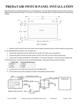
Ground Wire
The BLACK wire connects to the pin next to the light flash jumper
fuse. First strip back a ¾-inch section of the insulation off the
BLACK wire and crimp a ring terminal (not provided) to that wire.
Locate a clean, paint-free metal surface in the drivers kick panel
(do not ground on dash). Using a self-tapping screw, drill the
screw with the ring terminal to the kick panel. Once screwed down,
pull on the wire to ensure a good connection.
Constant Power and Ignition wires
Almost all your power and ignition wires can be found behind the
key cylinder under the lower driver's side dash panel. Using the
appropriate hand tools, remove the lower dash panel taking care
not to break any parts. If the panel does not come off easily, check
for any additional screws you may have missed.
note! More problems are attributed to poor ground
connections than any other cause. Take extra care
to ensure the ground is a clean metal-to-metal
contact and secure.
SELF-TAPPING
BOLT OR SCREW
RING
TERMINAL
GROUND
WIRE
NOTE: REMOVE ANY PAINT
BELOW RING CONNECTOR
DIA-591

13
© 2006 Directed Electronics
Once the lower dash panel has been removed, locate the ignition
harness at the back of the key cylinder. This is usually a group of
heavy gauge wires (approximate 14ga.).
Place the black lead of the LED tester to a clean metal surface in
the kick panel area and secure it. Probe one of the thicker gauge
wires. The ignition wire colors of your specific vehicle can be
obtained at www.autocommand.com.
Testing for Constant Power Wires
W
ARNING! Before making any connection to constant
battery power make sure that the two 30 amp fuses
are removed from the fuse holders on the two pink 12
VOLT wires. Failure to do so may cause fire or short-
ing of sensitive electrical components.

14
© 2006 Directed Electronics
With the key in the off position, test the suspect wire. The
constant power wire will read 12V on the multimeter. Once the
constant power wire has been identified, solder the two heavy
gauge 12 VOLT wires (PINK) from the control module to it and
wrap the connection with electrical tape.
Testing for Ignition Wires
With the multimeter lead still connected in the kick panel, locate
the suspected ignition wire. It will test differently than constant
12 volts. Place the red lead of the multimeter on the suspected
wire. With the key in the off position the multimeter will read 0.
Turn the key to the on position and the multimeter will read 12
volts. Now, watching your multimeter, turn the key to the crank
position. If the 12 volts stays on, then you have found your igni-
tion wire. If the wire tests correctly, solder the BLUE heavy gauge
wire to it and wrap the connection with electrical tape.
If the vehicle requires more than one ignition as per the web site
information, follow the same test procedure and solder the GREEN
heavy gauge wire to it then wrap the connection with electrical
tape. If your vehicle has only one ignition wire, secure the GREEN
wire and dress it out of the way.
note! If the vehicle has more than one constant
power wire, utilize two of them. Connect one of the
heavy gauge PINK wires to one of the constant
power wires and the other heavy gauge PINK wire to
the other constant power wire.

15
© 2006 Directed Electronics
If your vehicle requires more than two ignitions, an additional
relay (not provided) is required. Refer to the diagram below.
87
87A
86
85
30
+12 VDC CONSTANT (FUSED 20A)
GROUND
GREEN (+) OUTPUT
TO 2
nd
IGNITION
TO 2
nd
IGNITION
TO 3
rd
IGNITION
3
rd
IGNITION RELAY
(NOT PROVIDED)
87
87A
86
85
30
+12 VDC CONSTANT (FUSED 20A)
GROUND
TO 2
nd
IGNITION
2
nd
IGNITION RELAY
(NOT PROVIDED)

16
© 2006 Directed Electronics
Accessory and Starter wires
The starter and accessory wires will be located in the same harness
as the ignition and constant power.
To find the accessory wire leave the multimeter’s black lead
connected to ground. Take the red lead and probe the wire
suspected to be the accessory wire. With the key off, your multi-
meter should read 0 volts. Turn the key to the on position the
multimeter should read 12 volts. Now turn the key to the crank
position. If you have the correct accessory wire the multimeter
will read 0 volts while the starter is cranking and 12 volts once
the key returns to the on position. If the wire tests correctly, strip
some insulation off and solder the WHITE heavy gauge wire and
wrap it with electrical tape.
If your vehicle requires more than one accessory then the GREEN
ign2 wire can be programmed to function as an accessory output.

17
© 2006 Directed Electronics
If the GREEN wire is being used for ign2 an additional relay (not
provided) is required for a 2nd accessory. Refer to the diagram
below.
Now that the accessories have been located, find the suspected
starter wire according to the web information. Leave the black
lead of your tester on ground and place the red lead of your multi-
meter on this wire. The multimeter should read 0 volts in all key
positions except the crank position. In the crank position your
multimeter should read 12 volts, and will go to 0 volts when the
starter disengages.
87
87A
86
85
30
+12 VDC CONSTANT (FUSED 20A)
GROUND
TO 2
nd
ACCESSORY
WHITE (+) 30A OUTPUT TO
ACCESSORY CIRCUIT
TO ACCESSORY
2
nd
ACCESSORY RELAY
(NOT PROVIDED)
87
87A
86
85
30
+12 VDC CONSTANT (FUSED 20A)
GROUND
TO ACCESSORY
ACCESSORY RELAY
(NOT PROVIDED)
/