Page is loading ...

3-way globe valve for feedwater heater inlet bypass
Installation and Maintenance Instructions
Emerson reserves the right to change the contents without notice RAIIC-0054-EN-1310
Introduction
This manual provides guidelines to be observed for the following operations:
• storage
• installation into the pipeline
• maintenance
• preservation
The manual is intended for the following personnel/staff:
• plant warehouse staff
• installers
• maintenance engineers
1. Verification upon receipt and storage before installation
When the materials arrive, it is recommended to:
• Check the integrity of the case.
• Open the case and verify that there is no damage due to transportation.
• Do not open the barrier bag (if present).
• Verify that the contents are those stated on the packing list.
• Store the valves (unless damaged) in their original packaging.
Please observe the following:
1. Store the valves in a closed, clean and dry storage room.
2. Do not place packages directly on the ground.
3. Check the packages every two months.
4. Substitute the silica gel every six months. This is not applicable in the case of barrier bag
packages.
2. Handling
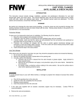
During handling operations, valves must be lifted and handled as indicated in fig. 1 by using lifting
equipment (fasteners, hooks, etc.) that must be sized and selected on the basis of valve weight
(indicated in the drawings).
If there are any eyebolts in the valve body, these can be used to lift the valve.
Do not use any lifting points located on the actuator to lift the valve. These lifting points are to lift
the actuator only.
Lifting and handling must be done only by qualified personnel.
Warning
This symbol means “Warning” and indicates all matters relating to safety. Please read the
warning notices carefully and follow the instructions. These serve to guarantee your safety
and to prevent damage to people and property.
Warning
Do not use any lifting straps that are either damaged or of inadequate/unknown size.
In addition to the instructions in this manual, specific plant safety regulations must always be
followed.
It is recommended that this manual is read carefully and entirely, before starting any
maintenance, in order to optimize intervention timing, and to ensure that suggested spare
parts and gaskets are available in the event of valve assembly.
For installation and maintenance operations no specific equipment or tools are required, other
than those usually available in the plant.
Emerson is always at the Customer’s disposal for any further technical information.
Index
Introduction 1
1. Verification upon receipt
and storage before installation 1
2. Handling 1
3. Installation 2
4. Scheduled maintenance 2
5. Troubleshooting Guide 3
6. Disassembly instructions 4
7. Assembly instructions 4
8. Spare parts list 5
9. Attachments 6
Fig. 1 - Valve lifting and handling
RAIMONDI
www.valves.emerson.com

3-way globe valve for feedwater heater inlet bypass
Installation and Maintenance Instructions
Emerson reserves the right to change the contents without notice page 2
3. Installation
The valves must be installed in horizontal pipes with the stem in vertical position.
The following operations must be performed only immediately before the installation:
1. Remove the protection caps of the end faces.
2. Check the upstream and downstream pipeline sections. Make sure that there are no solid
particles or any other kind of dirt or debris inside. If necessary, clean carefully by using an air
line.
3. Pay attention to the flow direction.
Warning
Before starting the installation of the
valve, please verify that the valve
class is suitable for the required
operating pressure, and the materials of
construction are suitable for the intended
service (type of process fluid).
Warning
Protect eyes with appropriate welding
masks or goggles during all welding
operations.
Warning
Verify that the flow direction of the line corresponds to the flow direction indicated by the
arrow on the valve body.
General notes
• In order to avoid damage during welding and post welding heat treatment, we suggest to
disassemble the internal part following the instructions given in section 6 of this manual.
• In case that one end of the valve is not connected to the line for a period of time longer than
half a day, the open end must be properly closed and sealed in order to prevent entry of dirt or
debris.
• Check that there is sufficient space to easily disassemble the valve.
Verify that the valve is aligned with the pipe. Proceed with welding in accordance with the
procedure indicated by the engineering company that designed the plant.
During site welding of the valve to the pipe, the valve and adjacent piping must be supported so
that the pipeline stresses are not transmitted to the valve body.
Usually, the first weld layer will be made with TIG, while following weld layers will be made with
the
appropriate electrode for the valve body material.
Welding and stress relieving procedures should conform to the applicable code or standard.
4. Scheduled maintenance
4.1 Routine inspection
Normal check
• Verify once a month that there is no leakage from packing or in the body/bonnet area.
a. In case of leakage from the packing, tighten the appropriate gland nuts and bolts according
to the procedures described in the assembly section.
b. In case of leakage from the body/bonnet gasket, tighten the bonnet support bolts as stated in
the re-assembly procedure. Otherwise de-pressurize the line as soon as possible in order to
prevent erosion.
• Verify bearings greasing and stem thread every two or three months, depending on operating
frequency.
• For actuated valves, refer also to the actuator manual in addition to the above.
Preventive
• Verify the tightness of gland bolts every three months.
• Grease the stem and bearings every six months for motorized valves and every eight months for
hand-operated valves.
• Check the travel of the gland follower every twelve months. Install a new packing when the end
of the travel is approaching.
• Disassemble critical and/or actuated valves every four years. Verify the sealing surfaces and lap
them if necessary. Substitute the bonnet gasket and the packing. Grease the stem.
• For the actuator, proceed as indicated in its maintenance manual.
Fig. 2 - Possible installation positions

3-way globe valve for feedwater heater inlet bypass
Installation and Maintenance Instructions
Emerson reserves the right to change the contents without notice page 3
5. Troubleshooting guide
The damages listed here below are the most frequent ones that may occur.
5.1 Leakage from the packing
When there is humidity or droplets near the packing area, the stem or the gland, and these cannot
be corrected by tightening the gland bolts, you may want continuing the work of the line until
the first stop of the plant. In this case, the stem can be set in backseat position, verifying the
following:
• Packing may have hardened. In this case, it must be replaced.
• The gland is at the end of its travel. This means that the packing cannot be compressed.
Packing must be replaced.
• Scratches, scorings or other marks may be found in the stem. It may also have got bound. In
these cases, the stem must be replaced.
• The gland may be jammed on the stem because of a non-uniform tightness of the gland bolts.
Release the gland bolts. Move the gland and set it again; then tighten the bolts progressively.
5.2 Leakage from body/bonnet joint
Leakage under operation from the pressure seal joint requires immediate action, since it may
cause major damage to the valve.
Typical causes for leakage are:
• Previous incorrect reassembly of the valve.
• Re-using pressure seal gasket.
• A defect inside the valve body.
5.4 Jamming of valve along the stroke
If a higher effort is required at some points than in others when operating the valve, proceed as
follows:
• Examine the stem and make sure that there is no picking-up in either the smooth or the
threaded parts.
• Disassemble the valve, as a seizure may be starting to form between body guides and disc.
5.5 Problems relevant to motor operators
For these problems, refer to the actuator instruction manual.
5.3 Leakage between seat and disc
In case of leakage between seat and disc, we recommend to perform closing and opening
operations with a pressure differential. If leakage persists, check that:
• No foreign material is locked between seat and disc, scoring the sealing surfaces.
• No foreign material is deposited between the seats, thus preventing the disc from closing.
• Incomplete previous closing allowed the fluid to impact onto the seal surfaces, eroding these.
• The valve has been used for line flushing, and therefore seats have been damaged by foreign
material.
For all the above cases it is absolutely necessary to disassemble the valve as soon as
possible and proceed with an inspection of the internal parts in order to reduce further
damage.

3-way globe valve for feedwater heater inlet bypass
Installation and Maintenance Instructions
Emerson reserves the right to change the contents without notice page 4
6. Disassembly Instructions
When disassembling valves, follow the instructions reported here below. Before starting any
operation, it is important to:
• identify the problem
• clean the area around the valve that is to be disassembled
• make available a box and/or a pallet for all components
• make available a polyethylene sheet to protect all components and to avoid that any particles
inadvertently enter the body.
1. Fully close the valve.
2. Loosen and remove the nuts (26.1), remove the position indicator.
3. Loosen and remove the nuts (9).
4. Using suitable lifting equipment, lift the handwheel/yoke assembly.
5. Loosen and remove the gland nuts (17), gland flange (16) and gland (15).
6. Remove safety ring (4).
7. Knock down the bonnet (2) with a soft-faced hammer to relieve the load on the segment ring
(5), by pushing them outside through the four radial holes in the body.
8. Reassemble the safety ring and nuts (4).
9. Tighten the nuts (11) of the bonnet bolts (10) evenly, until the bonnet is lifted. Remove the ring
(6) and the pressure seal gasket (7).
10. After the gasket has been removed, proceed by removing the bonnet (2) assembly with stem
(20) and disc(28).
Refer to figs. 3 and 4
7. Assembly Instructions
Before starting assembly it is recommended to verify the following points:
• Remove any dirt or particles with a wire brush or abrasive cloth; remove any oil or grease with a
suitable solvent, to avoid damage cause by foreign particles – in particular on the sealing area.
• Never re-use the old gaskets, even though they seem to be in good condition.
• Verify that there are no scratches on the body sealing area.
1. Place the disc (28) on a clean flat surface, then fit the stem (20) into the disc.
2. Fit the disc nut (30) over the stem (20), screw into the disc (28) and then tighten. Ensure that
the stem is free to move. Then tack weld the disc nut to the disc.
3. Fit the bonnet assembly with stem (20) and disc (28) into body (1).
4. Place a new pressure seal gasket on the bonnet.
5. Assemble the ring (6) and the segment rings (5).
6. Insert the safety ring (4) and tighten the nuts (10) to the torque values stated in table 2.
7. Fit the ground ring (13), a new gland packing (14), gland (15), gland flange (16) and gland nuts
(17), and tighten these evenly. DO NOT over-tighten as this will cause high friction loads on
the stem.
8. Using suitable lifting equipment, carefully lower the handwheel/yoke assembly onto the valve,
taking care not to damage the yoke studs (8). Secure the assembly by cross-tightening the
yoke nuts (9).
10. Fit the position indicator (25)
11. After the valve has been pressurized, verify that the nuts (9) are tightened by following the
tightening torque values indicated in table 1.
Warning
Before starting disassembly it is very
important to verify – for your safety –
that:
• the line is not pressurized
• the line is at room temperature
• the line is drained
• all electrical supplies have been
switched off and disconnected prior to
dismantling the valve.

Emerson reserves the right to change the contents without notice page 5
3-way globe valve for feedwater heater inlet bypass
Installation and Maintenance Instructions
8. Spare parts list
Emerson guarantees the supply of any spare part for a period of at least ten years from the
manufacturing date (month/year) indicated on the tag plate.
The main objective in formulating a service parts inventory policy is the capability to provide
prompt valve service, thus preventing extension of maintenance down time. To accomplish this,
it is necessary to have the proper service parts immediately available for the optimum number of
valves. This can be achieved at a minimum cost by defining the inventory on a frequency of need
basis.
To assist in reaching this objective, the field service and repair organization of Raimondi
recommends following these guidelines in order to establish inventory levels:
1. Identify the total number of valves in service by size, type number, pressure/temperature class,
tag number.
2. Identify the frequency of replacement tendency of specific parts:
Class I Parts most frequently replaced.
Class II Parts less frequently replaced, but critical in the event of an emergency requirement.
Class III Parts seldom replaced
Class IV Hardware (e.g. nuts, bolts, pins, cap components etc.)
Class V Parts practically never requiring replacement
3. “Operational reliability” is defined as a probable percentage (%) of total, uninterrupted
operational time that can be expected by stocking predetermined valve component
classifications. Determine the “operational reliability” which is compatible with a specific
company’s operational objectives and service parts inventory investment policy. Then relate
operational reliability to part classifications, which will satisfy that need.
Guidelines are as follows:
Parts classification Operational Reliability
Class I 70%
Class I and II 85%
Class I, II and III 95%
Class I, II, III and IV 99%
4. Consult recommended spare parts list by valve type to determine quantity of parts valves to be
covered by the inventory plan.
5. Select parts and specify quantities.
Classification of spare parts
Classification Item No. Description
CLASS I 7 Pressure seal
Parts most frequently replaced 14 Gasket
37 O-ring
CLASS II 20 Stem
Parts less frequently replaced but 15 Gland
critical in case of an emergency 28 Disc
30 Disc nut
33 Socket head screw
CLASS III 25 Position indicator
Parts seldom replaced 16 Gland flange
CLASS IV 8 Body/yoke stud
Hardware (e.g. nuts, studs, pins, etc.) 9 Body/yoke nut
10 Body/bonnet stud
11 Body/bonnet stud
18 Gland stud
17 Gland nut
CLASS V Balance
Parts practically never requiring
replacement

32
22
24
21
36
26.1
26
18
17
16
15
14
5
6
7
31
30
28
1.3
35
23
24
20
3
25
19
8
9
11
10
4
13
2
33
37
1
28.1
525 190
400 335
49
325 325
1930
1000325
595
32
22
24
21
36
26.1
26
18
17
16
15
14
5
6
7
31
30
28
1.3
35
23
24
20
3
25
19
8
9
11
10
4
13
2
33
37
1
28.1
525 190
400 335
49
325 325
1930
1000325
595
Emerson reserves the right to change the contents without notice page 6
3-way globe valve for feedwater heater inlet bypass
Installation and Maintenance Instructions
9. Attachments
The reference drawings are those relating to the supply only. The drawings are typical drawings
only and may not represent the valves supplied.
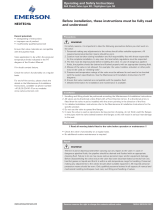
Fig. 3 - 3-way globe valve for preheater inlet
Table 1 - Parts list
Pos. Part name Material Pos. Part name Material Pos. Part name Material
1 Body 15NiCuMoNb5
1.3 Body seat surface A 182 F6A
2 Bonnet A 105
3 Yoke A 105 + St 35
4 Safety ring A 105
5 Segment ring A 105
6 Ring A 105
7 Body/bonnet gasket Pure graphite
8 Body/bonnet bolts A 193 B7
9 Body/bonnet nuts A 194 2H
10 Nuts A 194 2H
11 Bolts A 193 B7
13 Ground ring A 182 F6A
14 Packing Pure graphite
15 Gland A 182 F6A
16 Gland flange A 105
17 Gland nuts A 194 2H
18 Gland bolts A 193 B7
19 Gland gasket Graphite
20 Stem X35CrMo17
21 Yoke nut B 148 Gr. B
22 Bearings C. steel
23 Flange A 105
24 Socket head screw Class 12.9
25 Position indicator A 105
26 Security pin Class 12.9
26.1 Nut Class 65
27 Lubricator C. steel
28 Disc A 105
28.1 Disc surface A 182 F6A
30 Disc nut A 182 F6A
31 Cylinder A 182 F6A
32 O-ring Viton A-75° Sh.A
33 Socket head screw Stainless steel
35 Key AISI 4140
36 Stem key AISI 4140
37 O-ring KAFLON 82B - 82° Sh.A
49 Actuator: AUMA GST 30.1 - 8:1
+ SIPOS 2SA5053 / rpm 112
Inlet
By-pass
Outlet

3-way globe valve for feedwater heater inlet bypass
Installation and Maintenance Instructions
Emerson reserves the right to change the contents without notice page 7
Table 2 - Tightening torque values for bolts/screws
Body/yoke - Bolts/screws: A 193 B7 Bonnet - Bolts/screws: A 193 B7
Ø Bolts/screws Torque values Ø Bolts/screws Torque values
Kgm (Nm) Kgm (Nm)
M12 5 (50) M12 1 (9)
M16 10 (100) M16 2 (18)
M20 17 (170) M20 3 (30)
M22 29 (280) M22 5 (48)
M24 43 (420) M24 7,5 (73)
M30 61 (600) M30 11 (105)
M33 86 (850) M33 15 (150)
M36 112 (1100) M36 21 (205)
Stem Gland bolts: A 193 B7
Diam. M16 M18 M20 M22 M24 M27 M30 M33
25,4 1,90 2,10 2,40 2,60 2,80 3,20 3,60 3,90
31,8 3,00 3,30 3,70 4,00 4,40 5,00 5,60 6,10
34,9 3,30 3,60 4,00 4,40 4,80 5,40 6,00 6,60
44,5 4,90 5,50 6,10 6,60 7,30 8,20 9,10 10,00
50,8 6,60 7,40 8,20 8,80 9,70 11,00 12,20 13,40
57,2 8,60 9,60 10,60 11,40 12,60 14,20 15,80 17,30
63,5 9,40 10,40 11,50 12,50 13,70 15,50 17,30 18,80
69,8 10,10 11,30 12,50 13,50 14,90 16,80 18,70 20,40
76,2 12,70 14,10 15,60 16,80 18,50 21,00 23,30 25,40
82,5 13,90 15,50 17,10 18,50 20,40 23,00 25,60 28,00
95,3 15,30 17,00 18,80 20,30 22,40 25,30 28,10 30,70
Table 3 – Suggested greases
Manufacturers Suggested Greases for bearings
Agip GRMUEP2
API PGX2
BP Grease LTX 2
Esso Beacon 2
Fina Finagrease HP Finagrease EPL2
Mobil Mobilux EP2
Q8 Q8 Rembrandt EP2
Shell Alvania R2 Supergrease A
Texaco Multifak EP2 Grease L2
Total Multis EP2 Multis 2
Viscol Signal Rolsfer 2
Apply Molykote to the stem threads.
All other bolts and nuts are assembled with usual lubricant or Molykote.
• Select the constant in relation to stem diameter and packing bolt size
• In order to obtain the packing bolt torque in Nm multiply the selected constant for pressure in
MPa
Example
Valve under pressure of 24 MPa with steam diameter equal to 44,5 mm and packing bolt size
equal to M16
a. Constant is equal to 4,9
b. Packing bolts torque is equal to
4,9 x 24 = 117,6 Nm
/