Page is loading ...

OWNER’S SERVICE MANUAL
MANUEL D’ATELIER DU
PROPRIETAIRE
FAHRER- UND
WARTUNGSHANDBUCH
MANUALE DI SERVIZIO DEL
PROPRIETARI
O
YZ125
(
D
)
1SR-28199-31
PRINTED IN JAPAN
2012.08—0.8 × 1
!
(E, F, G, H)
PRINTED ON RECYCLED PAPER
2013
YZ125
(
D
)
2013
q Read this manual carefully before operating this vehicle.
q Il convient de lire attentivement ce manuel avant la première utilisation du véhicule.
q
Bitte lesen Sie diese Bedienungsanleitung sorgfältig durch, bevor Sie das Fahrzeug in Betrieb nehmen.
q Leggere attentamente questo manuale prima di utilizzare questo veicolo.
1SR-9-31_cover.indd 1 2012/09/15 15:56:32

Q
Read this manual carefully before operating this vehicle. This manual should stay with this vehicle if it is sold.
Q
Il convient de lire attentivement ce manuel avant la première utilisation du véhicule. Le manuel doit
être remis avec le véhicule en cas de vente de ce dernier.
Q
Bitte lesen Sie diese Bedienungsanleitung sorgfältig durch, bevor Sie das Fahrzeug in Betrieb nehmen.
Diese Bedienungsanleitung muss, wenn das Fahrzeug verkauft wird, beim Fahrzeug verbleiben.
Q
Leggere attentamente questo manuale prima di utilizzare il veicolo. Questo manuale dovrebbe
accompagnare il veicolo se viene venduto.

YZ125(D)YZ125(D)
20132013
1SR-28199-31-E01SR-28199-31-E0
OWNER’S SERVICE MANUALOWNER’S SERVICE MANUAL
Read this manual carefully before operating this vehicle.Read this manual carefully before operating this vehicle.


YZ125 (D)
OWNER'S SERVICE MANUAL
©2012 by Yamaha Motor Co., Ltd.
1st Edition, September 2012
All rights reserved.Any reprinting or
unauthorized use without the written
permission of Yamaha Motor Co., Ltd.
is expressly prohibited.
Printed in Japan

FOREWORD
INTRODUCTION
Congratulations on your purchase of
a Yamaha YZ series. This model is
the culmination of Yamaha's vast ex-
perience in the production of paceset-
ting racing machines. It represents
the highest grade of craftsmanship
and reliability that have made Yama-
ha a leader.
This manual explains operation, in-
spection, basic maintenance and tun-
ing of your machine. If you have any
questions about this manual or your
machine, please contact your Yama-
ha dealer.
Yamaha continually seeks advance-
ments in product design and quality.
Therefore, while this manual contains
the most current product information
available at the time of printing, there
may be minor discrepancies between
your machine and this manual. If you
have any questions concerning this
manual, please consult your Yamaha
dealer.
PLEASE READ THIS MANUAL
CAREFULLY AND COMPLETELY
BEFORE OPERATING THIS MA-
CHINE. DO NOT ATTEMPT TO OP-
ERATE THIS MACHINE UNTIL YOU
HAVE ATTAINED A SATISFACTO-
RY KNOWLEDGE OF ITS CON-
TROLS AND OPERATING
FEATURES AND UNTIL YOU HAVE
BEEN TRAINED IN SAFE AND
PROPER RIDING TECHNIQUES.
REGULAR INSPECTIONS AND
CAREFUL MAINTENANCE,
ALONG WITH GOOD RIDING
SKILLS, WILL ENSURE THAT YOU
SAFETY ENJOY THE CAPABILI-
TIES AND THE RELIABILITY OF
THIS MACHINE.
IMPORTANT MANUAL
INFORMATION
Particularly important information is
distinguished in this manual by the
following notations.
This is the safety alert symbol. It is
used to alert you to potential per-
sonal injury hazards. Obey all safe-
ty messages that follow this
symbol to avoid possible injury or
death.
A WARNING indicates a hazardous
situation which, if not avoided,
could result in death or serious in-
jury.
A NOTICE indicates special pre-
cautions that must be taken to
avoid damage to the vehicle or oth-
er property.
A TIP provides key information to
make procedures easier or clearer.
SAFETY INFORMATION
THIS MACHINE IS DESIGNED
STRICTLY FOR COMPETITION
USE, ONLY ON A CLOSED
COURSE. It is illegal for this machine
to be operated on any public street,
road, or highway. Off-road use on
public lands may also be illegal.
Please check local regulations before
riding.
• THIS MACHINE IS TO BE OPER-
ATED BY AN EXPERIENCED RID-
ER ONLY.
Do not attempt to operate this ma-
chine at maximum power until you
are totally familiar with its character-
istics.
• THIS MACHINE IS DESIGNED TO
BE RIDDEN BY THE OPERATOR
ONLY.
Do not carry passengers on this
machine.
• ALWAYS WEAR PROTECTIVE
APPAREL.
When operating this machine, al-
ways wear an approved helmet with
goggles or a face shield. Also wear
heavy boots, gloves, and protective
clothing. Always wear proper fitting
clothing that will not be caught in
any of the moving parts or controls
of the machine.
• ALWAYS MAINTAIN YOUR MA-
CHINE IN PROPER WORKING
ORDER.
For safety and reliability, the ma-
chine must be properly maintained.
Always perform the pre-operation
checks indicated in this manual.
Correcting a mechanical problem
before you ride may prevent an ac-
cident.
• GASOLINE IS HIGHLY FLAMMA-
BLE.
Always turn off the engine while re-
fueling. Take care to not spill any
gasoline on the engine or exhaust
system. Never refuel in the vicinity
of an open flame, or while smoking.
• GASOLINE CAN CAUSE INJURY.
If you should swallow some gaso-
line, inhale excess gasoline vapors,
or allow any gasoline to get into
your eyes, contact a doctor immedi-
ately. If any gasoline spills onto
your skin or clothing, immediately
wash skin areas with soap and wa-
ter, and change your clothes.
• ONLY OPERATE THE MACHINE
IN AN AREA WITH ADEQUATE
VENTILATION.
Never start the engine or let it run
for any length of time in an enclosed
area. Exhaust fumes are poison-
ous. These fumes contain carbon
monoxide, which by itself is odor-
less and colorless. Carbon monox-
ide is a dangerous gas which can
cause unconsciousness or can be
lethal.
• PARK THE MACHINE CAREFUL-
LY; TURN OFF THE ENGINE.
Always turn off the engine if you are
going to leave the machine. Do not
park the machine on a slope or soft
ground as it may fall over.
• THE ENGINE, EXHAUST PIPE,
MUFFLER, AND OIL TANK WILL
BE VERY HOT AFTER THE EN-
GINE HAS BEEN RUN.
Be careful not to touch them or to
allow any clothing item to contact
them during inspection or repair.
• PROPERLY SECURE THE MA-
CHINE BEFORE TRANSPORTING
IT.
When transporting the machine in
another vehicle, always be sure it is
properly secured and in an upright
position and that the fuel cock is in
the "OFF" position. Otherwise, fuel
may leak out of the carburetor or
fuel tank.

HOW TO USE THIS MANUAL
FINDING THE REQUIRED PAGE
1. This manual consists of seven
chapters; "General Information",
"Specifications", "Regular inspec-
tion and adjustments", "Engine",
"Chassis", "Electrical" and "Tun-
ing"
2. The table of contents is at the be-
ginning of the manual. Look over
the general layout of the book be-
fore finding then required chapter
and item.
Bend the book at its edge, as
shown, to find the required fore
edge symbol mark and go to a
page for required item and de-
scription.
MANUAL FORMAT
All of the procedures in this manual
are organized in a sequential, step-
by-step format. The information has
been complied to provide the me-
chanic with an easy to read, handy
reference that contains comprehen-
sive explanations of all disassembly,
repair, assembly, and inspection op-
erations.
In this revised format, the condition of
a faulty component will precede an
arrow symbol and the course of ac-
tion required will follow the symbol,
e.g.,
• Bearings
Pitting/damage → Replace.

HOW TO READ DESCRIPTIONS
To help identify parts and clarify pro-
cedure steps, there are exploded dia-
grams at the start of each removal
and disassembly section.
1. An easy-to-see exploded diagram
"1" is provided for removal and
disassembly jobs.
2. Numbers "2" are given in the or-
der of the jobs in the exploded di-
agram. A number that is enclosed
by a circle indicates a disassem-
bly step.
3. An explanation of jobs and notes
is presented in an easy-to-read
way by the use of symbol marks
"3". The meanings of the symbol
marks are given on the next page.
4. A job instruction chart "4" accom-
panies the exploded diagram,
providing the order of jobs, names
of parts, notes in jobs, etc.
5. For jobs requiring more informa-
tion, the step-by-step format sup-
plements "5" are given in addition
to the exploded diagram and job
instruction chart.
ILLUSTRATED SYMBOLS (Refer to
the illustration)
Illustrated symbols "1" to "7" are used
to identify the specifications appear-
ing in the text.
1. With engine mounted
2. Filling fluid
3. Lubricant
4. Special tool
5. Tightening
6. Specified value, Service limit
7. Resistance (Ω), Voltage (V),
Electric current (A)
Illustrated symbols "8" to "14" in the
exploded diagrams indicate grade of
lubricant and location of lubrication
point.
8. Apply engine mixing oil
9. Apply transmission oil
10. Apply molybdenum disulfide oil
11. Apply brake fluid
12. Apply lightweight lithium-soap
base grease
13. Apply molybdenum disulfide
grease
14. Apply silicone grease
Illustrated symbols "15" to "16" in the
exploded diagrams indicate where to
apply a locking agent and where to in-
stall new parts.
15. Apply locking agent (LOC-
TITE
®
)
16. Use new one
1
2
3
4
5

TABLE OF CONTENTS
GENERAL INFORMATION
1
SPECIFICATIONS
2
REGULAR INSPECTION AND
ADJUSTMENTS
3
ENGINE
4
CHASSIS
5
ELECTRICAL
6
TUNING
7

CONTENTS
CHAPTER 1
GENERAL
INFORMATION
LOCATION OF IMPORTANT
LABELS............................ 1-1
DESCRIPTION ................. 1-5
CONSUMER
INFORMATION................. 1-6
INCLUDED PARTS .......... 1-6
IMPORTANT
INFORMATION................. 1-6
CHECKING OF
CONNECTION.................. 1-7
SPECIAL TOOLS ............. 1-8
CONTROL
FUNCTIONS ................... 1-11
STARTING AND
BREAK-IN ...................... 1-12
TORQUE-CHECK
POINTS........................... 1-13
CLEANING AND
STORAGE ...................... 1-14
CHAPTER 2
SPECIFICATIONS
GENERAL
SPECIFICATIONS............ 2-1
MAINTENANCE
SPECIFICATIONS............ 2-2
TIGHTENING TORQUES . 2-7
CABLE ROUTING
DIAGRAM....................... 2-13
CHAPTER 3
REGULAR INSPEC-
TION AND AD-
JUSTMENTS
MAINTENANCE
INTERVALS......................3-1
PRE-OPERATION
INSPECTION AND
MAINTENANCE................3-5
ENGINE ............................3-6
CHASSIS ..........................3-9
ELECTRICAL .................3-19
CHAPTER 4
ENGINE
SEAT, FUEL TANK AND
SIDE COVERS.................. 4-1
EXHAUST PIPE AND
SILENCER ........................ 4-3
RADIATOR ....................... 4-5
CARBURETOR AND
REED VALVE ................... 4-7
CYLINDER HEAD, CYLIN-
DER AND PISTON .........4-12
CLUTCH ......................... 4-19
KICK SHAFT AND
SHIFT SHAFT.................4-23
YPVS GOVERNOR......... 4-28
WATER PUMP................4-30
CDI MAGNETO............... 4-33
ENGINE REMOVAL .......4-35
CRANKCASE AND
CRANKSHAFT ............... 4-39
TRANSMISSION, SHIFT
CAM AND SHIFT FORK.4-44
CHAPTER 5
CHASSIS
FRONT WHEEL AND REAR
WHEEL .............................5-1
FRONT BRAKE AND
REAR BRAKE ..................5-6
FRONT FORK.................5-16
HANDLEBAR..................5-24
STEERING ......................5-29
SWINGARM ....................5-33
REAR SHOCK
ABSORBER....................5-38
CHAPTER 6
ELECTRICAL
ELECTRICAL COMPO-
NENTS AND WIRING DIA-
GRAM ...............................6-2
IGNITION SYSTEM...........6-3
CHAPTER 7
TUNING
ENGINE.............................7-1
CHASSIS ..........................7-6

1-1
LOCATION OF IMPORTANT LABELS
GENERAL INFORMATION
LOCATION OF IMPORTANT LABELS
Please read the following important labels carefully before operating this vehicle.
CANADA
1

1-2
LOCATION OF IMPORTANT LABELS

1-3
LOCATION OF IMPORTANT LABELS
EUROPE
AUS, NZ, ZA

1-4
LOCATION OF IMPORTANT LABELS
Familiarize yourself with the following pictograms and read the explanatory text.
Read Owner's service manual.
This unit contains high-pressure nitrogen gas. Mishandling can cause explosion. Do not incinerate,
puncture or open.
Turn off the main switch after riding to avoid draining the battery.
Use unleaded gasoline only.
Measure tire pressure when tires are cold.
Adjust tire pressure.
Improper tire pressure can cause loss of control.
Loss of control can result in severe injury or death.

1-5
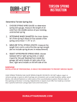
DESCRIPTION
DESCRIPTION
• The machine you have purchased may differ slightly from those shown in the following.
• Designs and specifications are subject to change without notice.
1. Clutch lever
2. Engine stop switch
3. Front brake lever
4. Throttle grip
5. Radiator cap
6. Fuel tank cap
7. Kickstarter crank
8. Fuel tank
9. Radiator
10. Coolant drain bolt
11. Check bolt (Transmission oil level)
12. Rear brake pedal
13. Valve joint
14. Fuel cock
15. Air filter
16. Drive chain
17. Shift pedal
18. Starter knob
19. Front fork

1-6
CONSUMER INFORMATION
CONSUMER INFORMATION
There are two significant reasons for
knowing the serial number of your
machine:
1. When ordering parts, you can
give the number to your Yamaha
dealer for positive identification of
the model you own.
2. If your machine is stolen, the au-
thorities will need the number to
search for and identify your ma-
chine.
VEHICLE IDENTIFICATION
NUMBER
The vehicle identification number "1"
is stamped on the right of the steering
head pipe.
ENGINE SERIAL NUMBER
The engine serial number "1" is
stamped into the elevated part of the
right-side of the engine.
MODEL LABEL
The model label "1" is affixed to the
frame under the rider's seat. This in-
formation will be needed to order
spare parts.
INCLUDED PARTS
DETACHABLE SIDESTAND
This sidestand "1" is used to support
only the machine when standing or
transporting it.
• Never apply additional force to
the sidestand.
• Remove this sidestand before
starting out.
VALVE JOINT
This valve joint "1" prevents fuel from
flowing out and is installed to the fuel
tank breather hose.
In this installation, make sure the
arrow faces the fuel tank and also
downward.
COLLAR (tool for YPVS)
This collar "1" is used to remove and
install the push rod of the engine.
NIPPLE WRENCH
This nipple wrench "1" is used to
tighten the spoke.
IMPORTANT INFORMATION
PREPARATION FOR REMOVAL
AND DISASSEMBLY
1. Remove all dirt, mud, dust, and
foreign material before removal
and disassembly.
• When washing the machine with
high pressured water, cover the
parts follows.
Silencer exhaust port
Side cover air intake port
Crankcase cover hole at the bot-
tom
Water pump housing hole at the
bottom
End of each hose
2. Use proper tools and cleaning
equipment. Refer to "SPECIAL
TOOLS" section.
3. When disassembling the ma-
chine, keep mated parts together.
They include gears, cylinders,
pistons, and other mated parts
that have been "mated" through
normal wear. Mated parts must
be reused as an assembly or re-
placed.

1-7
CHECKING OF CONNECTION
4. During the machine disassembly,
clean all parts and place them in
trays in the order of disassembly.
This will speed up assembly time
and help assure that all parts are
correctly reinstalled.
5. Keep away from fire.
ALL REPLACEMENT PARTS
1. We recommend to use Yamaha
genuine parts for all replace-
ments. Use oil and/or grease rec-
ommended by Yamaha for
assembly and adjustment.
GASKETS, OIL SEALS AND O-
RINGS
1. All gaskets, oil seals, and O-rings
should be replaced when an en-
gine is overhauled. All gasket sur-
faces, oil seal lips, and O-rings
must be cleaned.
2. Properly oil all mating parts and
bearings during reassembly. Ap-
ply grease to the oil seal lips.
LOCK WASHERS/PLATES AND
COTTER PINS
1. All lock washers/plates "1" and
cotter pins must be replaced
when they are removed. Lock
tab(s) should be bent along the
bolt or nut flat(s) after the bolt or
nut has been properly tightened.
BEARINGS AND OIL SEALS
1. Install the bearing(s) "1" and oil
seal(s) "2" with their manufactur-
er's marks or numbers facing out-
ward. (In other words, the
stamped letters must be on the
side exposed to view.) When in-
stalling oil seal(s), apply a light
coating of lightweight lithium base
grease to the seal lip(s). Oil the
bearings liberally when installing.
Do not use compressed air to spin
the bearings dry. This causes dam-
age to the bearing surfaces.
CIRCLIPS
1. All circlips should be inspected
carefully before reassembly. Al-
ways replace piston pin clips after
one use. Replace distorted cir-
clips. When installing a circlip "1",
make sure that the sharp-edged
corner "2" is positioned opposite
to the thrust "3" it receives. See
the sectional view.
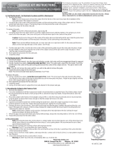
CHECKING OF
CONNECTION
Dealing with stains, rust, moisture,
etc. on the connector.
1. Disconnect:
• Connector
2. Dry each terminal with an air
blower.
3. Connect and disconnect the con-
nector two or three times.
4. Pull the lead to check that it will
not come off.
5. If the terminal comes off, bend up
the pin "1" and reinsert the termi-
nal into the connector.
6. Connect:
• Connector
The two connectors "click" together.
7. Check for continuity with a tester.
• If there in no continuity, clean the
terminals.
• Be sure to perform the steps 1 to 7
listed above when checking the
wire harness.
• For a field remedy, use a contact re-
vitalizer available on the market.
• Use the tester on the connector as
shown.

1-8
SPECIAL TOOLS
SPECIAL TOOLS
The proper special tools are necessary for complete and accurate tune-up and assembly. Using the correct special tool will
help prevent damage caused by the use of improper tools or improvised techniques. The shape and part number used for
the special tool differ by country, so two types are provided. Refer to the list provided to avoid errors when placing an order.
• For U.S.A. and Canada, use part number starting with "YM-", "YU-" or "ACC-".
• For others, use part number starting with "90890-".
Tool name/Part number How to use Illustration
Crankcase separating tool
YU-1135-A, 90890-01135
These tool is used to remove the
crankshaft from either case.
Flywheel puller
YM-1189, 90890-01189
This tool is used to remove the fly-
wheel magneto.
Rotor holding tool
YU-1235, 90890-01235
This tool is used when loosening or
tightening the flywheel magneto se-
curing nut.
Dial gauge and stand
YU-3097, 90890-01252
Stand
YU-1256
These tools are used to check each
part for runout or bent.
Crankshaft installing tool
Crankshaft installing pot
YU-90050, 90890-01274
Crankshaft installing bolt
YU-90050, 90890-01275
Adapter
YU-90063, 90890-01278
Adapter
YU-01499, 90890-01499
These tools are used to install the
crankshaft.
Piston pin puller set
YU-1304, 90890-01304
This tool is used to remove the pis-
ton pin.

1-9
SPECIAL TOOLS
Fuel level gauge "1"
YM-1312-A, 90890-01312
Fuel level gauge adaptor "2"
YM-01470, 90890-01470
This gauge is used to measure the
fuel level in the float chamber.
Radiator cap tester
YU-24460-01, 90890-01325
Radiator cap tester adapter
YU-33984, 90890-01352
These tools are used for checking
the cooling system.
Flywheel puller
YU-33270-B, 90890-01362
These tool is used to split the crank-
case.
Steering nut wrench
YU-33975, 90890-01403
This tool is used when tighten the
steering ring nut to specification.
Cap bolt wrench
YM-01500, 90890-01500
This tool is used to loosen or tighten
the base valve.
Cap bolt ring wrench
YM-01501, 90890-01501
This tool is used to loosen or tighten
the damper assembly.
Tool name/Part number How to use Illustration

1-10
SPECIAL TOOLS
Fork seal driver
YM-A0948, 90890-01502
This tool is used when install the fork
oil seal.
Spoke nipple wrench
YM-01521, 90890-01521
This tool is used to tighten the
spoke.
Pocket tester
YU-3112-C, 90890-03112
Use this tool to inspect the coil resis-
tance, output voltage and amper-
age.
Clutch holding tool
YM-91042, 90890-04086
This tool is used to hold the clutch
when removing or installing the
clutch boss securing nut.
Dynamic spark tester
YM-34487
Ignition checker
90890-06754
This instrument is necessary for
checking the ignition system compo-
nents.
Yamaha Bond No. 1215 (Three-
Bond
®
No. 1215)
90890-85505
This sealant (Bond) is used for
crankcase mating surface, etc.
Tool name/Part number How to use Illustration
/