Bowens ESPRIT DIGITAL 750 Operating Instructions Manual
- Category
- Photo studio flash units
- Type
- Operating Instructions Manual

Esprit Digital 750 (BW-7500 & BW-7505) Instructions BWL-0309/1
BOWENS INTERNATIONAL LIMITED
355 Old Road
Clacton-on-Sea Essex CO15 3RH
Tel: +44(0) 1255 422807
Fax: +44(0) 1255 43634
Esprit
DIGITAL 750
(100V/ 117V/ 230V 50/60Hz)
OPERATING INSTRUCTIONS
Covers Models
BW-7500 BW-7505

Esprit Digital 750 Operating Instructions Esprit Digital 750 Operating Instructions
2 15
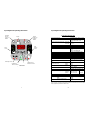
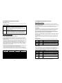
Fig.1 Control Panel
Esprit Digital 750 Specification
Nominal Stored Energy Selectable 750Ws, 500Ws or 250Ws
Supply Voltage AC Auto-ranging 90-130 VAC or 190-
253 VAC with a nominal frequency
of either 50Hz or 60Hz +/-5Hz
Typical Charge Times (Full Power) 230V 50Hz
120V 60Hz
100V 60Hz
<1 sec.
<1.5 secs.
<2.0 secs.
Stabilisation +/- 0.05 f-stop within each range
Modelling Lamp 230V Max 650W
Modelling Lamp 120V Max 300W
Ready Indication Green ‘READY’ light at 100%
charge.
Audible and Modelling light
indication as selected by the user.
Main Fuse (Spare under handle insert) 10A (T)
Modelling Fuse (Spare under handle insert) 4A (F)
Nominal Sync. Voltage 14V
Photocell On/Off
Sounder On/Off
Modelling Power Control Off/Proportional/Independent/100%
IR Remote Control Full control, 12 available channels
(Number depends on transmitter)
Guide Number – Full Power 50° Keylite, 100
ISO
102m, 335ft
Flash Duration t=0.5 250W-s
(Variator set to F10) 500W-s
750W-s
1/3250
1/2240
1/1700
Flash Colour Temperature Approx. 5300K UV coated cover
glass as standard
Flash Variator Power Control 6 f-stops - 5 f-stop range in 1/10
increments, Min (1/32) to Max (1/1)
Recommended Modelling Lamp For 120V 300W 120V CP96
Recommended Modelling Lamp For 230/240V
Preferred
Optional
300W 240V CP97
650W 240V P2/16
BW-2503
Flash Tube Assembly Clear BW-2980
Cover Dome UV Coated BW-2981
Dimensions: Length, dome to handle
Width
Height, excluding bracket
425mm,
150mm,
135mm,
Weight 4.5 Kg, 9lb 14oz
Due to our policy of constant product improvement Bowens International reserve the right to
change equipment specifications without notice.
TEST INT SOUND
AUTO BRACKET
LAMP
POWER
FUNC
250
500
750
PROP
IND
100%
CELL
REMOTE
+B -B
Function
Display
Test Button &
‘READY’ Indicator
IR Remote
Receiver
Control &
Window
Remote
Trigger Cell
Control &
Window
Lamp
Function
Control
Power
Control
Audible & Visual
Indications Controls
Function Display
Controls
Bracketing Controls

Esprit Digital 750 Operating Instructions Esprit Digital 750 Operating Instructions
14 3
WARNINGS & FAULT FINDING
If the unit appears to have developed a fault, first establish that it is a genuine internal fault
and not a case of normal operation such as overheat. Carry out the following checks to
eliminate any external causes. If no obvious problem can be found and replacement of the
modelling lamp, flash tube or fuses do not effect a cure then it is likely that an internal fault
has developed. Always return the unit to an authorised service centre if a fault is suspected
after these checks. UNDER NO CIRCUMSTANCES SHOULD YOU ATTEMPT ANY
REPAIR yourself.
MIS-FIRE Warning
If the unit receives a trigger signal from any of the valid sources (TEST, IR REMOTE, IR
TRIGGER, SYNC) but fails to flash for any reason then the display will flash continuously
and the sounder will beep (if on). Press any button, apart from TEST, to stop this alarm.
Increase the power setting to maximum and use the TEST button to try and flash again. If
the problem continues to happen on more than the odd occasion, particularly at lower power
settings, then it is likely that the tube is wearing out. Before replacing the tube, check that
the trigger wire is correctly connected and is not shorted to or in close proximity to the metal
reflector. If the unit fails to flash at all then check the flash tube for signs of damage or
overheating.
If the unit fails to flash and the display warning is not given then the Sync. lead and/or
camera should be suspected. If possible check these with another flash system. Check the
polarity of the Sync. from the camera and use an adapter to reverse it if necessary. The
DIGITAL 750 supplies a positive SYNC. voltage of 14V with respect to the chassis Ground.
OVERHEAT Warning
The unit is fitted with overheat detectors that turn the modelling lamp off and inhibit charging
until the unit has cooled sufficiently. The display flashes ‘OH’ and the fan continues to cool
the unit while the overheat condition exists. An audible warning is not given since this may
last for some time. Overheat will normally only occur if the unit is flashed repeatedly at a fast
repetition rate or if the cooling fan has failed. Listen for the fan running. Slowing down the
repetition rate will normally help keep the unit out of overheat. Dimming the modelling lamp
or turning it off may also help.
NOTE: The controls are inhibited during overheat to prevent inadvertent changes being
made. If the lamp was on before the OH condition existed then the lamp display will show it
as being temporarily switched off.
The Unit Display Panel Does Not Light
If the display panel does not light when the unit is switched on then first check that the AC
power supply to the unit is OK. Under exceptional conditions of use the main fuse may blow.
This is normal and is designed to protect the unit. Confirm that the main fuse is intact and if
in doubt try a spare. Spare fuses can be found under the rubber covers in the handle. If the
unit immediately blows the main fuse then there is an internal fault.
The Unit Display Panel Lights But Does Not Come To ‘READY’
If this happens then first confirm that the AC power supply is adequate and within the
prescribed limits. Try switching the unit off, wait a minute, then switch on again.
The Modelling Lamp Does Not Light.
Check the modelling fuse and the modelling lamp itself. Replace as required.
GENERAL
Welcome to the world-wide family of Bowens flash equipment users, and congratulations on
selecting the Esprit Digital 750. This has been designed using the latest technology to
produce a unit that is simple to operate, yet has a powerful, highly controllable and accurate
output. Please familiarise yourself with these instructions before operating the unit.
SAFETY NOTES
• The Esprit Digital 750 must not be used in an environment where moisture or flammable
vapour is likely to come in contact with the unit.
• When moving the unit from extremes of temperature and humidity, allow at least one
hour for the unit to stabilise at room temperature before connecting it to the supply.
• A fire hazard exists if flammable materials are placed in close proximity to either the
flashtube or modelling bulb when the unit is in use.
• Do not restrict the slots in the case when in use.
• Care must be exercised when handling equipment that has been in use. The reflector
and front end of the unit can become Very Hot.
• Switch off and disconnect supply before changing fuse(s), modelling bulb or flashtube.
• Only fit a modelling lamp of the correct wattage & rated for the local AC Line voltage.
• The Esprit Digital 750 is protected by a 10A (T) 20mm fuse and a separate 4A (F) 20mm
fuse for the modelling. These are mounted underneath the unit adjacent to the mains
inlet. Never replace either fuse with one of a different rating or type.
• Only connect the unit to a 3-wire, earthed (grounded), supply with an AC Line voltage
within the ranges 90V to 130V or 190V to 253V with a nominal frequency of either 50Hz
or 60Hz. Unregulated or poorly regulated generators should not be used.
• Avoid trailing supply cords and sync leads where they can be tripped over.
• Never use a unit with damaged covers, mouldings, glass dome, flash tube or modelling
bulb. If the unit is dropped or damaged in any way always have it checked out before
using.
• Due to the high voltage / high energy used in the Esprit Digital 750, all servicing should
only be carried out by an authorised Service Centre.
CONTENTS OF CARTON
• Esprit Digital 750 with flashtube
• Sync. cord
• Instructions
• Safety Leaflet
Additional items may be supplied for use in specific countries.

Esprit Digital 750 Operating Instructions Esprit Digital 750 Operating Instructions
4 13
QUICK START GUIDE
The Esprit Digital 750 is very simple to operate once the user has become familiar with the
controls. Detailed operating instructions are given after this Quick Start Guide.
Mounting
Mount the unit on a stand or support system of suitable weight and dimensions to ensure
stable operation of the unit. Ensure that the clamp knob is fully tightened.
Protective Cap
Slide the latch knob back towards the rear of the unit, rotate and remove the plastic
protective cap over the glass cover dome. Always refit the cap when transporting the unit to
avoid damaging the cover dome, flash tube or modelling lamp. NEVER operate the unit with
the cap still in place.
Modelling Lamp
First ensure that the unit is switched off and disconnected from the supply. Confirm that the
lamp and flash tube are securely fitted, particularly before first use or after transporting the
unit. IMPORTANT - Ensure that a modelling lamp rated for the local AC Line voltage is
fitted. Refer to the section on fitting/changing the lamp if required.
Reflector/Accessory System
Fit the desired reflector or accessories and ensure that the latch knob is in the closed
position.
An umbrella mount is available on the mounting bracket. Insert the umbrella shaft, adjust for
distance and secure by tightening the thumb wheel onto the shaft.
AC Supply
Ensure that the AC ON/OFF switch on the unit is set to OFF. Fit the line cord into the AC
inlet socket under the unit and then plug the cord into a suitable AC supply. A 3-wire,
earthed (grounded), supply system must be used to ensure safe and reliable operation of the
unit. The unit will automatically adjust for any AC Line voltage within the ranges 90V to 130V
and 190V to 253V with a nominal frequency of either 50Hz or 60Hz.
Triggering System
Fit the desired trigger source to the SYNC jack socket underneath the unit or use the built-in
Photocell.
Operation
Set the AC ON/OFF switch under the unit to ON. The control panel display at the rear of the
unit will light and, after a short time, the green ‘READY’ indicator should light. If this does not
happen then switch the unit off and refer to the fault finding section.
Adjust the POWER, FLASH & MODELLING controls to provide the desired settings and
select any options required. Refer to the section on operation of the controls if required.
Test flash the unit by pressing the TEST button.
Refer to page 12 if you intend to make continuous use of the fast recycling feature of the unit.
NOTE: If the unit is left unused for 6 months or predominantly used at low power settings it
is recommended that the power be increased to maximum and the unit left switched on
occasionally for at least 30 minutes to help preserve the life of the capacitors.
You are now ready to use the system.
MODELLING LAMP REPLACEMENT
Before attempting to replace the modelling lamp always switch the unit off and unplug it from
the supply. This is particularly important if the lamp glass is broken. Wait a few minutes for
the lamp and tube to cool and for the unit to self-discharge. The unit has a flash off and
auto-dump feature that operates whenever the unit is switched off. This is designed to
quickly reduce the capacitor voltage to a ‘safe’ value but it is still advisable to leave the unit
for as long as possible before changing either the lamp or flash tube.
Remove the glass dome by depressing both buttons and carefully lifting it off. Remove the
lamp by gently pulling it from its socket. Take extra care if the lamp envelope is broken – use
a cloth or gloves.
Natural grease and oils from the hands can dramatically shorten the working life of a lamp so
avoid directly touching the glass envelope of the new lamp. Use the original packing or a
clean cloth to grip the envelope. Accidental contamination may be removed with a clean
cloth and a small quantity of methylated spirits.
Replacement is the reverse of removal but ensure that the lamp is fully inserted into its
socket. If the new lamp fails to light then check the lamp fuse, as this will often rupture when
a lamp fails. Replace a blown fuse with one of the correct type and rating. Always ensure
that any spare fuses are replaced to avoid being without a replacement. For your
convenience these are stored under the rubber covers either side of the handle.
N.B. For maximum safety and lamp life always use the recommended lamp type.
The unit has a built-in ‘soft start’ feature to enhance lamp life but this can be improved further
by dimming or turning the lamp OFF whenever possible. This will also reduce the heat
dissipated by the unit. Avoid moving or knocking the unit when the lamp is switched on or
when it has just been turned off since lamp filaments can be damaged when hot.
FLASH TUBE REPLACEMENT
Before attempting to replace the flash tube always switch the unit off and unplug it from the
supply. Follow the instructions above for removing the cover dome. Avoid directly touching
the glass envelope of the new tube by using the original packing or a clean cloth to grip the
envelope. Remove the trigger wire first and then gently pull the tube from its sockets.
Replacement is the reverse of removal but ensure that the tube is fully inserted into its
socket. Carefully pass the trigger wire through the hole in the trigger tag and tightly wrap the
excess around the tag and back up the wire ensuring that it is kept well away from the metal
base. The wire may be trimmed back if there is too much excess.

Esprit Digital 750 Operating Instructions Esprit Digital 750 Operating Instructions
12 5
INTERMITTENT Option
The preferred mode for the ‘INTERMITTENT’ function can be selected from the ‘OPTIONS’
sub-menu as follows:
Option Description
In.0
Intermittent off. Only available when the LAMP is switched ON (PROP,
IND or 100%). The Modelling Lamp will extinguish while the unit
recharges and light again when the unit reaches ‘READY’. If the unit fails
to flash for any reason then the LAMP will not be extinguished. This is the
default factory setting.
In.1
Intermittent on. Available with the LAMP either ON or OFF. When the unit
reaches ‘READY’, after being flashed, the Modelling Lamp will intensify to
full brightness and then dim before returning to the previous setting (or to
OFF). The exact effect will depend on the current lamp setting. If the unit
fails to flash for any reason then the LAMP will not follow this sequence.
FAST RECYCLING OPERATION
As with any flash unit the useful life of the tube and the unit as a whole depends on the way it
is used. Avoiding excessive HEAT is the key to long life.
The fast recycling feature of the Esprit Digital 750 allows a rapid sequence of high power
flashes to be obtained. However, this feature should be used sparingly since continuous
rapid flashing can cause overheating and subsequent damage to the flash tube and possibly
the internal electronics.
Rapid sequences of flashes are perfectly acceptable but they should always be followed by a
reasonable cooling period, either without flashing or at a substantially reduced rate.
After continuous rapid flashing a cooling period of at least 5 or 10 minutes should be allowed
with the unit left switched on since it will cool much faster than if switched off. Switching a
hot unit off may also cause the OVERHEAT protection to operate. Dimming or turning the
modelling lamp off will also aid cooling.
Whenever possible, avoid rapid high power flashing when using restrictive reflectors such as
a snoot or grid reflector, particularly if the unit is pointing downwards.
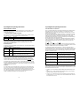
The table below shows the maximum number of flashes permissible at various flash rates
and flash settings before allowing the unit to cool. This cannot cover all combinations but
should be used as a guide to determine the maximum flash rate to meet your requirements.
FLASH SETTING
(ANY POWER)
INTERVAL BETWEEN
FLASHES
MAX NUMBER OF
FLASHES
APPROXIMATE
OPERATING TIME
F10 (FULL) 10 seconds or more Unlimited Continuous
F10 (FULL) 5 seconds 300 30 minutes
F10 (FULL) Less than 1.5 seconds 50 2 minutes
F8.0 (1/4) 5 seconds or more Unlimited Continuous
F8.0 (1/4) 2.5 seconds 900 50 minutes
F8.0 (1/4) Less than 1.5 seconds 150 6 minutes
F5.0 (1/32) 1.5 seconds or more Unlimited Continuous
F5.0 (1/32) Less than 1.5 seconds 1500 60 minutes
MAIN CONTROLS & DISPLAY
Refer to Fig.1. The ‘FUNC’ button, the ‘UP’/’DOWN’ buttons and the three-digit display
provide a simple means of setting and displaying the main functions. Other buttons are used
to access individual functions.
Apart from Bracketing, the unit is designed to retain all settings indefinitely. If for any reason
the memorised settings become corrupted then default settings will be used instead.
‘FUNC’ Button
The ‘FUNC’ button is the main display control and selects the required function for display or
adjustment. Each press of the button selects the next available function as shown by the
leftmost digit or digits. The remaining digit or digits show the value of the function.
NOTE: Certain functions such as the IR Remote and Modelling have to be switched on
before the ‘FUNC’ button can access them. When these are first selected the appropriate
display will be automatically selected for checking or adjustment.
If the ‘FUNC’ or ‘UP’/’DOWN’ buttons are not pressed within 4 seconds then the controls and
display will automatically return to the default ‘FLASH’ function. Use the ‘FUNC’ button to
reselect if required.
Functions likely to require less frequent adjustment are accessible via an ‘OPTIONS’ sub-
menu. This allows the user to customise certain functions without complicating the main
controls.
Function Selection
Momentarily press the ‘FUNC’ button to scroll through the available functions as follows:
Display Range X.X Description
FX.X
5.0 to 10 Display Flash power value. Use ‘UP’ or ’DOWN’ to adjust.
LX.X
5.0 to 10 Display Lamp power value. Use ‘UP’ or ’DOWN’ to adjust.
CXX
0 to 12 Display IR Remote Channel. Use ‘UP’ or ’DOWN’ to
select.
Option Selection
Press and hold down the ‘FUNC’ button for approximately one second until the display
changes to show one of the values below. Release the button. If the SOUNDER is on it will
sound continuously while the ‘FUNC’ button is held down. Now momentarily press the
‘FUNC’ button to scroll through the options until the desired one is reached as follows:
Display Range X.X Description
X.X.X
0.0.0 to 9.9.9 Firmware version.
Br.X
1 to 9 Bracketing value in tenths. Use ‘UP’ or ‘DOWN’ to adjust.
di.X
1 to 9 Display brightness value. Use ‘UP’ or ’DOWN’ to adjust.
Fd.X
0 or 1 Flash dump ON = 1, OFF = 0. Use ‘UP’ or ’DOWN’ to
select.
In.X
0 or 1 Intermittent Lamp ON = 1, OFF = 0. Use ‘UP’ or ’DOWN’
to select.
A more detailed explanation of these options is given in the OPTIONS section.

Esprit Digital 750 Operating Instructions Esprit Digital 750 Operating Instructions
6 11
UP & DOWN Buttons
Select the required ‘FUNC’ as detailed above.
Single presses of the ‘UP’ or ‘DOWN’ buttons will increment or decrement the value by one.
Hold the appropriate button down to automatically increment or decrement the value.
Release the button when the required value is reached and then use momentary presses to
adjust if necessary.
NOTE: Attempting to exceed either the minimum or maximum values for any function will
cause the display to flash. If the sounder is turned on then this will beep to indicate an over
range condition.
FLASH CONTROLS & OPERATION
POWER Button
The maximum available output power of the unit can be selected by pressing the ‘POWER’
button. Each press will select the next setting as indicated by the appropriate LED. This is
equivalent to having three units in one with three maximum values available: 250W-s, 500W-
s & 750W-s. This allows the user a certain amount of control over the flash duration. If a
short flash duration is important then always select the lowest ‘POWER’ setting and the
highest ‘FLASH’ setting possible for the required output.
For each ‘POWER’ setting the displayed ‘FLASH’ power is adjustable over a 5 f-stop range
(6 f-stop points). This provides an overall control range of 6 +7/10 f-stops in 1/10 f-stop
increments.
‘F’ - FLASH Display Mode
The FLASH mode is displayed by default and is indicated by an ‘F’ before the flash value as
follows:
Display Range X.X Description
FX.X 5.0 to 10
Display Flash power value. Use ‘UP’ or ‘DOWN’ to adjust.
The FLASH power is adjustable over a 5 f-stop range (6 f-stops) in 1/10 f-stop increments
using the UP and DOWN push buttons. The power is displayed in an easy to use decimal
form where each whole number represents 1 f-stop. The control has a minimum setting of
5.0 and a maximum setting of 10. A single press of either the UP or DOWN button changes
the value by 0.1 f-stop (1/10) to give a total of 51 values. E.g. If the current value shown is
9.4 then to reduce the power by 1 f-stop just reduce it to 8.4. The following table shows the
whole decimal numbers and equivalent fractional power ratio:
Displayed Power Fractional Equivalent
F10
1 (FULL)
F9.0
1/2
F8.0
1/4
F7.0
1/8
F6.0
1/16
F5.0
1/32 (MIN)
OPTIONS
Firmware Version
The firmware version number can be temporarily displayed from the ‘OPTIONS’ sub-menu
as follows:
Display Range X.X Description
X.X.X 0.0.0 to 9.9.9
Firmware Version Number
It is recommended that this number, together with the Unit Code and Serial Number be noted
at the earliest opportunity in the space provided here:
Unit Code e.g. BW-2950 ____________
Serial Number e.g. PW1234 ____________
Displayed Firmware Version e.g. 1.2.4 ____________
This information can assist us in helping you if problems are ever experienced or if servicing
or repairs are required.
AUTO BRACKETING Option
The preferred value used for the ‘AUTO BRACKETING’ function can be selected from the
‘OPTIONS’ sub-menu as follows:
Display Range Description
br.X 1 to 9
Bracketing value in tenths. Use ‘UP’ or ‘DOWN’ to adjust.
The default factory setting for this is br.3. This is equivalent
to 3/10 or 1/3 f-stop.
DISPLAY BRIGHTNESS Option
The preferred brightness of the display and LED’s can be selected from the ‘OPTIONS’ sub-
menu as follows:
Display Range X.X Description
di.X 1 to 9
Display brightness value where 1 is minimum and 9 is the
maximum. Use ‘UP’ or ‘DOWN’ to adjust. Default factory
setting is di.7.
FLASH DUMP Option
The preferred mode for the ‘AUTO-DUMP’ function can be selected from the ‘OPTIONS’ sub-
menu as follows:
Option Description
Fd.0
Flash dump off. Always resistively dumps excess energy whenever the
FLASH setting is reduced. This is the default factory setting.
Fd.1
Flash dump on. This method attempts to reduce the power in the shortest
possible time whenever the FLASH setting is reduced. The unit
determines whether to resistively dump the excess stored energy or to
dump it quickly by automatically flashing the unit.

Esprit Digital 750 Operating Instructions Esprit Digital 750 Operating Instructions
10 7
INFRA-RED REMOTE CONTROL
The unit has a built in receiver for the optional Infrared Remote Control Transmitter. Switch
the Infrared Remote Receiver on or off using the ‘REMOTE’ button. The IR Remote is on
when the associated LED is lit.
‘C’ - REMOTE CONTROL CHANNEL Display Mode
When the IR Remote is switched on the unit will automatically enter the ‘C’ display mode to
allow adjustment. The ‘C’ before the displayed value indicates this mode:
Display Range X Description
CXX 0 - 12
Display IR Channel number. Use ‘UP’ or ‘DOWN’ to select.
If no adjustment is attempted within 4 seconds then the display will revert to the default
‘FLASH’ mode. If the value needs to be reviewed or adjusted later then use the ‘FUNC’
button to select the ‘CHANNEL’ mode.
IR REMOTE Operation
The following assumes that ‘REMOTE’ has been switched on. The selected channel number
has the following significance:
Location Setting Operation Description
Local Unit
0
Responds to a transmitter set to ANY channel number, 1 to
12 or ALL.
Local Unit
1-12
Responds to a transmitter set to the SAME channel number
or ALL.
Remote
Control
ALL
Causes ALL units, within range, to respond to the Transmitter
regardless of the individual unit channel number.
All functions except ‘REMOTE’ can be controlled remotely, including the local channel
number. This allows the channel number to be changed using the current channel. The new
channel number is only activated after the displayed ‘C’ function times out. This feature
should be used with care particularly when used with several units since individual remote
control of a unit could be lost. This would require the Channel number to be manually reset.
If a transmitter set to a different channel number is activated within range of the unit with the
IR Remote enabled then the channel number of that unit will be briefly displayed. This allows
a quick channel check to made whenever a channel number is unknown. The remote control
can then be switched to that channel.
Restrictions
The actual number of channels available depends on the Remote Control transmitter being
used. Any IR system tends to be directional and although the IR signal can be ‘bounced’ off
objects or walls it may not always work reliably with a number of units that are spaced far
apart. Whenever possible always point the remote control directly towards the sensor on the
unit or units requiring adjustment. The Photocell is very sensitive and the IR Remote is
capable of activating it if used within a range of approximately 1.0m.
AUTO BRACKETING (+B & -B) Buttons
The B+ or B- buttons enable the user to automatically bracket exposures without having to
adjust either the camera or the flash power settings. Once set the DIGITAL 750 will
automatically increase or decrease the FLASH setting by an identical fraction of an f-stop
between three successive shots.
The choice of button determines the setting for the first shot. B- starts the flash sequence
from the lower FLASH setting and B+ starts it from the higher FLASH setting. The FLASH
setting may also be changed once Bracketing has been selected. Once selected the
appropriate Bracketing LED will light. Press the same button again to cancel Bracketing or
press the other button to select the opposite setting.
The new temporary flash value will be shown on the display together with an appropriate
symbol as shown below. The unit will automatically charge or dump to this new value. As
soon as the unit is flashed the display will show the next flash value and symbol in the
chosen sequence:
B+ = Mean = B- =
When the Mean value is automatically selected the two Bracketing LED’s flash alternately.
Either button may be pressed to cancel Bracketing. The unit automatically returns to normal
working on completion of the sequence or if Bracketing is cancelled.
The default factory setting for the bracket value is +/- 3/10 (1/3) f-stop but this may be
changed and memorised to any value between 1/10 and 9/10 by using the OPTIONS menu.
The Bracketing function can be used in a number of ways. The following examples assume
that 3 successive shots will be taken each time, although the sequence may be controlled
manually or cancelled at any time:
Shot Order Required Action
One above, the reference and
then one below.
Set the required reference value first and press B+.
Take shot 1. Take shot 2. Take shot 3
One below, the reference and
then one above.
Set the required reference value first and press B-.
Take shot 1. Take shot 2. Take shot 3
Reference and then two above Select –B first, set the required reference value.
Take shot 1. Take shot 2. Take shot 3
Reference and then two below Select +B first, set the required reference value.
Take shot 1. Take shot 2. Take shot 3
NOTE: The unit has to allow for the flash power to be adjusted by at least the Bracket value
either side of the reference. Because of this the unit will not allow either the FLASH or the
Bracket settings (using the OPTION menu) to be changed to an impossible value. E.g. If the
bracket value has been set to 5/10 then:
1. to allow B+ or B- to be selected, the displayed setting must be within the range F5.5 to
F9.5.
2. if either B+ or B- is currently selected then the displayed setting can only be adjusted
between F6.0 and F10 for B+ or F9.0 and F5.0 for B-.
3. if either B+ or B- is selected and the Bracket value is changed then the limits are determined by
the displayed setting. E.g. if B+ is currently set to F6.2 then the maximum Bracket value will be
6/10 (sequence of F6.2, F5.6, F5.0).

Esprit Digital 750 Operating Instructions Esprit Digital 750 Operating Instructions
8 9
MODELLING LAMP CONTROLS & OPERATION
Four modelling lamp modes are available. Each press of the LAMP FUNCTION button
selects the next mode in sequence. The associated LED shows the mode selected as
follows:
Mode Description
OFF
Lamp switched off, no LED’s lit.
PROP
Proportional - Lamp brightness linked directly to the current flash power
setting.
IND
Independent - Lamp brightness adjustable independently from the flash
setting.
100%
Lamp at full brightness.
‘L’ - LAMP Display Mode
When the ‘LAMP FUNCTION’ is switched to ‘INDEPENDENT’ mode the display and controls
are automatically set to the ‘LAMP’ mode to allow adjustment. An ‘L’ before the displayed
value indicates this mode:
Display Range X.X Description
LX.X 5.0 to 10
Display Lamp power value. Use ‘UP’ or ‘DOWN’ to adjust
If no adjustment is attempted within 4 seconds then the display will revert to the default
‘FLASH’ mode. If the value needs to be reviewed or adjusted later then use the ‘FUNC’
button to select the ‘LAMP’ mode.
The LAMP power is adjustable over a 5 f-stop range (6 f-stops) in 1/10 f-stop increments
using the ‘UP’ and ‘DOWN’ push buttons. Adjustment and display of the ‘LAMP’ power in
‘IND’ mode is identical to that of the ‘FLASH’ power.
TRIGGER SOURCES
TEST/OPEN FLASH RELEASE Button
Press the TEST button to trigger the flash. The unit will only flash if the unit is charged and
the ‘READY’ light is either lit or flashing.
EXTERNAL SYNCHRONISATION Socket
Use the SYNC. jack socket and SYNC. Cord to connect the unit to a camera or other trigger
source. Remote triggering devices such as an Omni-cell may be plugged directly into the
SYNC. jack socket or via an extension lead. The unit will only trigger via the SYNC. Socket if
fully charged and the ‘READY’ LED is lit.
REMOTE PHOTO-CELL Button
Switch the built-in photocell on or off using the ‘CELL’ button. The photocell is on when the
associated LED is lit. The unit will flash when a flash is sensed from another unit or IR
Remote Trigger.
NOTE: The photocell is extremely sensitive but some experimentation with positioning may
be necessary to ensure a reliable trigger, particularly if the cell is hidden from the source.
Avoid directly illuminating the photocell from a continuous light source since this can prevent
correct operation or in some circumstances result in spurious triggering.
AUXILIARY FUNCTIONS
SOUNDER Button
Switch the sounder on or off using the ‘’SOUND’ button. The sounder is on when the
associated LED is lit. The sounder will give a short beep whenever active keys are pressed.
Longer beeps or repetitive beeps provide warnings, the meaning of which is given in the
appropriate section.
INTERMITTENT Button
This feature uses the Modelling Lamp to indicate that the unit has flashed correctly and that it
has recharged to ‘READY’ and is in addition to the normal indication. Press the ‘INT’ button
to switch this function on or off. The associated LED is lit when ‘INT’ is on. Depending on
the ‘OPTION’ setting this mode may be unavailable when the Lamp is ‘OFF’. When this is
the case, and the sounder is on, a long warning beep will be given when the button is
pressed to indicate that it cannot be selected.
The user may select one of two indicating modes for this function by means of the
‘OPTIONS’ sub-menu. See ‘OPTIONS’ for a description of how to access this mode.
The default setting is ‘In.0’. The ‘INTERMITTENT’ function in this mode is only available
when the lamp is switched ON (PROP, IND or 100%). When the unit is flashed the
Modelling Lamp will extinguish while the unit recharges and will light again when the unit
reaches ‘READY’.
The optional mode is ‘In.1’. The ‘INTERMITTENT’ function in this mode is available whether
the lamp is on or off. After the unit is flashed and the unit recharges to ‘READY’ the
Modelling Lamp will intensify to full brightness and then dim before returning to the previous
setting (or to OFF). The exact effect will depend on the actual lamp setting
If the unit fails to flash for any reason then the chosen sequence will not be followed. Note
that the Modelling Lamp indication is relative slow compared to the normal LED and Sounder
indication which means that the unit will actually be ‘READY’ and may, if required, be flashed
before the sequence is complete.
AUTO-DUMP Operation
‘AUTO-DUMP’ automatically discharges the capacitors when the power is reduced. The
‘READY’ indicator flashes while the unit is dumping. The user may select one of two DUMP
methods by means of the ‘OPTIONS’ sub-menu. See ‘OPTIONS’ for a description of how to
access this mode.
The default factory setting is ‘Fd.0’. In this mode the unit resistively dumps excess energy
whenever the flash setting is reduced. This is a relatively slow method and can take several
seconds to reach the required value if the change is large. Use the ‘TEST’ button to
manually flash dump the excess energy quickly if required.
The optional mode is ‘Fd.1’. The unit attempts to automatically reduce the power to the
desired setting in the shortest possible time. It does this by determining how long it would
take to simply resistively dump the excess stored energy compared with flash dumping and
then having to re-charge to the new setting.
To prevent multiple flashes occurring while the setting is being changed the unit waits until
the ‘DOWN’ button is released before deciding whether to flash or not. The result is that
small or slow decreases in the flash setting are unlikely to cause the unit to flash.
The unit is designed to automatically flash, if possible, when turned off. The resistive dump
will continue to reduce any remaining energy while the unit is off. This safety feature cannot
be disabled.
NOTE: The unit may decide to flash if +B is canceled when both the overall Flash power and
Bracket itself are set to high values.
-
 1
1
-
 2
2
-
 3
3
-
 4
4
-
 5
5
-
 6
6
-
 7
7
-
 8
8


Bowens ESPRIT DIGITAL 750 Operating Instructions Manual
- Category
- Photo studio flash units
- Type
- Operating Instructions Manual
Ask a question and I''ll find the answer in the document
Finding information in a document is now easier with AI
Related papers
-
Bowens ESPRIT digital DX1000 Operating Instrctions
-
-
-
-
-
-
-
-
-
Other documents
-
 Hampton Bay DIY-900PS Installation guide
-
 Cononmark i6TEX Operating instructions
-
Broncolor Impact 21 / 41 Owner's manual
-
Elinchrom 300RX User manual
-
-
-
-
 Elinca E26178 Datasheet
-
-
 Fotoquantum FQM 250 User manual


