Page is loading ...

Fluidcontrol
Installation and Operation Instructions
Original instructions
Oil/air cooler
BLK
BE350025
03/2019
Bühler Technologies GmbH, Harkortstr. 29, D-40880 Ratingen
Tel. +49 (0) 21 02 / 49 89-0, Fax: +49 (0) 21 02 / 49 89-20
E-Mail: [email protected]
Internet: www.buehler-technologies.com

Bühler Technologies GmbH, Harkortstr. 29, D-40880 Ratingen
Tel. +49 (0) 21 02 / 49 89-0, Fax: +49 (0) 21 02 / 49 89-20
Internet: www.buehler-technologies.com
E-Mail: [email protected]
Read this instruction carefully prior to installation and/or use. Pay at-
tention particularly to all advises and safety instructions to prevent in-
juries. Bühler Technologies can not be held responsible for misusing
the product or unreliable function due to unauthorised modifications.
All rights reserved. Bühler Technologies GmbH 2019
Document information
Document No.......................................................... BE350025
Version......................................................................... 03/2019

BLK
Contents
1 Introduction..................................................................................................................................................................................................................... 2
1.1 Intended use .........................................................................................................................................................................................................2
1.2 Model key............................................................................................................................................................................................................... 2
1.3 Scope of delivery.................................................................................................................................................................................................. 2
2 Safety instructions......................................................................................................................................................................................................... 3
2.1 Important advice................................................................................................................................................................................................. 3
2.2 General hazard warnings ................................................................................................................................................................................. 3
3 Transport and storage .................................................................................................................................................................................................. 5
4 Installation and connection ........................................................................................................................................................................................6
4.1 Requirements to the installation site............................................................................................................................................................6
4.2 Installing the unit................................................................................................................................................................................................6
4.2.1 Installing swivel nuts in the fitting body ..................................................................................................................................... 6
4.3 Hydraulic connection ......................................................................................................................................................................................... 7
4.4 Electrical connections ........................................................................................................................................................................................ 7
4.4.1 Electrical connections BLK 1-phase ................................................................................................................................................. 8
4.4.2 Electrical connection temperature switch TSA........................................................................................................................... 8
5 Operation and control ................................................................................................................................................................................................ 10
5.1 Before starting ...................................................................................................................................................................................................10
5.2 During starting .................................................................................................................................................................................................. 10
6 Maintenance................................................................................................................................................................................................................... 11
6.1 Cleaning and disassembly of the cooler matrix....................................................................................................................................... 12
6.2 Cleaning the cooler matrix inside ................................................................................................................................................................ 12
6.3 Cleaning the fan case........................................................................................................................................................................................13
6.4 Replacing fan parts............................................................................................................................................................................................13
7 Service and repair......................................................................................................................................................................................................... 14
7.1 Troubleshooting ................................................................................................................................................................................................ 14
8 Disposal............................................................................................................................................................................................................................15
9 Appendices..................................................................................................................................................................................................................... 16
9.1 Technical data .................................................................................................................................................................................................... 16
9.1.1 Basic data (at 50 Hz frequency) ...................................................................................................................................................... 17
9.1.2 Performance curves frame size 1-6................................................................................................................................................18
9.1.3 Performance curves frame size 7-10 .............................................................................................................................................18
9.2 Dimensions ......................................................................................................................................................................................................... 19
9.3 Functional diagram ......................................................................................................................................................................................... 20
9.4 Installation torques and clamping range for cable fitting ................................................................................................................... 21
9.5 Screw torques ..................................................................................................................................................................................................... 21
9.6 Hose torques....................................................................................................................................................................................................... 21
9.7 Calculations ........................................................................................................................................................................................................ 21
9.7.1 Calculating viscosity .......................................................................................................................................................................... 21
9.7.2 Table of operational viscosity for VG oil ..................................................................................................................................... 22
9.7.3 Calculating the pressure loss......................................................................................................................................................... 22
9.8 Pressure loss in straight pipes.......................................................................................................................................................................22
10 Attached documents...................................................................................................................................................................................................24
iBühler Technologies GmbHBE350025 ◦ 03/2019

BLK
1 Introduction
1.1 Intended use
BLK oil/air coolers are suited for the cooling of oils in hydraulic and lubrication systems. Their scope is given by their specifica-
tions. The use in other applications is not permitted without confirmation by Bühler Technologies GmbH.
1.2 Model key
Number of motor contacts
Frame size
BLK 4.6- IBx - T50
To also have a bypass and/or thermal contact, the specification will be added to the type
designation:
Bypass version
AB
IB
ITB
ATB
x
external bypass
internal bypass
internal temperature-dependent bypass 2 bar / 45 °C
external temperature-dependent bypass 2 bar / 45 °C
bypass value 2 bar, 5 bar, 8 bar
Temperature switch
T50, T60
T70, T80
Temperature in °C, specification see
separate data sheet
BLK 4.6- IBx - T50
(BLK 2-10)
(BLK 3-9)
(BLK 3-9)
(BLK 2-9)
1.3 Scope of delivery
– 1 x Oil/air cooler
– Product documentation
2 Bühler Technologies GmbH BE350025 ◦ 03/2019

BLK
2 Safety instructions
2.1 Important advice
Operation of the device is only valid if:
– the product is used under the conditions described in the installation- and operation instruction, the intended application
according to the type plate and the intended use. In case of unauthorized modifications done by the user Bühler Technolo-
gies GmbH can not be held responsible for any damage,
– when complying with the specifications and markings on the nameplates.
– the performance limits given in the datasheets and in the installation- and operation instruction are obeyed,
– monitoring devices and safety devices are installed properly,
– service and repair is carried out by Bühler Technologies GmbH,
– only original spare parts are used.
This manual is part of the equipment. The manufacturer keeps the right to modify specifications without advanced notice. Keep
this manual for later use.
Signal words for warnings
DANGER
Signal word for an imminent danger with high risk, resulting in severe injuries or death if not avoided.
WARNING
Signal word for a hazardous situation with medium risk, possibly resulting in severe injuries or death if not
avoided.
CAUTION
Signal word for a hazardous situation with low risk, resulting in damaged to the device or the property or
minor or medium injuries if not avoided.
NOTICE
Signal word for important information to the product.
Warning signs
In this manual, the following warning signs are used:
Warning against hazardous situations Warning against high pressure
Warning against electrical voltage Warning against potentially explosive atmospheres
Warning against hot surface General notice
Warning against environmental hazard Disconnect from mains
Warning against rotating parts Wear protection gloves
2.2 General hazard warnings
The equipment must be installed by a professional familiar with the safety requirements and risks.
Be sure to observe the safety regulations and generally applicable rules of technology relevant for the installation site. Prevent
malfunctions and avoid personal injuries and property damage.
3Bühler Technologies GmbHBE350025 ◦ 03/2019

BLK
The operator of the system must ensure:
– Safety notices and operating instructions are available and observed,
– The respective national accident prevention regulations are observed,
– The permissible data and operational conditions are maintained,
– Safety guards are used and mandatory maintenance is performed,
– Legal regulations are observed during disposal,
– compliance with national installation regulations.
– Nearby equipment is EMC protected, e.g. through shielding.
– The current and voltage supply for the aggregate has a (mains) separator with adequate switching capacity. National re-
quirements must be observed.
Maintenance, Repair
Please note during maintenance and repairs:
– Repairs to the unit must be performed by Bühler authorised personnel.
– Only perform conversion-, maintenance or installation work described in these operating and installation instructions.
– Always use genuine spare parts.
Always observe the applicable safety and operating regulations in the respective country of use when performing any type of
maintenance.
DANGER Electrical voltage
Electrocution hazard.
a) Disconnect the device from power supply.
b) Make sure that the equipment cannot be reconnected to mains unintentionally.
c) The device must be opened by trained staff only.
d) Regard correct mains voltage.
CAUTION Hot surface
Burning hazard
Let the device cool down before maintaining.
CAUTION High pressure
Hazard of injury due to flung off parts or oil, environmental hazard due to oil.
a) Before starting any maintenance or repair to the oil circuit, make sure that the device
is depressurized. This applies to the locking screws as well.
b) Avoid environmental pollution (oil spills) during cleaning or maintenance of the oil
circuit.
c) Use drip pans.
DANGER Potentially explosive atmosphere
Explosion hazard if used in hazardous areas.
The device is not suitable for operation in hazardous areas with potentially explosive at-
mospheres.
4 Bühler Technologies GmbH BE350025 ◦ 03/2019

BLK
3 Transport and storage
The product should only be transported inside the original packaging or a suitable alternative. Ensure secure fastening and
mooring.
Units with air coolers have M10 eye bolts at the top of cooler housing for transport. Please note, due to the variety of versions the
mounting bracket is not located at the exact centre of gravity and the cooler may swing when hoisted. Never hoist by the M8
threads in the cooling elements!
Only use the engine transport eyes to hoist the engine without add-ons.
Do not use the eye bolts according to DIN 580 in ambient temperatures below -20°C. The eye bolts could fracture in these tem-
peratures, injuring personnel and/or damage the system.
Do not strain the eye bolts more than 45° in the thread direction.
When not in use, the equipment must be protected from moisture and heat. They must be stored in a covered, dry, dust-free
room at room temperature.
WARNING Crushing hazard
Crushing hazard during equipment transport and set-up.
Use the correct hoisting gear to prevent injuries during hoisting.
Be sure the hoisting gear is free from defects and approved for the weight of the oil/air
cooler.
Ensure secure fastening and mooring when transporting.
5Bühler Technologies GmbHBE350025 ◦ 03/2019

BLK
4 Installation and connection
4.1 Requirements to the installation site
Aggregate
The aggregate must be set up to allow for unobstructed air flow and adequate room for maintenance/repairs. When installed
outdoors, be sure to consider the motor protection rating (standard: IP 55) and ensure adequate protection from the weather.
Air cooler
The aggregate must be set up to allow for unobstructed air flow and adequate room for maintenance/repairs. When installed
outdoors, be sure to consider the motor protection rating and ensure adequate protection from the weather.
The cooler must be located in such a way that the air flowing through the matrix has free flow on entry and exit. The distance
between air intake or air outlet to the nearest surrounding obstacle should be at minimum half the height of the matrix. Free
air flow must be provided.If the cooler is to be sited near to working personnel, the effect of hot draught and noise emissions
must be taken into account.
If the cooler is installed in closed space, ensure sufficient air circulation. Avoid back flow of warmed air. If necessary, the room
must be vented.
Due to lower temperatures with respect to closed rooms, the cooling capacity outside raises, but on the other hand higher start
up pressure may result due to higher oil viscosity. In this case, consider a bypass valve and / or a heating.
The rotating fan might lead to static charging. Therefore sensitive equipment like electronics should be kept away from the
device.
4.2 Installing the unit
The units are screwed in place at the attachment points using screws. Be sure the support structure is sized adequately. To pro-
tect the system from damage, the connections must be stress free. We recommend using flexible hoses. Be sure the hose is
stable against negative pressure, e.g. steel wire reinforced. Avoid possible leaks in the circuit to prevent environmental dam-
ages. If necessary, use an oil pan. Protect the aggregate from mechanical impact.
4.2.1 Installing swivel nuts in the fitting body
Proceed as follows:
– Carefully slide the preinstalled pipe end into the 24° cone on the fitting body.
– Tighten the swivel nut until a considerable increase in force can be felt (fixed point).
– Use a suitable spanner to tighten the swivel nut a 1/12 turn more (30°) beyond the fixed point. A marker line on the swivel
nut and the fitting body facilitates observing the correct tightening angle.
Tube
A.D.
Thread Torque (Nm) for straight
screwed plug
Torque (Nm) sealing plug
6 G 1/8" 18 13
8 G 1/4" 35 30
10 G 1/4" 35 30
12 G 3/8" 70 60
15 G 1/2" 90 80
18 G 1/2" 90 80
22 G 3/4" 180 140
28 G 1" 310 200
35 G 1 1/4" 450 400
42 G 1 1/2" 540 450
6 Bühler Technologies GmbH BE350025 ◦ 03/2019

BLK
4.3 Hydraulic connection
Carry out the hydraulic connection as described in the attached data. Connect the lines stress and vibration free, so typically us-
ing hoses.
Be sure to use suitable lines (with regard to pressure, fluid resistance, environmental influences, fire) when connecting to the
hydraulic-, lubrication circuit. Tighten the hose lines with a suitable torque (see appendix).
Contaminated fluids impact the life of the cooling system, we therefore recommend a purity class of 23/19/13 per ISO4406.
If your hydraulic system is equipped with control or shut-off valves, we recommend protecting the cooling system with a pres-
sure relief valve. No pressure relief valves are factory installed in the cooler.
When installing an air cooler in return lines, sudden changes to the flow rate can potentially cause significant pressure peaks
which even safety relief valves cannot dampen. The limits for the static pressure must not exceed max. 21bar, or 15bar for dy-
namic pressure peaks. Otherwise an off-line cooler must be used.
The coolers are optionally available with external or internal bypass valve in the cooling matrix.
4.4 Electrical connections
CAUTION Electrical voltage
Wrong mains voltage may damage the device.
Installation of the device shall be performed by trained staff only. Regard the voltage
given on the type plate. Make sure that the cables have sufficient strain relief.
Fusing
Fusing has to be done due to local standards!
Polarity
Take care of the directional rotation of the motor. The fan rotates counter clockwise
when regarded form the motor’s side!
Watch the direction arrow on the sticker.
The direction of rotation can be changed by reversing any two phases.
Use the applicable local regulations to determine the safety values and the cross-sections of connection leads. The motor and, if
equipped, starting devices must be connected to protective earth.
Lead fuses protect the cables in case of a short circuit, but are not sufficient to protect the motor coils from burning due to over-
load. Therefore, install an adequate motor circuit breaker with high precision range of adjustment for thermal protection to pro-
tect the motor against overload and operation with two phases
Adjust the motor circuit breaker according to the nominal value specified on the type plate of the motor. Operation outside the
specified mains voltage and frequency range limits is prohibited.
Take appropriate measures to protect energised parts from being touched by persons and/or interference from foreign objects.
The operator of the equipment is responsible for ensuring lightning protection.
Connect the protective earth of the motor to the protective earth on site. Protective earth per DINVDE0100 must be connected
to the marked earth lead terminal.
7Bühler Technologies GmbHBE350025 ◦ 03/2019

BLK
4.4.1 Electrical connections BLK 1-phase
U1 blue Z brown
U2 black PE green-yellow
4.4.2 Electrical connection temperature switch TSA
The temperature switch TSA is installed in a cooling circuit with an oil/air cooler BLK as a typical application. Through reaching
the switching temperature the fan-motor is switched-on and the oil will be cooled. After falling under the hysteresis the motor
shuts off.
If the cooling matrix has an optional temperature contact type TSA, the maximum values (see below) must not be exceeded. If
connecting it to a relay, a free wheel circuit has to be added. Carry out the connection according to the following specifications
(numbering inside the connector):
Terminal 1 – 2 Contacts
Terminal 3 Not used (except for BLK 1)
Terminal PE Protective earth (not BLK 1)
Temperature switch TSA
T50
T60
T70
switching temperature 50 °C
60 °C
70 °C
max. voltage 230 V AC/D
max. switching current 2 A, contact load max. 100 VA
switching function NC
Hysteresis approx. 10 °C
protection class IP 65
Temperature switch TS-BLK1
T50
T60
T70
T80
switching temperature 50 °C
60 °C
70 °C
80 °C
voltage / switching temperature 12 V DC / 10 A
24 V DC / 5 A
switching function NO
Hysteresis approx. 5 °C
protection class IP 20
8 Bühler Technologies GmbH BE350025 ◦ 03/2019

BLK
Example wiring with temperature switch
F1 Fuse K1 Relay
F2 Fuse K2 Circuit breaker
F3 Fuse S1 Protecting device
H1 Mains switch S2 Protecting device
Relay, circuit breaker and protecting devices are not part of the delivery.
9Bühler Technologies GmbHBE350025 ◦ 03/2019

BLK
5 Operation and control
WARNING Danger due to rotating fan
Injuries to the hand may occur. Do not reach into the safety guard!
NOTICE
The device must not be operated beyond its specifications.
NOTICE
Abrupt flow variation can lead to pressure peaks that may damage the cooler matrix.
Make sure that the specifications are not exceeded in this case!
5.1 Before starting
– Check that all parts are free of damage, especially the cooling element and fan guard. Do not put a damaged device into op-
eration.
– Check if the two warning labels (rotating parts) on the cooler’s housing are fitted.
– Check the correct connections of oil and power circuits according to chapter „Installation and connection“.
– Make sure that all valves or other parts in the cooling circuit, which have to be opened, are opened.
5.2 During starting
First, check that the fan rotates counter clockwise when looking from the motor’s side.
CAUTION Hot surface
Burning hazard
Let the device cool down before maintaining.
CAUTION High pressure
Hazard of injury due to flung off parts or oil, environmental hazard due to oil.
a) Before starting any maintenance or repair to the oil circuit, make sure that the device
is depressurized. This applies to the locking screws as well.
b) Avoid environmental pollution (oil spills) during cleaning or maintenance of the oil
circuit.
c) Use drip pans.
Noise level
Our cooler is supplied with a low noise pump. If the noise level increases significantly check if the suction line has the right di-
mension and if the pump works in the appropriate temp/viscosity range. Ask Bühler Technologies GmbH for technical advice.
10 Bühler Technologies GmbH BE350025 ◦ 03/2019

BLK
6 Maintenance
During maintenance, remember:
– The equipment must be maintained by a professional familiar with the safety requirements and risks.
– Only perform maintenance work described in these operating and installation instructions.
– When performing maintenance of any type, observe the respective safety and operation regulations.
DANGER Electrical voltage
Electrocution hazard.
a) Disconnect the device from power supply.
b) Make sure that the equipment cannot be reconnected to mains unintentionally.
c) The device must be opened by trained staff only.
d) Regard correct mains voltage.
CAUTION Hot surface
Burning hazard
Let the device cool down before maintaining.
CAUTION High pressure
Hazard of injury due to flung off parts or oil, environmental hazard due to oil.
a) Before starting any maintenance or repair to the oil circuit, make sure that the device
is depressurized. This applies to the locking screws as well.
b) Avoid environmental pollution (oil spills) during cleaning or maintenance of the oil
circuit.
c) Use drip pans.
Under normal operating conditions the aggregates are maintenance free. Preventive maintenance must therefore be routinely
carried out by the operating company.
When doing so, please pay attention to:
– Tight screw fittings,
– Tightness,
– Damage to the aggregate (replace damaged parts),
– Abnormal (unusual) noise and vibration,
– Cooling matrix cleanliness. Dirt on the cooling matrix reduces the cooling capacity,
– Check warning labels for legibility and damage.
Electrical connections must be checked annually by a licensed electrician.
The outside of the motors, particularly the cooling ribs and cooling ducts as clean as possible to prevent compromising heat re-
lease.
Please note the specified protection against dust and moisture. Pressure cleaning is only permitted if the motor has the respect-
ive protection rating.
The motors feature ball bearings sealed on both sides. The grease filling is designed to last for the life of the unit. Greasing is not
necessary.
The motor mounts may only be replaced by Bühler or a qualified specialist company.
11Bühler Technologies GmbHBE350025 ◦ 03/2019

BLK
Condensate drain holes at motors from manufacturer WEG
If the motor is used in surrounding with high humidity this could lead, depending on the ambient temperature, to formation of
condensate inside the motor housing. Specially at longer nonoperation period. The motors of WEG have a condensate drain plug
which can be used for draining off. Pull out the plug according to the pictures and push it then back. If the plug is not pushed
back or completely removed, the motor losses the IP degree of protection.
Condensate drain bore
(plug)
closed position open position plug
6.1 Cleaning and disassembly of the cooler matrix
Due to the design of the cooling fins, the cooler has low susceptibility to dust and dirt. Normally, it is sufficient to clean the front
surface with a brush. If the ambient air is loaded with higher amounts of oil or dust, it may be necessary to clean the cooling
matrix in regular intervals.
– First, let the cooling matrix cool down. Then disconnect the motor from the mains and secure it against reconnecting.
– Depressurize the system and disconnect the piping. Place an oil drip pan below the cooling matrix to collect leaking oil.
– Close all connections with plugs to avoid further oil leakage.
– Protect the cooling matrix from falling down.
– Dismantle the cooling matrix from the fan case by loosening the 4 fastening bolts. The cooler sizes 6 up to 8 provide threads
for eyebolts in the cooler matrix for lifting with hoisting devices.
– Take it to the cleaning area. Be careful not to damage the fins during transport and cleaning.
– Clean the matrix by blowing pressurized air from the rear side through the fin rows in parallel.
– If dirt is wet and sticky use steam cleaner and /or some washing agent. In this case, rinse the cooler matrix with pure water.
– Remount the cooling matrix in reverse order.
– Regard correct mounting of the connecting sleeves.
6.2 Cleaning the cooler matrix inside
In the event of deposits in the cooling matrix due to inadequate filtration, you may try to remove these as follows after cleaning
the outside:
– Remove the cooler matrix as described in “Cooler matrix cleaning and disassembly”.
– Add degreaser and close the cooler matrix.
– After allowing the degreaser to sit for a while, drain and flush the cooler matrix with clean fluid. Dispose of the degreaser
and flushing oil as required by law.
– After cleaning, remount the cooler matrix in reverse order.
12 Bühler Technologies GmbH BE350025 ◦ 03/2019

BLK
6.3 Cleaning the fan case
Due to the design, dust and dirt will not deposit in a large amount inside the fan case. Nevertheless, any deposits of dirt should
be blown out each time the cooler is cleaned.
6.4 Replacing fan parts
– Disconnect the motor from the mains and protect it from being re-connected unintentionally.
– Now remove the mains cable.
– There are two different fan models.
– Model with fixed fan hub, the fan can be replaced only together with the hub.
– Models with separated hub and fan, the fan can be replaced without replacing the hub.
Models without motor support:
– Secure the fan unit against falling.
– Then loosen the four fixing bolts at the case on top of the fan guard.
– Now you can pull out the fan unit carefully to the back.
– Remount the new fan in reverse order. If the fan is replaced, insert the screw adding with glue.
Models with motor support and mounting brackets:
– Secure the fan unit against falling.
– Loosen the four fixing bolts at the case on top of the mounting brackets.
– Unscrew the four screws connecting the fan unit to the housing at the tips of the fan guard.
– The fan unit can now be pulled out carefully to the back.
– Remount the new fan in reverse order. If the fan is replaced, insert the screw adding with glue.
Models with motor support and elongated holes in the mounting rails:
– Secure the fan unit against falling.
– Loosen the screws fixing the support to the coolers feet about two revolutions.
– Unscrew the four screws connecting the fan unit to the housing at the tips of the fan guard.
– The fan unit can now be pulled out carefully to the back.
– Remount the new fan in reverse order. If the fan is replaced, insert the screw adding with glue.
Models with motor brackets and holes in the mounting rails:
– Secure the fan unit against falling.
– Loosen the screws fixing the support to the coolers feet about two revolutions.
– Unscrew the four screws connecting the fan unit to the housing at the tips of the fan guard.
– The fan unit can now be pulled out carefully to the back.
– Remount the new fan in reverse order. If the fan is replaced, insert the screw adding with glue.
13Bühler Technologies GmbHBE350025 ◦ 03/2019

BLK
7 Service and repair
This chapter contains information on troubleshooting and correction should an error occur during operation.
Repairs to the unit must be performed by Bühler authorised personnel.
Please contact our Service Department with any questions:
Tel.: +49-(0)2102-498955
or your agent
If the equipment is not functioning properly after correcting any malfunctions and switching on the power, it must be inspected
by the manufacturer. Please send the equipment inside suitable packaging to:
Bühler Technologies GmbH
- Reparatur/Service -
Harkortstraße 29
40880 Ratingen
Germany
Please also attach the completed and signed RMA decontamination statement to the packaging. We will otherwise be unable to
process your repair order.
You will find the form in the appendix of these instructions, or simply request it by e-mail:
.
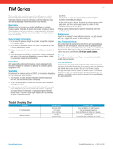
7.1 Troubleshooting
Problem / Failure Possible cause Solution
Cooling capacity not sufficient – Ambient air temperature is higher than
specified
– Select larger model
– Motor’s rotation direction wrong – Correct connection, see Electrical connec-
tions
– Motor doesn’t start – Correct connection, see Electrical connec-
tions
– Air flow too low – Correct connection, see Electrical connec-
tions
– Air fins clogged – Clean cooler matrix, see Maintenance
– Near obstacles – Regard minimum distance
– Oil flow too low – Increase oil flow
– Oil channel clogged – Cleaning, see chapter Cleaning the cooler
matrix inside
– Oil circuit blocked – Open valves and cocks
Tab.1: Troubleshooting
14 Bühler Technologies GmbH BE350025 ◦ 03/2019

BLK
8 Disposal
Dispose of the parts in such a way that does not present a danger to other people’s heath or to the environment. Observe the
legal requirements in the country of use for the disposal of electrical components and oils and coolants.
15Bühler Technologies GmbHBE350025 ◦ 03/2019

BLK
9 Appendices
9.1 Technical data
Technical Data
Materials / surface protection
Cooling battery:
ventilation box, safety guard and motor brackets:
Aluminium, painted
plastic-coated steel
Colour:
RAL 7001 / Motor: RAL 7024/7030
Operating fluids:
Mineral oils per DIN 51524
oil-/water emulsions HFA and HFB per CETOP RP 77 H
Water glycol HFC per CETOP RF 77 H
Phosphoric ester HFD-R per CETOP RP 77 H
Operating pressure
static
BLK 1.2:
BLK 2.2 – BLK 10.8:
dynamic
BLK 1.2:
BLK 2.2 – BLK 10.8:
max. 16 bar
max. 21 bar
11 bar (at 5 M load cycle, 3Hz)
15 bar (at 5 M load cycle, 3Hz)
Operating oil temperature:
max. 80 °C (higher upon request)
Ambient temperature:
-15 to 40 °C
Electric motors (others available upon request)
Voltage / frequency:
BLK 1.2:
BLK 2.2 – BLK 10.8:
230 V - 50 Hz
220/380 – 245/420V 50Hz
220/380 – 280/480V 60Hz
Thermal stability:
Class of insulation F,
utilisation per Class B
Protection class:
BLK 1.2:
BLK 2.2 – BLK 10.8:
IP44
IP55
The motors comply with standards
IEC 60034, IEC 60072, IEC 60085
16 Bühler Technologies GmbH BE350025 ◦ 03/2019

BLK
9.1.1 Basic data (at 50 Hz frequency)
Item no. Cooler type Motor power
Number of poles
Rated current at 400 V
Weight
(kg)
Capacity
(L)
Noise level
db(A)*
3501200 BLK 1.2 0,05 kW / 2 / 0,24 A (230 V) 7 0,8 65
3502200 BLK 2.2 0,55 kW / 2 / 1,4 A 23 1,3 81
3502400 BLK 2.4 0,18 kW / 4 / 0,6 A 23 1,3 66
3503200IE3 BLK 3.2 1,1 kW / 2 / 2,3 A 34 1,8 87
3503400 BLK 3.4 0,25 kW / 4 / 0,9 A 28 1,8 71
3504400 BLK 4.4 0,37 kW / 4 / 1,1 A 34 2,3 73
3504600 BLK 4.6 0,18 kW / 6 / 0,6 A 34 2,3 63
3505400IE3 BLK 5.4 0,75 kW / 4 / 1,9 A 48 3,1 79
3505600 BLK 5.6 0,25 kW / 6 / 0,9 A 42 3,1 68
3506410IE3 BLK 6.4 2,2 kW / 4 / 4,6 A 77 4,1 86
3506610 BLK 6.6 0,55 kW / 6 / 1,9 A 60 4,1 74
3507410IE3 BLK 7.4 2,2 kW / 4 / 4,6 A 88 5,4 89
3507610 BLK 7.6 0,55 kW / 6 / 1,9 A 72 5,4 75
3508610IE3 BLK 8.6 1,5 kW / 6 / 3,8 A 104 6,3 79
3508810 BLK 8.8 0,55 kW / 8 / 1,9 A 91 6,3 73
3509610IE3 BLK 9.6 2,2 kW / 6 / 5,6 A 158 8,2 86
3509810 BLK 9.8 1,1 kW / 8 / 3,2 A 155 8,2 79
3510610IE3 BLK 10.6 5,5 kW / 6 / 12,8 A 258 19 90
3510810 BLK 10.8 2,2 kW / 8 / 6 A 241 19 84
The item numbers for BLK 2.2-5.6 are 50/60 Hz versions, for BLK 6.4-10.8 only the 50 Hz version, please contact us for the 60 Hz
version.
*DIN EN ISO 3744, Class 3
17Bühler Technologies GmbHBE350025 ◦ 03/2019

BLK
9.1.2 Performance curves frame size 1-6
9.1.3 Performance curves frame size 7-10
18 Bühler Technologies GmbH BE350025 ◦ 03/2019
/