
MODELS
GWN20TB, GWP20TB, GWN30TB, GWP30TB, HDB20NT, HDB20PT,
HDB30NT, HDB30PT, MN20T, MP20T, MN30T, MP30T,
VN20BTB, VP20BTB, VN30BTB, VP30BTB WMN20A, WMP20A
UNVENTED (VENT-FREE) BLUE FLAME GAS HEATER
SAFETY INFORMATION AND INSTALLATION MANUAL
For more information, visit www.desatech.com
WARNING: If the information in this manual is not
followed exactly, a re or explosion may result causing
property damage, personal injury or loss of life.
— Do not store or use gasoline or other ammable
vapors and liquids in the vicinity of this or any other
appliance.
— WHAT TO DO IF YOU SMELL GAS
• Do not try to light any appliance.
• Do not touch any electrical switch; do not use any
phone in your building.
• Immediately call your gas supplier from a neighbor’s
phone. Follow the gas supplier’s instructions.
• If you cannot reach your gas supplier, call the re
department.
— Installation and service must be performed by a quali-
ed installer, service agency or the gas supplier.
INSTALLER: Leave this manual with the appliance.
CONSUMER: Retain this manual for future reference.

www.desatech.com
124002-01C2
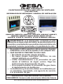
SAFETY
This appliance may be in-
stalled in an aftermarket,*
permanently located,
manufactured (mobile)
home, where not prohib-
ited by local codes.
* Aftermarket: Completion of sale, not for
purpose of resale, from the manufacturer
WARNING: This product con-
tains and/or generates chemicals
known to the State of California
to cause cancer or birth defects
or other reproductive harm.
IMPORTANT: Read this owner’s
manual carefully and completely
before trying to assemble, operate
or service this heater. Improper
use of this heater can cause seri-
ous injury or death from burns, re,
explosion, electrical shock and
carbon monoxide poisoning.
DANGER: Carbon monoxide
poisoning may lead to death!
Carbon Monoxide Poisoning: Early signs
of carbon monoxide poisoning resemble the
u, with headaches, dizziness or nausea. If
you have these signs, the heater may not be
working properly. Get fresh air at once! Have
heater serviced. Some people are more af-
fected by carbon monoxide than others. These
include pregnant women, people with heart or
lung disease or anemia, those under the inu-
ence of alcohol and those at high altitudes.
WARNING: Improper
installation, adjustment,
alteration, service or main-
tenance can cause injury
or property damage. Refer
to this manual for correct
installation and operation-
al procedures. For assis-
tance or additional infor-
mation consult a qualied
installer, service agency or
the gas supplier.
WARNING: This is an
unvented gas-red heater.
It uses air (oxygen) from the
room in which it is installed.
Provisions for adequate
combustion and ventila-
tion air must be provided.
Refer to Air for Combustion
and Ventilation section on
page 5 of this manual.
This appliance is only for
use with the type of gas
indicated on the rating
plate. This appliance is
not convertible for use
with other gases.
TABLE OF CONTENTS
Safety .................................................................. 2
Local Codes......................................................... 4
Unpacking............................................................ 4
Product Identication ........................................... 4
Product Features ................................................. 4
Air For Combustion And Ventilation ..................... 5
Installation ........................................................... 7
Operation ........................................................... 15
Inspecting Heater .............................................. 17
Cleaning and Maintenance ................................ 18
Troubleshooting ................................................. 19
Specications .................................................... 23
Replacement Parts ............................................ 23
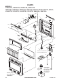
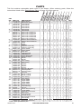
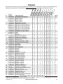
Parts .................................................................. 24
Accessories ....................................................... 26
Service Hints ..................................................... 26
Technical Service............................................... 26
Service Publications .......................................... 26
Parts Central...................................................... 27

www.desatech.com
124002-01C 3
Natural and Propane/LP Gas: Natural and
propane/LP gases are fuel gases. Fuel gases
are odorless. An odor-making agent is added
to fuel gases. The odor helps you detect a fuel
gas leak. However, the odor added to fuel
gas can fade. Fuel gas may be present even
though no odor exists.
Make certain you read and understand all
warnings. Keep this manual for reference. It
is your guide to safe and proper operation of
this heater.
WARNING: Any change to
this heater or its controls can
be dangerous.
WARNING: Do not use a
blower insert, heat exchanger
insert or other accessory not ap-
proved for use with this heater.
Due to high temperatures, the
appliance should be located out
of trafc and away from furniture
and draperies.
Do not place clothing or other
ammable material on or near
the appliance. Never place any
objects on the heater.
Surface of heater becomes very
hot when running heater. Keep
children and adults away from
hot surface to avoid burns or
clothing ignition. Heater will
remain hot for a time after shut-
down. Allow surface to cool
before touching.
Carefully supervise young chil-
dren when they are in the same
room with heater.
Make sure grill guard is in place
before running heater.
Keep the appliance area clear
and free from combustible ma-
terials, gasoline and other am-
mable vapors and liquids.
1. This appliance is only for use with the type
of gas indicated on the rating plate. This
appliance is not convertible for use with
other gases.
2. Do not place propane/LP supply tank(s)
inside any structure. Locate propane/LP
supply tank(s) outdoors.
3. This heater shall not be installed in a
bedroom or bathroom.
4. If you smell gas
• shut off gas supply
• do not try to light any appliance
• do not touch any electrical switch; do not
use any phone in your building
• immediately call your gas supplier from
a neighbor’s phone. Follow the gas sup-
plier’s instructions
• if you cannot reach your gas supplier,
call the re department
5.
This heater needs fresh, outside air ventila-
tion to run properly. This heater has an Oxy-
gen Depletion Sensing (ODS) safety shutoff
system. The ODS shuts down the heater if
not enough fresh air is available. See Air for
Combustion and Ventilation, page 5.
6. Keep all air openings in front and bottom
of heater clear and free of debris. This will
insure enough air for proper combustion.
7. If heater shuts off, do not relight until you
provide fresh, outside air. If heater keeps
shutting off, have it serviced.
8. Do not run heater
• where ammable liquids or vapors are
used or stored
• under dusty conditions
9. Before using furniture polish, wax, carpet
cleaner or similar products, turn heater off. If
heated, the vapors from these products may
create a white powder residue within burner
box or on adjacent walls or furniture.
10. Do not use heater if any part has been
under water. Immediately call a qualied
service technician to inspect the room
heater and to replace any part of the
control system and any gas control which
has been under water.
11. Turn off and let cool before servicing. Only
a qualied service person should service
and repair heater.
SAFETY
Continued

www.desatech.com
124002-01C4
12. Operating heater above elevations of
4,500 feet could cause pilot outage.
13. To prevent performance problems, do not
use propane/LP fuel tank of less than 100
lbs. capacity.
SAFETY
Continued
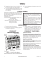
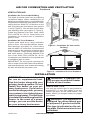
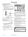
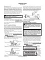
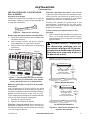
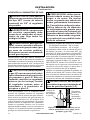
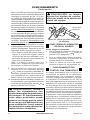
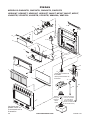
Figure 1 - Vent-Free Gas Heater
(actual heater may vary from illustration)
Ignitor Button
Control Knob
Heater
Cabinet
Front Panel
Glass Panel
Grill Guard
PRODUCT
IDENTIFICATION
PRODUCT FEATURES
SAFETY DEVICE
This heater has a pilot with an Oxygen Deple-
tion Sensing (ODS) safety shutoff system. The
ODS/pilot is a required feature for vent-free
room heaters. The ODS/pilot shuts off the
heater if there is not enough fresh air.
IGNITION SYSTEM
Some models are equipped with a piezo
ignitor that requires no matches, batteries or
other sources to light heater.
Other heaters are equipped with an electronic
ignitor to light heater fuel supply.
THERMOSTATIC HEAT CONTROL
Thermostat models have a thermostat sens-
ing bulb and a control valve. This results in the
greatest heater comfort. This can also result
in lower gas bills.
14. Provide adequate clearances around air
openings.
LOCAL CODES
Install and use heater with care. Follow all lo-
cal codes. In the absence of local codes, use
the latest edition of National Fuel Gas Code,
ANSI Z223.1/NFPA 54*.
*Available from:
American National Standards Institute, Inc.
1430 Broadway
New York, NY 10018
National Fire Protection Association, Inc.
Batterymarch Park
Quincy, MA 02269
State of Massachusetts: The installation
must be made by a licensed plumber or
gas tter in the Commonwealth of Mas-
sachusetts.
Sellers of unvented propane or natural
gas-red supplemental room heaters shall
provide to each purchaser a copy of 527
CMR 30 upon sale of the unit.
Vent-free gas products are prohibited for
bedroom and bathroom installation in the
Commonwealth of Massachusetts.
UNPACKING
1. Remove heater from carton.
2. Remove all protective packaging applied
to heater for shipment.
3. Check heater for any shipping damage.
If heater is damaged, promptly return to
dealer where you bought heater or call
DESA Heating, LLC at 1-866-672-6040.

www.desatech.com
124002-01C 5
AIR FOR COMBUSTION AND VENTILATION
Unusually Tight Construction
The air that leaks around doors and windows
may provide enough fresh air for combustion
and ventilation. However, in buildings of un-
usually tight construction, you must provide
additional fresh air.
Unusually tight construction is dened as
construction where:
a. walls and ceilings exposed to the outside
atmosphere have a continuous water
vapor retarder with a rating of one perm
(6x10
-11
kg per pa-sec-m
2
) or less with
openings gasketed or sealed and
b. weather stripping has been added on
openable windows and doors and
c. caulking or sealants are applied to areas
such as joints around window and door
frames, between sole plates and oors,
between wall-ceiling joints, between
wall panels, at penetrations for plumb-
ing, electrical and gas lines and at other
openings.
If your home meets all of the three criteria
above, you must provide additional fresh air.
See Ventilation Air From Outdoors, page 7.
If your home does not meet all of the three
criteria above, proceed to Determining Fresh-
Air Flow For Heater Location, page 6.
Conned and Unconned Space
The National Fuel Gas Code, ANSI Z223.1/
NFPA 54 denes a conned space as a space
whose volume is less than 50 cubic feet per
1,000 Btu/hr (4.8 m
3
per kw) of the aggregate
input rating of all appliances installed in that
space and an unconned space as a space
whose volume is not less than 50 cubic feet
per 1,000 Btu/hr (4.8 m
3
per kw) of the ag-
gregate input rating of all appliances installed
in that space. Rooms communicating directly
with the space in which the appliances are
installed*, through openings not furnished
with doors, are considered a part of the un-
conned space.
* Adjoining rooms are communicating only if
there are doorless passageways or ventilation
grills between them.
WARNING: This heater shall
not be installed in a room or
space unless the required vol-
ume of indoor combustion air
is provided by the method de-
scribed in the National Fuel Gas
Code, ANSI Z223.1/NFPA 54, the
International Fuel Gas Code, or
applicable local codes. Read the
following instructions to insure
proper fresh air for this and
other fuel-burning appliances
in your home.
Today’s homes are built more energy efcient
than ever. New materials, increased insulation
and new construction methods help reduce
heat loss in homes. Home owners weather
strip and caulk around windows and doors to
keep the cold air out and the warm air in. Dur-
ing heating months, home owners want their
homes as airtight as possible.
While it is good to make your home energy
efcient, your home needs to breathe. Fresh
air must enter your home. All fuel-burning ap-
pliances need fresh air for proper combustion
and ventilation.
Exhaust fans, replaces, clothes dryers and
fuel burning appliances draw air from the
house to operate. You must provide adequate
fresh air for these appliances. This will insure
proper venting of vented fuel-burning appli-
ances.
PROVIDING ADEQUATE
VENTILATION
The following are excerpts from National Fuel
Gas Code, ANSI Z223.1/NFPA 54, Air for
Combustion and Ventilation.
All spaces in homes fall into one of the three
following ventilation classications:
1. Unusually Tight Construction
2. Unconned Space
3. Conned Space
The information on pages 5 through 7 will help
you classify your space and provide adequate
ventilation.

www.desatech.com
124002-01C6
AIR FOR COMBUSTION AND VENTILATION
Continued
DETERMINING FRESH-AIR FLOW
FOR HEATER LOCATION
Determining if You Have a Conned or
Unconned Space
Use this work sheet to determine if you have a
conned or unconned space.
Space: Includes the room in which you will install
heater plus any adjoining rooms with doorless
passageways or ventilation grills between the
rooms.
1. Determine the volume of the space (length
x width x height).
Length x Width x Height =__________cu. ft.
(volume of space)
Example: Space size 20 ft. (length) x 16 ft.
(width) x 8 ft. (ceiling height) = 2560 cu. ft.
(volume of space)
If additional ventilation to adjoining room
is supplied with grills or openings, add the
volume of these rooms to the total volume
of the space.
2. Multiply the space volume by 20 to determine
the maximum Btu/Hr the space can support.
______ (volume of space) x 20 = (Maximum
Btu/Hr the space can support)
Example: 2560 cu. ft. (volume of space) x
20 = 51,200 (maximum Btu/Hr the space
can support)
3. Add the Btu/Hr of all fuel burning appliances
in the space.
Vent-free heater ____________ Btu/Hr
Gas water heater* ____________ Btu/Hr
Gas furnace ____________ Btu/Hr
Vented gas heater ____________ Btu/Hr
Gas replace logs ____________ Btu/Hr
Other gas appliances*
+ ___________ Btu/Hr
Total = ___________ Btu/Hr
* Do not include direct-vent gas appliances.
Direct-vent draws combustion air from the
outdoors and vents to the outdoors.
Example:
Gas water heater ____________ Btu/Hr
Vent-free heater + ___________ Btu/Hr
Total = ___________ Btu/Hr
40,000
20,000
60,000
4. Compare the maximum Btu/Hr the space
can support with the actual amount of Btu/
Hr used.
_______ Btu/Hr (maximum can support)
_______ Btu/Hr (actual amount used)
Example:
51,200 Btu/Hr (maximum the space can
support)
60,000 Btu/Hr (actual amount of Btu/Hr
used)
The space in the above example is a conned
space because the actual Btu/Hr used is more
than the maximum Btu/Hr the space can sup-
port. You must provide additional fresh air. Your
options are as follows:
A. Rework worksheet, adding the space of an
adjoining room. If the extra space provides
an unconned space, remove door to adjoin-
ing room or add ventilation grills between
rooms. See Ventilation Air From Inside
Building, page 7.
B. Vent room directly to the outdoors. See
Ventilation Air From Outdoors, page 7.
C. Install a lower Btu/Hr heater, if lower Btu/Hr
size makes room unconned.
If the actual Btu/Hr used is less than the maximum
Btu/Hr the space can support, the space is an
unconned space. You will need no additional
fresh air ventilation.
WARNING: If the area in which
the heater may be operated does
not meet the required volume for
indoor combustion air, combus-
tion and ventilation air shall be
provided by one of the methods
described in the National Fuel
Gas Code, ANSI Z223.1/NFPA 54,
the International Fuel Gas Code,
or applicable local codes.

www.desatech.com
124002-01C 7
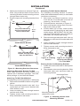
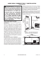
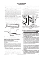
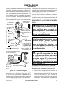
Figure 3 - Ventilation Air from Outdoors
VENTILATION AIR
Ventilation Air From Inside Building
This fresh air would come from an adjoining
unconned space. When ventilating to an
adjoining unconned space, you must provide
two permanent openings: one within 12" of the
ceiling and one within 12" of the oor on the
wall connecting the two spaces (see options
1 and 2, Figure 2). You can also remove door
into adjoining room (see option 3, Figure 2).
Follow the National Fuel Gas Code, ANSI
Z223.1/NFPA 54, Air for Combustion and
Ventilation for required size of ventilation
grills or ducts.
Ventilation Air From Outdoors
Provide extra fresh air by using ventilation
grills or ducts. You must provide two perma-
nent openings: one within 12" of the ceiling
and one within 12" of the oor. Connect these
items directly to the outdoors or spaces open
to the outdoors. These spaces include attics
and crawl spaces. Follow the National Fuel
Gas Code, ANSI Z223.1/NFPA 54, Air for
Combustion and Ventilation for required size
of ventilation grills or ducts.
IMPORTANT: Do not provide openings for
inlet or outlet air into attic if attic has a thermo-
stat-controlled power vent. Heated air entering
the attic will activate the power vent.
Figure 2 - Ventilation Air from Inside
Building
Or
Remove
Door into
Adjoining
Room,
Option 3
Ventilation Grills
Into Adjoining Room,
Option 2
12"
12"
Ventilation
Grills into
Adjoining
Room,
Option 1
Outlet
Air
Ventilated
Attic
Outlet
A
ir
Inlet
Air
Inlet Air
V e ntilated
Crawl Space
T o
Crawl
Space
T o A ttic
AIR FOR COMBUSTION AND VENTILATION
Continued
INSTALLATION
NOTICE: This heater is intended
for use as supplemental heat.
Use this heater along with your
primary heating system. Do not
install this heater as your pri-
mary heat source. If you have a
central heating system, you may
run system’s circulating blower
while using heater. This will help
circulate the heat throughout the
house. In the event of a power
outage, you can use this heater
as your primary heat source.
WARNING: A qualied ser-
vice person must install heater.
Follow all local codes.
CHECK GAS TYPE
Use only the correct type of gas (natural or
propane/LP). If your gas supply is not the
correct gas type, do not install heater. Call
dealer where you bought heater for proper
type heater.
WARNING: This appliance is
equipped for either natural gas
or propane/LP gas but not both.
Gas type is indicated on the rat-
ing plate. Field conversion is not
permitted.

www.desatech.com
124002-01C8
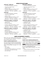
INSTALLATION ITEMS
Before installing heater, make sure you have
the items listed below.
• for propane/LP gas, external regulator
(supplied by installer)
• piping (check local codes)
• sealant (resistant to propane/LP gas)
• equipment shutoff valve *
• ground joint union
• sediment trap
• tee joint
• pipe wrench
• for natural gas, test gauge connection*
• hardware packet (included)
- wall anchor (4) 095112-02
- red key (1) 095116-01
- pan head screw, black (4) 097403-02
- nylon spacer (2) 099064-02
- clamp (1) 099123-01
- Phillips head screw, silver (4) 100159-02
* A CSA design-certied equipment shutoff
valve with 1/8" NPT tap is an acceptable alter-
native to test gauge connection. The optional
CSA design-certied equipment shutoff valve
can be purchased from your dealer.
LOCATING HEATER
This heater is designed to be mounted on a wall.
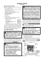
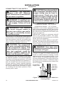
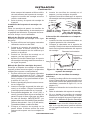
WARNING: Maintain the
minimum clearances shown
in Figure 4. If you can, provide
greater clearances from oor,
ceiling and joining wall.
You can locate heater on oor, away from
a wall. An optional oor mounting stand is
needed. Purchase the oor mounting stand
from your dealer. See Accessories, page 26,
if stand is not included with your heater.
WARNING: Never install the
heater
• in a bedroom or bathroom
• in a recreational vehicle
• where curtains, furniture, cloth-
ing or other ammable objects
are less than 36" from the front,
top or sides of heater
• as a replace insert
• in high trafc areas
• in windy or drafty areas
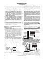
Figure 4 - Mounting Clearances As
Viewed From Front of Heater
INSTALLATION
Continued
CAUTION: This heater creates
warm air currents. These currents
move heat to wall surfaces next
to heater. Installing heater next
to vinyl or cloth wall coverings or
operating heater where impurities
(such as, but not limited to, to-
bacco smoke, aromatic candles,
cleaning uids, oil or kerosene
lamps, etc.) in the air exist, may
discolor walls or cause odors.
IMPORTANT: Vent-free heaters add moisture
to the air. Although this is benecial, installing
heater in rooms without enough ventilation
air may cause mildew to form from too much
moisture. See Air for Combustion and Ventila-
tion, page 5. If high humidity is experienced,
a dehumidier may be used to help lower the
water vapor content in the air.
CAUTION: If you install the
heater in a home garage
• heater pilot and burner must
be at least 18" above oor
• locate heater where moving
vehicle will not hit it
For convenience and efciency, install heater
• where there is easy access for operation,
inspection and service
• in coldest part of room
If not included with your heater, an optional fan
kit is available from your dealer. See Acces-
sories, page 26. If planning to use fan, locate
heater near an electrical outlet (see page 16).
Minimum
From
Sides Of
Heater
36"
2"
FLOOR
CEILING
Minimum
Minimum To
Top Surface
Of Carpeting,
Tile Or Other
Combustible
Material
Left
Side
Right
Side
6"
36"
(91.5 cm)

www.desatech.com
124002-01C 9
INSTALLATION
Continued
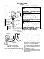
THERMOSTAT SENSING BULB
(Thermostat Models Only)
The thermostat sensing bulb has been placed
below the heater.
1. Place clamp on thermostat sensing bulb
as shown in Figure 5. Clamp is provided
in hardware package.
2. Snap clamp into upper mounting hole as
shown in Figure 5. Mounting hole is located
on lower left edge on back of heater. Make
sure the thermostat sensing bulb is point-
ing up.
Figure 5 - Attaching Thermostat Sensing
Bulb
INSTALLING HEATER TO WALL
Mounting Bracket
Locate mounting bracket in heater carton. Re-
move mounting bracket from heater carton.
Figure 7 - Removing Front Panel Of Heater
(actual heater may vary from illustration)
Clamp
Thermostat
Sensing Bulb
Figure 6 - Mounting Bracket
Removing Front Panel Of Heater
1. Remove the four painted screws, two on
each side of front panel.
2. Pull bottom of front panel forward, then
out.
3. Remove any remaining packaging ma-
terials.
Methods For Attaching Mounting Bracket
To Wall
Only use last hole on each end of mounting
bracket to attach bracket to wall. These two
holes are 14" apart from their centers. Attach
mounting bracket to wall in one of two ways:
1. Attaching to wall stud
2. Attaching to wall anchor
Attaching to Wall Stud: This method pro-
vides the strongest hold. Insert mounting
screws through mounting bracket and into
wall studs.
Attaching to Wall Anchor: This method al-
lows you to attach mounting bracket to hollow
walls (wall areas between studs) or to solid
walls (concrete or masonry).
Decide which method better suits your needs.
Either method will provide a secure hold for
the mounting bracket.
Marking Screw Locations
1. Tape mounting bracket to wall where
heater will be located. Make sure mount-
ing bracket is level.
WARNING: Maintain mini-
mum clearances shown in Figure
8, page 10. If you can, provide
greater clearances from oor
and joining wall.
Screw
Front Panel

www.desatech.com
124002-01C10
16"
Min.
14"
12"
Min.
Adjoining Wall
14"
Adjoining Wall
Only Insert Mounting
Screws Through Last
Hole On Each End
Only Insert Mounting
Screws Through Last
Hole On Each End
Floor
Floor
19
3
/
4
"
Min.
19
3
/
4
"
Min.
INSTALLATION
Continued
20,000 Btu/Hr Models
30,000 Btu/Hr Models
Figure 8 - Mounting Bracket Clearances
Attaching Mounting Bracket To Wall
Note: Wall anchors, mounting screws and
spacers are in hardware package. The hard-
ware package is provided with heater.
Attaching To Wall Stud Method
For attaching mounting bracket to wall studs
1. Drill holes at marked locations using 9/64"
drill bit.
2. Place mounting bracket onto wall. Line
up last hole on each end of bracket with
holes drilled in wall.
3. Insert mounting screws through bracket
and into wall studs.
4. Tighten screws until mounting bracket is
rmly fastened to wall studs.
Figure 9 - Folding
Anchor
Figure 11 - Mounting Heater Onto
Mounting Bracket
Stand-
Out Tab
Figure 10 - Popping
Open Anchor Wings
For Thin Walls
Mounting Bracket
(attached to wall)
Horizontal Slots
Attaching To Wall Anchor Method
For attaching mounting bracket to hollow
walls (wall areas between studs) or solid walls
(concrete or masonry)
1. Drill holes at marked locations using
5/16" drill bit. For solid walls (concrete or
masonry), drill at least 1" deep.
2. Fold wall anchor as shown in Figure 9.
3. Insert wall anchor (wings rst) into hole.
Tap anchor ush to wall.
4. For thin walls (1/2" or less), insert red key
into wall anchor. Push red key to “pop” open
anchor wings. IMPORTANT: Do not ham-
mer key! For thick walls (over 1/2" thick) or
solid walls, do not pop open wings.
5. Place mounting bracket onto wall. Line up
last hole on each end of bracket with wall
anchors.
6. Insert mounting screws through bracket
and into wall anchors.
7. Tighten screws until mounting bracket is
rmly fastened to wall.
2.
Mark screw locations on wall (see Figure 8).
Note: Only mark last hole on each end of
mounting bracket. Insert mounting screws
through these holes only.
3. Remove tape and mounting bracket from
wall.
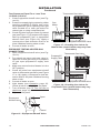
Placing Heater On Mounting Bracket
1. Locate two horizontal slots on back panel
of heater.
2. Place heater onto mounting bracket. Slide
horizontal slots onto stand-out tabs on
mounting bracket.

www.desatech.com
124002-01C 11
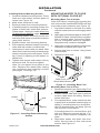
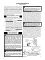
Figure 12 - Installing Bottom Mounting
Screws
Side View
Front View
Wall
Spacer
Heater
Installing Bottom Mounting Screws
1. Locate two bottom mounting holes. These
holes are near bottom on back panel of
heater (see Figure 12).
2. Mark screw locations on wall.
3. Remove heater from mounting bracket.
4. If installing bottom mounting screws into
hollow or solid wall, install wall anchors.
Follow steps 1 through 4 under Attaching
To Wall Anchor Method, page 10.
If installing bottom mounting screw into
wall stud, drill holes at marked locations
using 9/64" drill bit.
5. Replace heater onto mounting bracket.
6. Place spacers between bottom mounting
holes and wall anchor or drilled hole.
7. Hold spacer in place with one hand. With
other hand, insert mounting screw through
bottom mounting hole and spacer. Place
tip of screw in opening of wall anchor or
drilled hole.
8. Tighten both screws until heater is rmly
secured to wall. Do not over tighten.
Note: Do not replace front panel at this
time. Replace front panel after making
gas connections and checking for leaks
(see pages 12 through 14).
INSTALLATION
Continued
MOUNTING HEATER TO FLOOR
WITH OPTIONAL FLOOR KIT
Mounting Base Feet to Heater
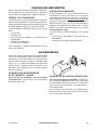
Note: A 90° elbow is required for mounting this
unit and must be installed BEFORE base feet
to provide proper clearance (see Figure 15).
1. Lay heater cabinet on its back on a table
with the heater bottom overhanging table
edge.
2. Apply pipe joint sealant lightly to male NPT
threads of elbow. Hold pressure regulator
with a wrench when connecting elbow.
Do not overtighten elbow to regulator.
Regulator body could be damaged.
3. Align holes in base foot with mounting holes
on bottom of cabinet (see Figure 13).
4. Secure base foot to heater using sheet
metal screws.
5. Repeat for other side.
Figure 13 - Installing Base Feet
Sheet Metal Screw
Wood
Screw
Base Foot
Mounting Base Feet to Floor
1. Remove front panel (see Removing Front
Panel of Heater, page 9).
2. Position heater with base feet in desired
location. Mark holes for drilling. Remove
heater with base.
3. For carpeted oors, make a small cut with
a sharp knife at marked locations prior to
drilling. If mounting base to a wood oor,
drill 1/8" diameter hole, 3/4" deep. (Do not
use anchors in wood oors).
If mounting base to a concrete oor, drill
with 1/4" diameter concrete drill bit, 1
3
/8"
into oor. Insert anchors completely into
holes.
4. Reposition heater with base feet over
holes. Secure base to oor with wood
screws. See Figure 13.

www.desatech.com
124002-01C12
CONNECTING TO GAS SUPPLY
WARNING: This appliance
requires a 3/8" NPT (National
Pipe Thread) inlet connection to
the pressure regulator.
WARNING: A qualied ser-
vice person must connect heater
to gas supply. Follow all local
codes.
WARNING: For natural
gas, never connect heater to
private (non-utility) gas wells.
This gas is commonly known
as wellhead gas.
IMPORTANT: For natural gas, check gas line
pressure before connecting heater to gas line.
Gas line pressure must be no greater than
10.5" of water. If gas line pressure is higher,
heater regulator damage could occur.
CAUTION: For propane/LP
gas, never connect heater directly
to the propane/LP supply. This
heater requires an external regu-
lator (not supplied). Install the
external regulator between the
heater and propane/LP supply.
For propane/LP gas, the installer must supply
an external regulator. The external regulator
will reduce incoming gas pressure. You must
reduce incoming gas pressure to between 11"
and 14" of water. If you do not reduce incom-
ing gas pressure, heater regulator damage
could occur. Install the external regulator with
the vent pointing down as shown in Figure
14. Pointing the vent down protects it from
freezing rain or sleet.
INSTALLATION
Continued
Figure 14 - External Regulator With Vent
Pointing Down
External
Regulator
With Vent
Pointing
Down
Propane/LP
Supply Tank
CAUTION: Use only new, black
iron or steel pipe. Internally-tinned
copper tubing may be used in
certain areas. Check your local
codes. Use pipe of large enough
diameter to allow proper gas vol-
ume to heater. If pipe is too small,
undue loss of volume will occur.
Typical Inlet Pipe Diameters
20,000 Btu/Hr Models - 3/8" or greater
30,000 Btu/Hr Models - 1/2" or greater
Installation must include equipment shutoff
valve, union and plugged 1/8" NPT tap. Locate
NPT tap within reach for test gauge hook up.
NPT tap must be upstream from heater (see
Figure 15, page 13).
IMPORTANT: Install an equipment shutoff
valve in an accessible location. The equip-
ment shutoff valve is for turning on or shutting
off the gas to the appliance.
Apply pipe joint sealant lightly to male NPT
threads. This will prevent excess sealant from
going into pipe. Excess sealant in pipe could
result in clogged heater valves.
WARNING: Use pipe joint
sealant that is resistant to liquid
petroleum (LP) gas.
Install sediment trap in supply line as shown
in Figure 15, page 13. Locate sediment trap
where it is within reach for cleaning. Locate
sediment trap where trapped matter is not
likely to freeze. A sediment trap traps mois-
ture and contaminants. This keeps them from
going into heater controls. If sediment trap is
not installed or is installed wrong, heater may
not run properly.

www.desatech.com
124002-01C 13
* A CSA design-certied equipment shutoff
valve with 1/8" NPT tap is an acceptable al-
ternative to test gauge connection. Purchase
the optional CSA design-certied equipment
shutoff valve from your dealer.
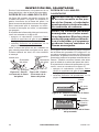
Tee Joint
Reducer
Bushing to
1/8" NPT
1/8" NPT
Plug Tap
Test Gauge Connection*
3/8" NPT
Pipe Nipple
Heater
Cabinet
Equipment
Shutoff
Valve*
3"
Min.
Natural Gas
From Gas
Meter
(4" W.C. to
10.5" W.C. Pressure)
Propane/LP
From External Regulator
(11" W.C. to 14" W.C.
Pressure)
Ground Joint
Union
IMPORTANT: Hold the pressure regulator
with wrench when connecting it to gas pip-
ing and/or ttings. Do not over tighten pipe
connection to regulator. The regulator body
could be damaged.
Tee Joint
Pipe
Nipple
Cap
Sediment Trap
INSTALLATION
Continued
CHECKING GAS CONNECTIONS
WARNING: Test all gas piping
and connections, internal and
external to unit, for leaks after
installing or servicing. Correct
all leaks at once.
WARNING: Never use an
open ame to check for a leak.
Apply a noncorrosive leak detec-
tion uid to all joints. Bubbles
forming show a leak. Correct all
leaks at once.
CAUTION: For propane/LP
gas, make sure external regula-
tor has been installed between
propane/LP supply and heater.
See guidelines under Connect-
ing to Gas Supply, page 12.
PRESSURE TESTING GAS SUPPLY
PIPING SYSTEM
Test Pressures In Excess Of 1/2 PSIG
(3.5 kPa)
1. Disconnect appliance with its appliance
main gas valve (control valve) and equip-
ment shutoff valve from gas supply piping
system. Pressures in excess of 1/2 psig
will damage heater regulator.
2. Cap off open end of gas pipe where equip-
ment shutoff valve was connected.
3. Pressurize supply piping system by either
opening propane/LP supply tank valve
for propane/LP gas or opening main gas
valve located on or near gas meter for
natural gas or using compressed air.
4. Check all joints of gas supply piping sys-
tem. Apply a noncorrosive leak detection
uid to all joints. Bubbles forming show a
leak.
5. Correct all leaks at once.
6. Reconnect heater and equipment shutoff
valve to gas supply. Check reconnected
ttings for leaks.
Figure 15 - Gas Connection
Pressure
Regulator
Connection Using Flexline
3/8" NPT/
1/2" Flare
90° Elbow
Flexline
See
illustration
above for
detail
Refer to connector's
instructions

www.desatech.com
124002-01C14
Test Pressures Equal To or Less Than
1/2 PSIG (3.5 kPa)
1. Close equipment shutoff valve (see Fig-
ure 16).
2. Pressurize supply piping system by either
opening propane/LP supply tank valve
for propane/LP gas or opening main gas
valve located on or near gas meter for
natural gas or using compressed air.
3. Check all joints from gas meter for natural
gas (see Figure 17) or propane/LP supply
tank for propane/LP gas, to equipment
shutoff valve (see Figure 18). Apply a
noncorrosive leak detection uid to all
joints. Bubbles forming show a leak.
4. Correct all leaks at once.
PRESSURE TESTING HEATER GAS
CONNECTIONS
1. Open equipment shutoff valve (see Fig-
ure 16).
2. For natural gas open main gas valve lo-
cated on or near gas meter. For propane/
LP gas open propane/LP supply tank
valve.
3. Make sure control knob of heater is in the
OFF position.
4. Check all joints from equipment shutoff
valve to thermostat gas valve (see Figure
17 or 18). Apply a noncorrosive leak de-
tection uid to all joints. Bubbles forming
show a leak.
5. Correct all leaks at once.
6. Light heater (see Operation, page 15).
Check all other internal joints for leaks.
7. Turn off heater (see To Turn Off Gas to
Appliance, page 16).
8. Replace front panel.
Figure 18 - Checking Gas Joints for
Propane/LP Gas (actual heater may vary
from illustration)
Equipment Shutoff Valve
Propane/LP
Supply Tank
Thermostat Gas Valve
Figure 17 - Checking Gas Joints for
Natural Gas (actual heater may vary from
illustration)
Equipment Shutoff Valve
Gas
Meter
Thermostat Gas Valve
INSTALLATION
Continued
Figure 16 - Equipment Shutoff Valve
Open
Closed
Equipment
Shutoff Valve

www.desatech.com
124002-01C 15
6. Thermostat Models: Turn control knob
counterclockwise to the PILOT
position. Press in control knob for ve (5)
seconds.
Manual Models: Press in and turn control
knob counterclockwise to the PILOT
position. Keep control knob pressed in for
ve (5) seconds.
7. With control knob pressed in, push down
and release ignitor button. This will light
pilot. The pilot is attached to the front of
burner. Note: You may be running this
heater for the rst time after hooking up to
gas supply. If so, you may need to press in
control knob for 30 seconds or more. This
will allow air to bleed from the gas system.
If needed, keep pressing ignitor button until
pilot lights. If ignitor does not light pilot, re-
fer to Troubleshooting, page 19 or contact a
qualied service person or gas supplier for
repairs. Until repairs are made, light pilot
with match. To light pilot with match, see
Manual Lighting Procedure, page 16.
8. Keep control knob pressed in for 30 sec-
onds after lighting pilot. After 30 seconds,
release control knob.
• If control knob does not pop up when
released, contact a qualified service
person or gas supplier for repairs.
Note: If pilot goes out, repeat steps 4 thru
7. Wait one (1) minute before lighting pilot
again.
9. Turn control knob counterclockwise
to desired heating level. The main burner
should light. Manual control heaters
should be used in locked positions.
10. To shut off burner only and leave pilot lit,
turn control knob clockwise to the
PILOT position.
OPERATION
Figure 19 - Control Knob In The OFF
Position Manual Control Models
O
F
F
I
L
O
T
Figure 20 - Control Knob In The OFF
Position Thermostat Models
FOR YOUR SAFETY READ
BEFORE LIGHTING
WARNING: If you do not fol-
low these instructions exactly,
a re or explosion may result
causing property damage, per-
sonal injury or loss of life.
A. This appliance has a pilot which must
be lighted by hand. When lighting the pi-
lot, follow these instructions exactly.
B. BEFORE LIGHTING smell all around
the appliance area for gas. Be sure to
smell next to the oor because some
gas is heavier than air and will settle
on the oor.
WHAT TO DO IF YOU SMELL GAS
• Do not try to light any appliance.
• Do not touch any electric switch; do
not use any phone in your building.
• Immediately call your gas supplier
from a neighbor’s phone. Follow the
gas supplier’s instructions.
• If you cannot reach your gas supplier,
call the re department.
C. Use only your hand to push in or turn
the gas control knob. Never use tools.
If the knob will not push in or turn by
hand, don’t try to repair it, call a qualied
service technician. Force or attempted
repair may result in a re or explosion.
D. Do not use this appliance if any part
has been under water. Immediately call
a qualied service technician to inspect
the appliance and to replace any part of
the control system and any gas control
which has been under water.
LIGHTING
INSTRUCTIONS
1.
STOP! Read the safety information above.
2. Make sure equipment shutoff valve is fully
open.
3. Turn off any electric power to the appli-
ance if service is to be performed.
4. Turn control knob clockwise to the
OFF position.
5. Wait ve minutes to clear out any gas.
Then smell for gas, including near the
oor. If you smell gas, STOP! Follow “B” in
the safety information above. If you don’t
smell gas, go to the next step.

www.desatech.com
124002-01C16
OPERATION
Continued
Note: The thermostat sensing bulb measures
the temperature of air near the heater cabinet.
This may not always agree with room tem-
perature (depending on housing construction,
installation location, room size, open air tem-
peratures, etc.). Frequent use of your heater will
let you determine your own comfort levels.
MANUAL LIGHTING
PROCEDURE
1.
Remove front panel (see Figure 7, page 9).
2. Follow steps 1 through 7 under Lighting
Instructions, page 15.
3. With control knob pressed in, strike match.
Hold match to pilot until pilot lights.
4. Keep control knob pressed in for 30 sec-
onds after lighting pilot. After 30 seconds,
release control knob. Now follow step 9,
under Lighting Instructions, page 15.
5. Replace front panel.
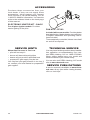
BLOWER
OPERATION
WARNING: Blower accessory
must be grounded. Blower comes
with a three-prong, grounding
plug as shown in Figure 22. The
plug is your protection against
electrical shock. Plug it into a
standard, three-hole, grounded,
outlet. If cord needs replacing,
use only a cord with a three-
prong, grounding plug.
CAUTION: Label all wires
prior to disconnection when
servicing controls. Wiring errors
can cause improper and danger-
ous operation.
CAUTION: Do not plug power
cord into electrical outlet until
installation is complete.
Figure 21 - Pilot (actual pilot may vary)
WARNING: Always operate
manual control heaters at the
locked positions. Operation
between these positions may
create a possible health hazard
if used in a poorly ventilated
room. Read owner’s manual for
complete instructions.
CAUTION: Do not try to ad-
just heating levels by using the
equipment shutoff valve.
TO TURN OFF GAS
TO APPLIANCE
Shutting Off Heater
1. Turn control knob clockwise to the
OFF position.
2. Turn off all electric power to the appliance
if service is to be performed.
3. Close equipment shutoff valve (see Figure
16, page 14).
THERMOSTAT CONTROL
OPERATION
The thermostatic control used on these
models differs from standard thermostats.
Standard thermostats simply turn on and off
the burner. The thermostat used on this heater
senses the room temperature. The thermostat
adjusts the amount of gas ow to the burner.
This increases or decreases the burner ame
height. At times the room may exceed the
set temperature. If so, the burner will shut
off. The burner will cycle back on when room
temperature drops below the set temperature.
The control knob can be set to any heat level
between 1 and 5. Selecting the 5 setting will
cause the burner to remain fully on without
modulating down in most cases.
Thermocouple
Ignitor Electrode
Pilot Burner
Grounded
Outlet
Figure 22 - Grounding Plug

www.desatech.com
124002-01C 17
OPERATION
Continued
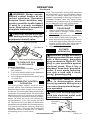
BURNER FLAME PATTERN
WARNING: If yellow tipping
occurs, your heater could pro-
duce increased levels of carbon
monoxide.
NOTICE: Do not mistake orange
ames with yellow tipping. Dirt
or other ne particles enter the
heater and burn causing brief
patches of orange ame.
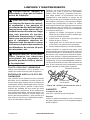
Figure 26 shows a correct burner ame pattern.
Figure 27 shows an incorrect burner ame pat-
tern. The incorrect burner ame pattern shows
yellow tipping of the ame. It also shows the
ame higher than 1/2 the glass panel height.
If burner ame pattern is incorrect, as shown
in Figure 27
• turn heater off (see To Turn Off Gas To
Appliance, page 16)
• see Troubleshooting, page 19
INSPECTING HEATER
Figure 25 - Incorrect Pilot Flame Pattern
Figure 24 - Correct Pilot Flame Pattern
Figure 26 - Correct Burner Flame Pattern
Yellow
Tipping
Figure 27 - Incorrect Burner Flame Pattern
1
/2 Glass
Height
1
/2 Glass
Height
Blue
Flame
Check pilot ame pattern and burner ame
pattern often.
PILOT FLAME PATTERN
Figure 24 shows a correct pilot ame pattern.
Figure 25 shows an incorrect pilot ame pat-
tern. The incorrect pilot ame is not touching
the thermocouple. This will cause the thermo-
couple to cool. When the thermocouple cools,
the heater will shut down.
If pilot ame pattern is incorrect, as shown
in Figure 25
• turn heater off (see To Turn Off Gas to Ap-
pliance, page 16)
• see Troubleshooting, page 19
Note: The pilot ame on natural gas units will
have a slight curve, but ame should be blue
and have no yellow or orange color.
Thermocouple
Pilot Burner
Pilot Burner
Thermocouple
Blue Flame
Yellow Flame
Extension Cord
Use extension cord if needed. The cord must
have a three-prong, grounding plug and a
three-hole receptacle. Make sure cord is in
good shape. It must be heavy enough to carry
the current needed. An undersized cord will
cause a drop in line voltage. This will result in
loss of power and overheating. Use a No. 16
AWG cord for lengths less than 50 feet.
CAUTION: Verify proper op-
eration after servicing.
Operating Blower
The blower is connected to a thermostat. When
unit heats up, the blower will operate. A few
Figure 23 - Wiring Diagram For Blower
Accessory
Thermostat
Sensor
Switch
Green
White
Green
White
1 1 0/115
V. A.C.
Blower
Motor
Black
Black
minutes after unit cycles off or is turned off,
blower will shut off. Blower will cycle on and off
in this manner. Note: If you have a heater with
a thermostat, the heater and blower will not turn
off and on at exactly the same time. Blower cycle
times will vary with heat setting selected.

www.desatech.com
124002-01C18
CLEANING AND MAINTENANCE
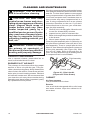
Figure 28 - Pilot Inlet Air
(Propane/LP Pilot Shown)
We also recommend that you keep the burner
tube and pilot assembly clean and free of dust
and dirt. To clean these parts we recommend
using compressed air no greater than 30 PSI.
Your local computer store, hardware store or
home center may carry compressed air in a
can. If using compressed air in a can, please
follow the directions on the can. If you don’t
follow directions on the can, you could dam-
age the pilot assembly.
1. Shut off unit, including pilot. Allow the unit
to cool for at least thirty minutes.
2. Inspect burner, pilot for dust and dirt.
3. Blow air through the ports/slots and holes
in the burner.
4. Never insert objects into the pilot tube.
Clean the pilot assembly also. A yellow tip on
the pilot ame indicates dust and dirt in the
pilot assembly. There is a small pilot air inlet
about 2" from where the pilot ame comes out
of the pilot assembly (see Figure 28). With
the unit off, lightly blow air through the air
inlet. You may blow through a drinking straw
if compressed air is not available.
CABINET
Air Passageways
Use pressurized air to clean.
Exterior
Use a soft cloth dampened with a mild soap
and water mixture. Wipe the cabinet to re-
move dust.
WARNING: Turn off heater
and let cool before cleaning.
CAUTION: You must keep
control areas, burner and circu-
lating air passageways of heater
clean. Inspect these areas of
heater before each use. Have
heater inspected yearly by a
qualied service person. Heater
may need more frequent clean-
ing due to excessive lint from
carpeting, bedding material, pet
hair, etc.
WARNING: Failure to keep
the primary air opening(s) of
the burner(s) clean may result in
sooting and property damage.
ODS/PILOT AND BURNER
Use a vacuum cleaner, pressurized air or
small, soft bristled brush to clean.
BURNER PILOT AIR INLET
The primary air inlet holes allow the proper
amount of air to mix with the gas. This pro-
vides a clean burning ame. Keep these holes
clear of dust, dirt and lint. Clean these air inlet
holes prior to each heating season. Blocked
air holes will create soot. We recommend that
you clean the unit every three months during
operation and have heater inspected yearly
by a qualied service person.
Pilot Assembly
Pilot Air Inlet

www.desatech.com
124002-01C 19
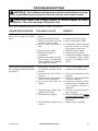
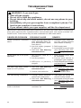
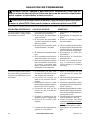
TROUBLESHOOTING
WARNING: Turn off and unplug heater and let cool before servicing.
Only a qualied service person should service and repair heater.
CAUTION: Never use a wire, needle or similar object to clean
ODS/pilot. This can damage ODS/pilot unit.
Note: All troubleshooting items are listed in order of operation.
POSSIBLE CAUSE
1. Ignitor electrode positioned
wrong
2. Ignitor electrode broken
3. Ignitor electrode not con-
nected to ignitor cable
4. Ignitor cable pinched or
wet
5. Broken ignitor cable
6. Bad piezo ignitor (if
equipped)
7. Battery not installed in elec-
tronic ignitor (if equipped),
battery power low or battery
not installed correctly
1. Gas supply turned off or
equipment shutoff valve
closed
2. Control knob not in PILOT
position
3. Control knob not pressed in
while in PILOT position
4. Air in gas lines when in-
stalled
5. Depleted gas supply (pro-
pane/LP gas only)
6. ODS/pilot is clogged
7. Gas regulator setting is not
correct
OBSERVED PROBLEM
When ignitor button is pressed,
there is no spark at ODS/
pilot
When ignitor button is pressed,
there is spark at ODS/pilot but
no ignition
REMEDY
1. Replace pilot assembly
2. Replace pilot assembly
3. Reconnect ignitor cable
4. Free ignitor cable if pinched
by any metal or tubing.
Keep ignitor cable dry
5. Replace ignitor cable
6. Replace piezo ignitor
7. Install new alkaline battery
in electronic ignitor. Verify
battery is installed cor-
rectly
1. Turn on gas supply or open
equipment shutoff valve
2. Turn control knob to PILOT
position
3. Press in control knob while
in PILOT position
4. Continue holding down
control knob. Repeat ignit-
ing operation until air is
removed
5. Contact local propane/LP
gas company
6. Clean ODS/pilot (see Clean-
ing and Maintenance, page
18) or replace ODS/pilot
assembly
7. Replace gas regulator

www.desatech.com
124002-01C20
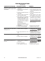
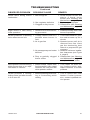
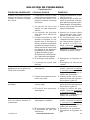
OBSERVED PROBLEM
ODS/pilot lights but flame
goes out when control knob
is released
Burner does not light after
ODS/pilot is lit
Delayed ignition of burner
Burner backring during com-
bustion
REMEDY
1. Press in control knob fully
2. After ODS/pilot lights, keep
control knob pressed in 30
seconds
3. Fully open equipment shut-
off valve
4. Hand tighten until snug,
then tighten 1/4 turn more
5. A) Contact local natural or
propane/LP gas company
B) Clean ODS/pilot (see
Cleaning and Maintenance,
page 18) or replace ODS/
pilot assembly
6. Replace pilot assembly
7. Replace control valve
1. Clean burner (see Cleaning
and Maintenance, page 18)
or replace burner orice
2. Contact local natural or
propane/LP gas company
1. Contact local natural or
propane/LP gas company
2. Clean burner (see Cleaning
and Maintenance, page 18)
or replace burner orice
1. Clean burner (see Cleaning
and Maintenance, page 18)
or replace burner orice
2. Replace burner
3. Replace gas regulator
POSSIBLE CAUSE
1. Control knob not fully
pressed in
2. Control knob not pressed in
long enough
3. Equipment shutoff valve not
fully open
4. Thermocouple connection
loose at control valve
5. Pilot flame not touching
thermocouple, which al-
lows thermocouple to cool,
causing pilot ame to go
out. This problem could be
caused by one or both of
the following:
A) Low gas pressure
B) Dirty or partially clogged
ODS/pilot
6. Thermocouple damaged
7. Control valve damaged
1. Burner orice is clogged
2. Inlet gas pressure is too
low
1. Manifold pressure is too
low
2. Burner orice is clogged
1. Burner orice is clogged or
damaged
2. Burner damaged
3. Gas regulator defective
TROUBLESHOOTING
Continued
Page is loading ...
Page is loading ...
Page is loading ...
Page is loading ...
Page is loading ...
Page is loading ...
Page is loading ...
Page is loading ...
Page is loading ...
Page is loading ...
Page is loading ...
Page is loading ...
Page is loading ...
Page is loading ...
Page is loading ...
Page is loading ...
Page is loading ...
Page is loading ...
Page is loading ...
Page is loading ...
Page is loading ...
Page is loading ...
Page is loading ...
Page is loading ...
Page is loading ...
Page is loading ...
Page is loading ...
Page is loading ...
Page is loading ...
Page is loading ...
Page is loading ...
Page is loading ...
Page is loading ...
Page is loading ...
Page is loading ...
Page is loading ...
Page is loading ...
Page is loading ...
Page is loading ...
Page is loading ...
-
 1
1
-
 2
2
-
 3
3
-
 4
4
-
 5
5
-
 6
6
-
 7
7
-
 8
8
-
 9
9
-
 10
10
-
 11
11
-
 12
12
-
 13
13
-
 14
14
-
 15
15
-
 16
16
-
 17
17
-
 18
18
-
 19
19
-
 20
20
-
 21
21
-
 22
22
-
 23
23
-
 24
24
-
 25
25
-
 26
26
-
 27
27
-
 28
28
-
 29
29
-
 30
30
-
 31
31
-
 32
32
-
 33
33
-
 34
34
-
 35
35
-
 36
36
-
 37
37
-
 38
38
-
 39
39
-
 40
40
-
 41
41
-
 42
42
-
 43
43
-
 44
44
-
 45
45
-
 46
46
-
 47
47
-
 48
48
-
 49
49
-
 50
50
-
 51
51
-
 52
52
-
 53
53
-
 54
54
-
 55
55
-
 56
56
-
 57
57
-
 58
58
-
 59
59
-
 60
60


Ask a question and I''ll find the answer in the document
Finding information in a document is now easier with AI
in other languages
- español: Desa GWP30TB Manual de usuario
Related papers
-
Desa VN6D User manual
-
Desa HDB30PT Owner's manual
-
Desa Tech RCP25 Owner's manual
-
FMI UNVENTED (VENT-FREE) NATURAL GAS LOG HEATER Owner's manual
-
FMI GCP10TGCN20T User manual
-
Comfort Glow CGCFTP CGCFTN User manual
-
Desa LSFG20NT User manual
-
-
-
Comfort Glow CRL2718N User manual
Other documents
-
Empire HB30MN-1 Owner's manual
-
Empire Comfort Systems HR30MN Installation guide
-
-
FMI GWRP16TB User manual
-
Pleasant Hearth VFL2-MO30DR User manual
-
FMI VN30BTB User manual
-
Dyna-Glo IBF10PMDG Installation guide
-
World Marketing of America GCH480 and User manual
-
-
Enerco HSVFB10LPT Operating instructions