Page is loading ...

6
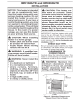
VENTILATION AIR
Ventilation Air From Outdoors
Provide extra fresh air by using
ventilation grills or ducts: You must
provide two permanent openings: one
within 12
" of the ceiling and one within
12
" of the floor.
Connect these items directly to the
outdoors or spaces open to the outdoors.
These spaces include attics and crawl
spaces. Follow the
National Fuel Gas
Code NFPA 54/ANS Z223.1, Section 5.3.
Air for Combustion and Ventilation
for
required size of ventilation grills or ducts.
IMPORTANT: Do not provide openings
for inlet or outlet air into attic if attic has
a thermostat-controlled power vent.
Heated air entering the attic will activate
the power vent.
NOTICE: This heater is
intended for use as supplemental
heat. Use this heater along with
your primary heating system. Do
not install this heater. as your
primary heat source. If you have
a central heating system, you
may run system’s circulating
blower while using heater. This
will help circulate the heat
throughout the house. In the
event of a power outage, you can
use this heater as your primary
heat source.
WARNING: A qualified
service person must install
heater. Follow all local codes.
CHECK GAS TYPE
Use only natural gas. If your gas
supply is not natural gas, do not in-
stall heater. Call dealer where you
bought heater for proper type heater.
INSTALLATION NEEDS
Before installing heater, make sure
you have the items listed below.
piping (check local codes)
sealant (resistant to natural gas)
equipment shutoff valve*
ground joint union
test gauge connection*
sediment trap
tee joint
pipe wrench
*A CSA/AGA design-certified
equipment shutoff valve with 1/8
"
NPT tap is an acceptable
alternative to test gauge
connection. Purchase the optional
CSA/AGA design certified
equipment shutoff valve from your
dealer. See Accessories, page 17.
LOCATING HEATER
This heater is designed to be
mounted on a wall. You can locate
heater on floor, away from a wall.
An optional floor mounting stand is
needed. Purchase the floor
mounting stand from your dealer.
See Accessories, page 17.
For convenience and efficiency,
install heater
where there is easy access for
operation, inspection, and service
in coldest part of room
An optional fan kit is available from
your dealer. See Accessories,
page 17. If planning to use fan,
locate heater near an electrical
outlet.
CAUTION: If you install the
heater in a home garage
heater pilot and burner must
be at least 18 inches above
floor.
locate heater where moving
vehicle will not hit it.
CAUTION: This heater
creates warm air currents.
These currents move heat
to wall surfaces next to
heater. Installing heater
next to vinyl or cloth wall
coverings or operating
heater where impurities (such as
tobacco smoke, aromatic candles,
cleaning fluids, oil or kerosene
lamps, etc.) in the air exist may
discolor walls.
WARNING: Never install
the heater
in a bedroom or bathroom.
in a recreational vehicle.
where curtains, furniture,
clothing, or other flammable
objects are less than 36 inches
from the front, top, or sides
of the heater.
as a fireplace insert.
in high traffic areas.
in windy or drafty areas.
Figure 3 -Ventilation Air from Outdoors
INSTALLATION

7
INSTALLATION
Figure 7 - Removing Lower Front
Panel Of Heater
Figure 4 -Mounting Clearances
As Viewed From Front Of Heater
Figure 5 - Moving Thermostat
Sensing Bulb
WARNING: Maintain the
minimum clearances shown
in Figure 4. If you can,
provide greater clearances from
floor, ceiling, and joining wall.
INSTALLING THERMOSTAT
SENSING BULB
For T-Stat Models Only
1. Pull out the sensing bulb from the
two clips located in the shippng
position according to the direction
as shown by the arrow. There is no
need to take out the two bulb clips.
2. Take out the bulb clip from the
hardware package and insert it into
the square hole and then insert the
sensing bulb into the bulb clip (see
Figure 5).
FASTENING HEATER TO
WALL Mounting Bracket
The mounting bracket is located
on back panel of heater (see Figure6).
It has been taped there for shipping.
Remove mounting bracket from back
panel.
Removing Lower Front Panel Of
The Heater
1. Remove two Screws near bottom
corners of lower front panel
2. Pull bottom of lower front panel
forward, then down (see Figure 7).
Methods For Attaching
Mounting Bracket To Wall
Only use last hole on each end
of mounting bracket to attach
bracket to wall. These two holes
are 16 inches apart from their
centers. Attach mounting
bracket to wall only in one of two
ways:
1. Attaching to wall stud
2. Attaching to wall anchor
Attaching to Wall Stud: This
method provides the strongest
hold. Insert mounting screws
through mounting bracket and
into wall studs.
Attaching to Wall Anchor: This
method allows you to attach
mounting bracket to hollow walls
(wall areas between studs) or to
solid walls (concrete or masonry).
Decide which method better suits
your needs. Either method will
provide a secure hold for the
mounting bracket.
Marking Screw Locations
1. Tape mounting bracket to wall
where heater will be located.
Make sure mounting bracket is
level.
2. Mark screw locations on
wall. (see Figure 8)
Note:
Only mark last hole on
each end of mounting bracket.
Insert mounting screws through
these holes only.
3. Remove tape and mounting
bracket from wall.
WARNING: Maintain
minimum clearances shown in
Figure 4. If you can, provide
greater clearances from floor
and joining wall.
IMPORTANT: Vent-free
heaters add moisture to the
air. Although this is beneficial,
installing heater in rooms
without enough ventilation air
may cause mildew to form
from too much moisture. See
Fresh Air for Combustion and
Ventilation
, pages 4 and 5.
Figure 8 - Mounting Bracket
Clearances
Figure 6 -Mounting Bracket
Location
Model HR30MN HR30TN
Model HR18MN HR18TN

8
INSTALLATION
Figure 11 - Mounting Heater Onto
Mounting Bracket
Figure 9 - Folding Anchor
Figure 10 - Popping Open Anchor
Wing For Thin Walls
3. Insert wall anchor (wings
first) into hole. Tap anchor
flush to wall.
4. For thin walls (1/2
" or less),
insert red key into wall
anchor. Push red key to
"pop" open anchor wings.
(see Figure 10)
IMPORTANT: Do not
hammer key! For thick walls
(over 1/2
" thick) or solid walls,
do not pop open wings.
Installing Bottom Mounting
Screws
1. Locate two bottom mounting
holes. These holes are near
bottom on back panel of
heater(see Figure 12).
2. Mark screw locations on wall.
3. Remove heater from mounting
bracket.
4. If installing bottom mounting
screws into hollow or solid wall,
install wall anchors. Follow
steps 1 through 4 under Attaching
To Wall Anchor Method. If
installing bottom mounting
screw into wall stud, drill
holes at marked locations
using 9/64
" drill bit.
5. Replace heater onto mounting
bracket.
6. Place spacers between
bottom mounting holes and
wall anchor or drilled hole.
7. Hold spacer in place with one
hand. With other hand, insert
mounting screw through
bottom mounting hole and
spacer. Place tip of screw in
opening of wall anchor
or drilled hole.
8. Tighten both screws until heater
is firmly secured to wall. Do
not over tighten.
Note: Do not replace lower front
panel at this time. Replace lower
front panel after making gas
connections and checking for
leaks (see pages 9 and 10).
Figure 12 - Installing Bottom
Mounting Screws
Attaching Mounting Bracket to
Wall
Note: Wall anchors, mounting
screws, and spacers are in
hardware package. The hardware
package is provided with heater.
Attaching to Wall Stud Method
For attaching mounting bracket to
wall studs
1. Drill holes at marked locations
using 9/64
" drill bit.
2. Place mounting bracket onto
wall. Line up last hole on each
end of bracket with holes drilled
in wall.
3. Insert mounting screws through
bracket and into wall studs.
4. Tighten screws until mounting
bracket is firmly fastened to
wall studs.
Attaching to Wall Anchor Method
For attaching mounting bracket to
hollow walls (wall areas between
studs) or solid walls (concrete or
masonry)
1. Drill holes at marked locations
using 5/16
" drill bit. For solid
walls (concrete or
masonry), drill
at least 1
" deep.
2. Fold wall anchor as shown in
Figure 9 below.
5. Place mounting bracket onto
wall. Line up last hole on
each end of bracket with wall
anchors.
6. Insert mounting screws through
bracket and into wall anchors.
7. Tighten screws until mounting
bracket is firmly fastened to wall.
Placing Heater On Mounting
Bracket
1. Locate two horizontal slots on
back panel of heater (see
Figure 11).
2. Place heater onto mounting
bracket. Slide horizontal slots
onto stand-out tabs on
mounting bracket.

9
INSTALLATION
CONNECTING TO GAS SUPPLY
WARNING: A qualified
service person must connect
heater to gas supply. Follow all
local codes.
WARNING: This appliance
requires a 3/8
" NPT (National
Pipe Thread) inlet connection
to the pressure regulator.
WARNING: Never connect
heater to private (non-utility) gas
well. This gas is commonly
known as well-head gas.
IMPORTANT: Check your gas line
pressure before connecting heater
to gas line. Gas line pressure must
be no greater than 10.5 inches of
water. If gas line pressure is higher,
heater regulator damage could
occur.
CAUTION: Use only new, black
iron or steel pipe. Internally-tinned
copper tubing may be used in
certain areas. Check your local
codes. Use pipe of large enough
diameter to allow proper gas
volume to heater. If pipe is too
small, undue loss of pressure
will occur.
Installation must include an
equipment shutoff valve, union,
and plugged 1/8
" NPT tap. Locate
NPT tap within reach for test gauge
hook up. NPT tap must be up-
stream from heater(see Figure13).
*A CSA/AGA design-certified equipment shutoff valve with 1/8
" NPT tap is
an acceptable alternative to test gauge connection. Purchase the CSA/AGA
design-certified equipment shutoff valve from your dealer.
IMPORTANT: Install an equipment
shutoff valve in an accessible
location. The equipment shutoff
valve is for turning on or shutting
off the gas to the appliance.
Apply pipe joint sealant lightly to
male threads. This will prevent
excess sealant from going into
pipe. Excess sealant in pipe could
result in clogged heater valves.
Install sediment trap in supply line
as shown in Figure 13. Locate
sediment trap where it is within
reach for cleaning. Locate
sediment trap where trapped
matter is not likely to freeze. A
sediment trap traps moisture and
contaminants. This keeps them
from going into heater controls. If
sediment trap is not installed or is
installed wrong, heater may
not run properly.
IMPORTANT
: Hold pressure
regulator with wrench when
connecting it to gas piping and/or
fittings.
CAUTION: Use pipe joint
sealant that is resistant to
natural gas.
Figure 13 -Gas Connection
Inlet Pipe From Natural
Gas Meter (7” W.C. to
10.5” W.C. Pressure)
Typical Inlet Pipe Diameters
All models up to 20,000 BTU’s use
3/8’’ or greater pipe;
All models 25,000 BTU’s and higher,
use 1/2” or greater pipe.

10
Figure 14 -Equipment Shutoff Valve
INSTALLATION
CHECKING GAS
CONNECTIONS
WARNING: Test all gas
piping and connections for leaks
after installing or servicing.
Correct all leaks at once.
WARNING: Never use an
open flame to check for a
leak. Apply a mixture of liquid
soap and water to all joints.
Bubbles forming show a leak.
Correct all leaks at once.
Pressure Testing Gas Supply
Piping System
Test Pressures In Excess Of
1/2 PSIG (3.5 K Pa)
1. Disconnect appliance with its
appliance main gas valve
(control valve) and equipment
shutoff valve from gas supply
piping system. Pressures in
excess of 1/2 psig will damage
heater regulator.
2. Cap off open end of gas pipe
where equipment shutoff valve
was connected.
3. Pressurize supply piping
system by either using
compressed air or opening
main gas valve located on or
near gas meter.
4. Check all joints of gas supply
piping system. Apply mixture of
liquid soap and water to gas
joints. Bubbles forming show
a leak.
5. Correct all leaks at once.
6. Reconnect heater and equipment
shutoff valve to gas supply. Check
reconnected fittings for leaks.
Test Pressures Equal To or
Less Than 1/2 PSIG (3.5 K Pa)
1. Close equipment shutoff valve
(see Figure 14).
2. Pressurize supply piping system
by either using compressed air
or opening main gas valve
located on or near gas meter.
3. Check all joints from gas meter to
equipment shutoff valve (see
Figure 15). Apply mixture of
liquid soap and water to gas
joints. Bubbles forming show
a leak.
4. Correct all leaks at once.
Pressure Testing Heater Gas
Connections
1. Open equipment shutoff valve
(see Figure 14).
2. Open main gas valve located
on or near gas meter.
3. Make sure control knob of
heater is in the OFF position.
4. Check all joints from equipment
shutoff valve to control valve
(see Figure 15 ). Apply mixture of
liquid soap and water to gas
joints. Bubbles forming show
a leak.
5. Correct all leaks at once.
6. Light heater (see Operating
Heater, pages 10 and 11 for
non-thermostat models or
page 12 for thermostat
models). Check the rest of the
internal joints for leaks.
7. Turn off heater (see To Turn Off
Gas to Appliance, page 11 for
non-thermostat models or page
12 for thermostat models).
8. Replace lower front panel.
NON-THERMOSTAT MODELS
FOR YOUR SAFETY
READ BEFORE LIGHTING
WARNING: If you do not
follow these instructions
exactly, a fire or explosion may
result in causing property
damage, personal injury or
loss of life.
A. When lighting the pilot, follow
these instructions exactly.
B. BEFORE LIGHTING smell all
around the appliance area for
gas. Be sure to smell next to
the floor because some gas is
heavier than air and will settle
on the floor .
WHAT TO DO IF YOU SMELL GAS
Do not try to light any appliance.
Do not touch any electric switch;
do not use any phone in your
building.
Immediately call your gas
supplier from a neighbor’s
phone. Follow the gas
supplier’s instructions.
If you cannot reach your
gas supplier, call the fire
department.
C. Use only your hand to push in
or turn the gas control knob.
Never use tools. If the knob
will not push in or turn by
hand, don’t try to repair it, call
a qualified service technician or
gas supplier. Force or attempted
repair may result in a fire or
explosion.
D. Do not use this appliance if any
part has been under water.
Immediately call a qualified
service technician to inspect
the appliance and to replace
any part of the control system
and any gas control which has
been under water.
Figure 15 -Checking Gas Joints
OPERATING YOUR HEATER
In the State of Massachusetts the gas
cock must be a T handle type. The State
of Massachusetts requires that a flex-
ible appliance connector cannot exceed
three feet in length.
/