Miller AUTO ARC 175 Owner's manual
- Category
- Welding System
- Type
- Owner's manual
This manual is also suitable for

OWNER’S
MANUAL
July 1996 Form: OM-170 823
Effective With Serial No. KF955478
auto_arc 6/95 – ST-801 348 PRINTED IN USA
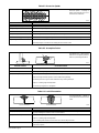
Auto Arc 175
230 Volt Wire Welder For GMAW And FCAW Welding
Rated Welding Out-
put
Maximum Open-
Circuit Voltage
DC
Amperes Input at
Rated Load Output
230 V, 60 Hz,
Single-Phase
KVA KW Weight
Overall
Dimensions
150 A @ 22 Volts DC,
40% Duty Cycle
32 26 (1.4)*
5.9
(0.33)*
4.9
(0.16)*
Net: 160 lb
(72.6 kg)
Ship: 180 lb
(81.6 kg)
Length: 34-1/2 in
(876 mm)
Width: 18-1/2 in
(470 mm)
Height: 22-1/4 in
(565 mm)
Wire Diameter Range Wire Feed Speed Range
.023 – .035 in (0.58 – 0.89 mm) 0 – 500 ipm (0 – 19.1 m/min)
* While idling


OM-170 823 Page 1
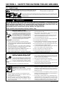
SECTION 1 – SAFETY PRECAUTIONS FOR ARC WELDING
safety_som1 4/95OM-170 823 - 7/96
1-1. Symbol Usage
Means Warning! Watch Out! There are possible hazards with this
procedure! The possible hazards are shown in the adjoining symbols.
This group of symbols means Warning! Watch Out! possible ELECTRIC SHOCK, MOVING PARTS,
and HOT PARTS hazards. Consult symbols and related instructions below for necessary actions to
avoid the hazards.
Y Marks a special safety message.
. Means NOTE; not safety related.
1-2. Arc Welding Hazards
WARNING
The symbols shown below are used throughout this manual to call attention to and identify possible
hazards. When you see the symbol, watch out, and follow the related instructions to avoid the hazard. The
safety information given below is only a summary of the more complete safety information found in the
Safety Standards listed in Section 1-4. Read and follow all Safety Standards.
Only qualified persons should install, operate, maintain, and repair this unit.
During operation, keep everybody, especially children, away.
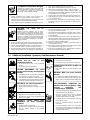
ELECTRIC SHOCK can kill.
Touching live electrical parts can cause fatal shocks
or severe burns. The electrode and work circuit is
electrically live whenever the output is on. The input
power circuit and machine internal circuits are also
live when power is on. In semiautomatic or
automatic wire welding, the wire, wire reel, drive roll
housing, and all metal parts touching the welding
wire are electrically live. Incorrectly installed or
improperly grounded equipment is a hazard.
1. Do not touch live electrical parts.
2. Wear dry, hole-free insulating gloves and body protection.
3. Insulate yourself from work and ground using dry insulating mats
or covers big enough to prevent any physical contact with the
work or ground.
4. Disconnect input power or stop engine before installing or
servicing this equipment. Lockout/tagout input power according
to OSHA 29 CFR 1910.147 (see Safety Standards).
5. Properly install and ground this equipment according to its
Owner’s Manual and national, state, and local codes.
6. Always verify the supply ground – check and be sure that input
power cord ground wire is properly connected to ground terminal
in disconnect box or that cord plug is connected to a properly
grounded receptacle outlet.
7. When making input connections, attach proper grounding
conductor first – double-check connections.
8. Frequently inspect input power cord for damage or bare wiring –
replace cord immediately if damaged – bare wiring can kill.
9. Turn off all equipment when not in use.
10. Do not use worn, damaged, undersized, or poorly spliced cables.
11. Do not drape cables over your body.
12. If earth grounding of the workpiece is required, ground it directly
with a separate cable – do not use work clamp or work cable.
13. Do not touch electrode if you are in contact with the work, ground,
or another electrode from a different machine.
14. Use only well-maintained equipment. Repair or replace damaged
parts at once. Maintain unit according to manual.
15. Wear a safety harness if working above floor level.
16. Keep all panels and covers securely in place.
17. Clamp work cable with good metal-to-metal contact to workpiece
or worktable as near the weld as practical.
ARC RAYS can burn eyes and skin;
NOISE can damage hearing; FLYING
SLAG OR SPARKS can injure eyes.
Arc rays from the welding process produce intense
visible and invisible (ultraviolet and infrared) rays
that can burn eyes and skin. Noise from some
processes can damage hearing. Chipping, grinding,
and welds cooling throw off pieces of metal or slag.
NOISE
1. Use approved ear plugs or ear muffs if noise level is high.
ARC RAYS
2. Wear a welding helmet fitted with a proper shade of filter to protect
your face and eyes when welding or watching (see ANSI Z49.1
and Z87.1 listed in Safety Standards).
3. Wear approved safety glasses with side shields.
4. Use protective screens or barriers to protect others from flash
and glare; warn others not to watch the arc.
5. Wear protective clothing made from durable, flame-resistant
material (wool and leather) and foot protection.
FUMES AND GASES can be
hazardous to your health.
Welding produces fumes and gases. Breathing
these fumes and gases can be hazardous to your
health.
1. Keep your head out of the fumes. Do not breathe the fumes.
2. If inside, ventilate the area and/or use exhaust at the arc to
remove welding fumes and gases.
3. If ventilation is poor, use an approved air-supplied respirator.
4. Read the Material Safety Data Sheets (MSDSs) and the
manufacturer’s instruction for metals, consumables, coatings,
cleaners, and degreasers.
5. Work in a confined space only if it is well ventilated, or while
wearing an air-supplied respirator. Always have a trained
watchperson nearby. Welding fumes and gases can displace air
and lower the oxygen level causing injury or death. Be sure the
breathing air is safe.
6. Do not weld in locations near degreasing, cleaning, or spraying
operations. The heat and rays of the arc can react with vapors to
form highly toxic and irritating gases.
7. Do not weld on coated metals, such as galvanized, lead, or
cadmium plated steel, unless the coating is removed from the
weld area, the area is well ventilated, and if necessary, while
wearing an air-supplied respirator. The coatings and any metals
containing these elements can give off toxic fumes if welded.

OM-170 823 Page 2
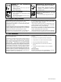
CYLINDERS can explode if damaged.
Shielding gas cylinders contain gas under high
pressure. If damaged, a cylinder can explode. Since
gas cylinders are normally part of the welding
process, be sure to treat them carefully.
1. Protect compressed gas cylinders from excessive heat,
mechanical shocks, slag, open flames, sparks, and arcs.
2. Install cylinders in an upright position by securing to a stationary
support or cylinder rack to prevent falling or tipping.
3. Keep cylinders away from any welding or other electrical circuits.
4. Never drape a welding torch over a gas cylinder.
5. Never allow a welding electrode to touch any cylinder.
6. Never weld on a pressurized cylinder – explosion will result.
7. Use only correct shielding gas cylinders, regulators, hoses, and
fittings designed for the specific application; maintain them and
associated parts in good condition.
8. Turn face away from valve outlet when opening cylinder valve.
9. Keep protective cap in place over valve except when cylinder is in
use or connected for use.
10. Read and follow instructions on compressed gas cylinders,
associated equipment, and CGA publication P-1 listed in Safety
Standards.
WELDING can cause fire or
explosion.
Welding on closed containers, such as tanks,
drums, or pipes, can cause them to blow up. Sparks
can fly off from the welding arc. The flying sparks,
hot workpiece, and hot equipment can cause fires
and burns. Accidental contact of electrode to metal
objects can cause sparks, explosion, overheating,
or fire. Check and be sure the area is safe before
doing any welding.
1. Protect yourself and others from flying sparks and hot metal.
2. Do not weld where flying sparks can strike flammable material.
3. Remove all flammables within 35 ft (10.7 m) of the welding arc. If
this is not possible, tightly cover them with approved covers.
4. Be alert that welding sparks and hot materials from welding can
easily go through small cracks and openings to adjacent areas.
5. Watch for fire, and keep a fire extinguisher nearby.
6. Be aware that welding on a ceiling, floor, bulkhead, or partition
can cause fire on the hidden side.
7. Do not weld on closed containers such as tanks, drums, or pipes,
unless they are properly prepared according to AWS F4.1 (see
Safety Standards).
8. Connect work cable to the work as close to the welding area as
practical to prevent welding current from traveling long, possibly
unknown paths and causing electric shock and fire hazards.
9. Do not use welder to thaw frozen pipes.
10. Remove stick electrode from holder or cut off welding wire at
contact tip when not in use.
11. Wear oil-free protective garments such as leather gloves, heavy
shirt, cuffless trousers, high shoes, and a cap.
12. Remove any combustibles, such as a butane lighter or matches,
from your person before doing any welding.
1-3. Additional Installation, Operation, And Maintenance Hazards
FIRE OR EXPLOSION can result from
placing unit on, over, or near
combustible surfaces.
1. Do not locate unit on, over, or near combustible
surfaces.
2. Do not install unit near flammables.
FALLING EQUIPMENT can cause
serious personal injury and equipment
damage.
1. Use lifting eye to lift unit only, NOT running gear,
gas cylinders, or any other accessories.
2. Use equipment of adequate capacity to lift unit.
3. If using lift forks to move unit, be sure forks are long
enough to extend beyond opposite side of unit.
HOT PARTS can cause severe burns.
1. Do not touch hot parts bare handed.
2. Allow cooling period before working on gun or
torch.
MOVING PARTS can cause injury.
1. Keep away from moving parts such as fans.
2. Keep all doors, panels, covers, and guards closed
and securely in place.
MAGNETIC FIELDS FROM HIGH
CURRENTS can affect pacemaker
operation.
1. Pacemaker wearers keep away.
2. Wearers should consult their doctor before going
near arc welding, gouging, or spot welding
operations.
MOVING PARTS can cause injury.
1. Keep away from moving parts.
2. Keep away from pinch points such as drive rolls.
FLYING PIECES OF METAL or DIRT can
injure eyes.
1. Wear safety glasses with side shields or face
shield.
WELDING WIRE can cause puncture
wounds.
1. Do not press gun trigger until instructed to do so.
2. Do not point gun toward any part of the body, other
people, or any metal when threading welding wire.
HIGH-FREQUENCY RADIATION can
interfere with radio navigation, safety
services, computers, and
communications equipment.
1. Have only qualified persons familiar with electronic
equipment perform this installation.
2. The user is responsible for having a qualified
electrician promptly correct any interference
problem resulting from the installation.
3. If notified by the FCC about interference, stop using
the equipment at once.
4. Have the installation regularly checked and
maintained.
5. Keep high-frequency source doors and panels
tightly shut, keep spark gaps at correct setting, and
use grounding and shielding to minimize the
possibility of interference.

OM-170 823 Page 3
OVERUSE can cause OVERHEATED
EQUIPMENT.
1. Allow cooling period.
2. Reduce current or reduce duty cycle before
starting to weld again.
3. Follow rated duty cycle.
STATIC ELECTRICITY can damage
parts on circuit boards.
1. Put on grounded wrist strap BEFORE handling
boards or parts.
2. Use proper static-proof bags and boxes to store,
move, or ship PC boards.
SIGNIFICANT DC VOLTAGE exists after
removal of input power on inverters.
1. Turn Off inverter, disconnect input power, and
discharge input capacitors according to
instructions in Maintenance Section before
touching any parts.
BUILDUP OF SHIELDING GAS can harm
health or kill.
1. Shut off shielding gas supply when not in use.
1-4. Principal Safety Standards
Safety in Welding and Cutting, ANSI Standard Z49.1, from American
Welding Society, 550 N.W. LeJeune Rd, Miami FL 33126
Safety and Health Standards, OSHA 29 CFR 1910, from
Superintendent of Documents, U.S. Government Printing Office,
Washington, D.C. 20402.
Recommended Safe Practices for the Preparation for Welding and
Cutting of Containers That Have Held Hazardous Substances,
American Welding Society Standard AWS F4.1, from American
Welding Society, 550 N.W. LeJeune Rd, Miami, FL 33126
National Electrical Code, NFPA Standard 70, from National Fire
Protection Association, Batterymarch Park, Quincy, MA 02269.
Safe Handling of Compressed Gases in Cylinders, CGA Pamphlet
P-1, from Compressed Gas Association, 1235 Jefferson Davis
Highway, Suite 501, Arlington, VA 22202.
Code for Safety in Welding and Cutting, CSA Standard W117.2, from
Canadian Standards Association, Standards Sales, 178 Rexdale
Boulevard, Rexdale, Ontario, Canada M9W 1R3.
Safe Practices For Occupation And Educational Eye And Face
Protection, ANSI Standard Z87.1, from American National Standards
Institute, 1430 Broadway, New York, NY 10018.
Cutting And Welding Processes, NFPA Standard 51B, from National
Fire Protection Association, Batterymarch Park, Quincy, MA 02269.
1-5. EMF Information
Considerations About Welding And The Effects Of Low Frequency
Electric And Magnetic Fields
The following is a quotation from the General Conclusions Section of
the U.S. Congress, Office of Technology Assessment, Biological
Effects of Power Frequency Electric & Magnetic Fields – Background
Paper, OTA-BP-E-53 (Washington, DC: U.S. Government Printing
Office, May 1989): “. . . there is now a very large volume of scientific
findings based on experiments at the cellular level and from studies
with animals and people which clearly establish that low frequency
magnetic fields can interact with, and produce changes in, biological
systems. While most of this work is of very high quality, the results are
complex. Current scientific understanding does not yet allow us to
interpret the evidence in a single coherent framework. Even more
frustrating, it does not yet allow us to draw definite conclusions about
questions of possible risk or to offer clear science-based advice on
strategies to minimize or avoid potential risks.”
To reduce magnetic fields in the workplace, use the following
procedures:
1. Keep cables close together by twisting or taping them.
2. Arrange cables to one side and away from the operator.
3. Do not coil or drape cables around the body.
4. Keep welding power source and cables as far away as
practical.
5. Connect work clamp to workpiece as close to the weld as
possible.
About Pacemakers:
The above procedures are also recommended for pacemaker
wearers. Consult your doctor for complete information.

OM-170 823 Page 4
SECTION 2 – INSTALLATION
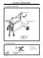
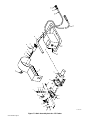
2-1. Installing The Running Gear
ST-801 364
See Parts List for descriptions.
Tools Needed:
Remove paint from axle grooves
before installing retaining rings.
Crimp S-hook and
snap to chain.
3/8, 9/16 in
2-2. Installing Work Clamp
1 Insulator
2 Bolt
3 Smaller Hole
4 Work Clamp Tabs
Bend tabs around work cable.
5 Work Cable From Unit
6 Nut
Ref. ST-025 190-D
1
2
3
4
5
6
Tools Needed:
3/8, 7/16 in

OM-170 823 Page 5
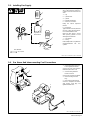
2-3. Installing Gas Supply
Chain gas cylinder to running gear,
wall, or other stationary support so
cylinder cannot fall and break off
valve.
1 Cap
2 Cylinder Valve
3 Cylinder
4 Regulator/Flowmeter
5 Gas Hose Connection
Fitting has 5/8-18 right-hand
threads.
6 Flow Adjust
Typical flow rate is 20 cfh (cubic feet
per hour). Check wire manufactur-
er’s recommended flow rate.
Make sure flow adjust is closed
when opening cylinder to avoid
damage to the flowmeter.
7CO
2
Adapter
8 O-Ring
Install adapter with O-ring between
regulator/flowmeter and CO
2
cylinder.
Tools Needed:
7 8
3
1
2
1
2
3
OR
5
4
6
ssb3.1* 5/94 – ST-158 697-A / Ref. ST-149 827-B
Argon Gas Or
Mixed Gases
CO
2
Gas
5/8, 1-1/8 in
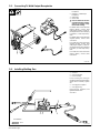
2-4. Gas Hoses And Interconnecting Cord Connections
Ref. ST-800 365 / Ref. ST-801 366
1 Gas In Fitting And Gas Hose
From Regulator/Flowmeter
Connect gas hose from regulator/
flowmeter (see Section 2-3).
2 Gas Out Fitting And Wire
Feeder Gas Hose
Connect gas hose from wire feeder.
3 Interconnecting Cord And
Plug
4 Interconnecting Receptacle
Connect to receptacle as follows:
align keyway, insert plug, and
tighten threaded collar.
2
1
3
4
2

OM-170 823 Page 6
2-5. Connecting To Weld Output Receptacles
ST-801 366
1 Positive (+) Weld Output
Receptacle
2 Negative (–) Weld Output
Receptacle
3 Weld Cable
4 Work Cable
Y Be sure cables are secure in
receptacles before welding,
and do not change recep-
tacles while welding.
For GMAW direct current electrode
positive (DCEP), connect weld
cable plug to positive (+) weld out-
put receptacle and work cable plug
to negative (–) weld output recep-
tacle.
For GMAW direct current electrode
negative (DCEN), reverse cable
connections.
For FCAW direct current electrode
negative (DCEN), connect weld
cable plug to negative (–) weld out-
put receptacle and work cable plug
to positive (+) weld output recep-
tacle.
For FCAW direct current electrode
positive (DCEP), reverse cable
connections.
3
4
1
2
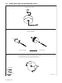
2-6. Installing Welding Gun
1 Gun End
2 Gun Securing Nut
3 Drive Assembly
Loosen securing nut. Insert gun
end through opening until it bottoms
against drive assembly. Tighten
nut.
4 Gun Trigger Receptacle
5 Gun Trigger Plug
Insert plug into receptacle, and
tighten threaded collar.
Close door.
Tools Needed:
ST-800 849-A
1/2 in
1
2345

OM-170 823 Page 7
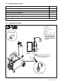
2-7. Electrical Service Guide
Input Voltage
230
Input Amperes At Rated Output
26
Max Recommended Standard Fuse Or Circuit Breaker Rating In Amperes
40
Min Input Conductor Size In AWG/Kcmil
12
Max Recommended Input Conductor Length In Feet (Meters)
80 (24)
Min Grounding Conductor Size In AWG/Kcmil
12
Reference: 1993 National Electrical Code (NEC) S-0092-J
2-8. Selecting A Location
ST-801 367
Have only qualified persons make
this installation.
1 Rating Label
Supply correct input power.
2 Plug
3 Receptacle
Obtain and install correct
receptacle.
Y Special installation may be
required where gasoline or
volatile liquids are present –
see NEC Article 511 or CEC
Section 20.
18 in (457 mm) of
space for airflow
1
L1L2
GND/PE
230 VAC, 1
Size and ratings must comply with
applicable codes. Install conductors
in conduit or equivalent into a deener-
gized line disconnect device.
GND/PE
GND/PE
Connect First
L2
L1
2
3

OM-170 823 Page 8
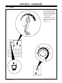
2-9. Installing Wire Spool And Adjusting Hub Tension
ST-800316 / S-0499
Standard Spool Installation
Tools Needed:
Remove and retain
Install 1 lb spool
1 lb Spool Installation
When a slight force is needed to turn spool, tension is set. If tension
is to tight, circuit breaker CB1 can open (see Section 4-3)
9/16 in

OM-170 823 Page 9
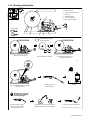
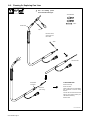
2-10. Threading Welding Wire
Ref. ST-800 851-A / Ref. ST-170 725 / S-0627-A
1 Wire Spool
2 Inlet Wire Guide
3 Pressure Adjustment Knob
4 Drive Roll
5 Outlet Wire Guide
6 Gun Conduit Cable
Lay gun cable out straight.
Tools Needed:
3
1245
6
6 in
(150 mm)
Hold wire tightly to keep
it from unraveling.
Tighten
WOOD
Welding wire is electrically
live when feeding welding
wire with gun trigger.
Turn On.
Cut off wire. Close and latch door.
Feed wire to check drive roll pressure.
Tighten knob enough to prevent slipping.
Remove gun nozzle
and contact tip.
Push wire thru guides into gun;
continue to hold wire.
Pull and hold wire, cut off end.
Open pressure assembly.
Close and tighten pressure assembly,
and let go of wire.
Press gun trigger until wire
comes out of gun. Reinstall
contact tip and nozzle.

OM-170 823 Page 10
SECTION 3 – OPERATION
Ref. ST-801 368 / Ref. ST-177 114 / ST-177 115
1 Wire Speed Control
Use control to select a wire feed
speed. As Voltage switch setting in-
creases, wire speed range also in-
creases. The numbers around the
control are not a wire feed speed
and are for reference only.
2 Voltage Switch
Use switch to select an arc voltage.
The higher the selected number,
the thicker the material that can be
welded.
3 Power Switch
3
1
ON
OFF
3-1. Controls
2

OM-170 823 Page 11
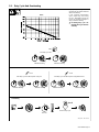
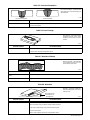
4 Minutes Welding 6 Minutes Resting
3-2. Duty Cycle And Overheating
Duty Cycle is percentage of 10 min-
utes that unit can weld at rated load
without overheating.
If unit overheats, thermostat(s)
opens, output stops, and cooling
fan runs. Wait fifteen minutes for
unit to cool. Reduce amperage or
duty cycle before welding.
Y Exceeding duty cycle can
damage unit or gun and void
warranty.
Overheating
0
15
A or V
OR
Reduce Duty Cycle
Minutes
duty1 4/95 – SB-173 353
40% Duty Cycle At 150 Amperes
6 Minutes Welding 4 Minutes Resting
UNIT
GUN
GUN
3 Minutes Welding 7 Minutes Resting
60% Duty Cycle At 160 Amperes Using CO
2
30% Duty Cycle At 160 Amperes Using Mixed Gases
Chart

OM-170 823 Page 12
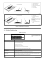
SECTION 4 – MAINTENANCE & TROUBLESHOOTING
4-1. Routine Maintenance
Y Disconnect power before maintaining.
3 Months
Repair Or
Replace
Cracked
Weld
Cable
Replace
Unreadable
Labels
Clean And
Tighten
Weld
Terminals
6 Months
Blow Out Or Vacuum
Inside,
During Heavy Service,
Clean Monthly
OR
4-2. Fuses F1 And F2
ST-801 369
Y Turn Off power. Remove
wrapper.
1 Fuse F1
2 Fuse F2
Pull fuse(s) from fuse holder, and
check and replace if needed. To re-
install, push fuse into fuse holder.
Reinstall wrapper.
Tools Needed:
3/8 in
2
1
4-3. Circuit Breaker CB1
ST-800 850-A
1 Circuit Breaker CB1
CB1 protects the wire feeder motor
from overload. If CB1 trips, wire
feeding stops. Check for jammed
wire or misaligned drive roll. Cor-
rect problem, reset breaker.
1

OM-170 823 Page 13
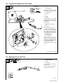
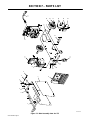
4-4. Cleaning Or Repairing Drive Assembly
Ref. ST-800 851-A / ST-155 578
Y Turn Off and unplug unit.
1 Wire Spool
2 Gun Contact Tip
Cut welding wire off at contact tip.
Retract wire onto spool and secure.
3 Pressure Roll Arm
4 Cotter Pin
5 Pin
6 Screw
7 Bearing
Remove bearing as shown. Install
new bearing and secure with screw.
Reinstall arm onto pin and secure
with cotter pin.
8 Setscrew
9 Smooth Groove For Hard
Wire
10 Drive Roll
Remove drive roll as shown.
Use a wire brush to clean drive roll.
Push drive roll onto shaft with de-
sired groove in. Turn drive roll so
one setscrew faces flat side of
shaft, and tighten both setscrews.
11 Knurled Groove For
Flux-Cored Wire
12 Wire Inlet Guide
Remove guide by pressing on
barbed area or cutting off one end
near housing and pulling it out of
hole. Push new guide into hole from
rear until it snaps in place.
Thread welding wire (see Section
2-10).
4
5
6
7
8
9
10
11
12
8
3
1
2
Tools Needed:
5/64 in
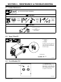
4-5. Replacing Gun Contact Tip
ST-149 632-C
Y Turn Off power before re-
placing contact tip.
1 Nozzle
2 Contact Tip
Cut off welding wire at contact tip.
Remove nozzle.
Remove contact tip and install new
contact tip. Reinstall nozzle.
Tools Needed:
1
2

OM-170 823 Page 14
4-6. Cleaning Or Replacing Gun Liner
Ref. ST-155 509
Tools Needed:
3/8 in
To Reassemble Gun:
Install contact tip.
Insert new liner.
Install collet onto liner and tighten
into gun/feeder connector using
wrench.
Cut liner off near collet so that liner
end is as close to drive rolls as pos-
sible without touching.
Install nozzle.
Y Turn off welding power
source and disconnect gun.
Remove nozzle,
contact tip, and
liner collet.
3/8 in
3/8 in
Head Tube
Gun/feeder
Connector
Blow out
gun casing.
Remove liner.

OM-170 823 Page 15
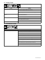
4-7. Welding Trouble
Trouble Remedy
No weld output; wire does not feed; fan does not run. Secure power cord plug in receptacle (see Section 2-8).
Replace line disconnect fuse or reset circuit breaker if open (see Section 2-8).
Secure gun trigger plug in receptacle or repair leads, or replace trigger switch (see Section
2-6).
No weld output; wire does not feed; fan motor contin-
ues to run.
Thermostat TP1 open (overheating). Allow fan to run; the thermostat will close when the
unit has cooled (see Section 3-2).
Check circuit breaker CB1, and reset if necessary (see Section 4-3).
No weld output; wire feeds. Connect work clamp to get good metal to metal contact.
Check for proper weld cable connections.
Replace contact tip (see Section 4-5).
Low weld output. Connect unit to proper input voltage or check for low line voltage (see Section 2-8).
4-8. Wire Drive/Gun Trouble
Trouble Remedy
Electrode wire feeding stops during welding. Straighten gun cable and/or replace damaged parts.
Adjust drive roll pressure (see Section 2-10).
Change to proper groove (see Section 4-4).
Readjust hub tension (see Section 2-9).
Replace contact tip if blocked (see Section 4-5).
Clean or replace wire inlet guide or liner if dirty or plugged (see Section 4-6).
Replace drive roll or pressure bearing if worn or slipping (see Section 4-4).
Secure gun trigger plug in receptacle or repair leads, or replace trigger switch (see Section
2-6).
Check circuit breaker CB1, and reset if necessary (see Section 4-3).
Check and clear any restrictions at drive assembly and liner (see Sections 4-4 and 4-6).
Have nearest Factory Authorized Service Agent check drive motor.

OM-170 823 Page 16
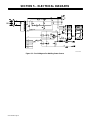
SECTION 5 – ELECTRICAL DIAGRAMS
SB-170 520-A
Figure 5-1. Circuit Diagram For Welding Power Source

OM-170 823 Page 17
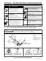
SECTION 6 – WELDING METHODS & TROUBLESHOOTING
mod4.1 9/92
WARNING
ELECTRIC SHOCK can kill.
• Always wear dry insulating gloves.
• Insulate yourself from work and ground.
• Do not touch live electrical parts.
• Keep all panels and covers securely in place.
FUMES AND GASES can be hazardous
to your health.
• Keep your head out of the fumes.
• Ventilate area, or use breathing device.
• Read Material Safety Data Sheets (MSDSs) and
manufacturer’s instructions for material used.
WELDING can cause fire or explosion.
• Do not weld near flammable material.
• Watch for fire; keep extinguisher nearby.
• Do not locate unit over combustible surfaces.
• Do not weld on closed containers.
• Allow work and equipment to cool before handling.
ARC RAYS can burn eyes and skin;
NOISE can damage hearing.
• Wear welding helmet with correct shade of filter.
• Wear correct eye, ear, and body protection.
MOVING PARTS can cause injury.
• Keep away from pinch points such as drive rolls.
• Keep all doors, panels, covers, and guards closed
and securely in place.
MAGNETIC FIELDS FROM HIGH CUR-
RENTS can affect pacemaker operation.
• Pacemaker wearers keep away.
• Wearers should consult their doctor before going
near arc welding, gouging, or spot welding opera-
tions.
WELDING CURRENT can damage elec-
tronic parts in vehicles.
• Disconnect both battery cables before welding on a
vehicle.
• Place work clamp as close to the weld as possible.
See Safety Precautions at beginning of manual for ba-
sic welding safety information.
swarn6.2 10/91
6-1. Flux Cored Arc Welding (FCAW) And Gas Metal Arc Welding (GMAW)
Welding wire is not energized until gun trigger is pressed; therefore, welding wire
should extend not more than 1/2 in (13 mm) beyond edge of nozzle and tip of wire
placed on seam before lowering helmet and pressing trigger.
NOTE
1 Hold Gun And Control Gun
Trigger
2 Workpiece
3 Work Clamp
4 Electrode Extension (Stickout)
1/4 To 1/2 in (6 To 13 mm)
5 Cradle Gun And Rest Hand
On Workpiece
S-0421-A
2
3
5
90° 90°
0°-15°
45°
45°
GROOVE WELDS FILLET WELDS
End View Of Work Angle Side View Of Gun Angle End View Of Work Angle Side View Of Gun Angle
1
0°-15°
4
Figure 6-1. Holding And Positioning Welding Gun

OM-170 823 Page 18
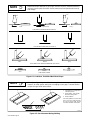
Weld bead shape depends on gun angle, direction of travel, electrode extension
(stickout), travel speed, thickness of base metal, wire feed speed (weld current),
and voltage.
NOTE
S-0634
Short Normal Long
Short Normal Long
10°
10°
GUN ANGLES AND WELD BEAD PROFILES
ELECTRODE EXTENSIONS (STICKOUT)
FILLET WELD ELECTRODE EXTENSIONS (STICKOUT)
Push Perpendicular Drag
GUN TRAVEL SPEED
Slow
Normal Fast
Figure 6-2. Conditions That Affect Weld Bead Shape
Normally, a single stringer bead is satisfactory for most narrow groove weld joints;
however, for wide groove weld joints or bridging across gaps, a weave bead or
multiple stringer beads works better.
NOTE
1 Stringer Bead – Steady Move-
ment Along Seam
2 Weave Bead – Side To Side
Movement Along Seam
3 Weave Patterns
Use weave patterns to cover a wide
area in one pass of the electrode.
Do not let weave width exceed
2-1/2 times diameter of electrode.
S-0054-A
1
2
3
Figure 6-3. Gun Movement During Welding
Page is loading ...
Page is loading ...
Page is loading ...
Page is loading ...
Page is loading ...
Page is loading ...
Page is loading ...
Page is loading ...
Page is loading ...
Page is loading ...
Page is loading ...
Page is loading ...
-
 1
1
-
 2
2
-
 3
3
-
 4
4
-
 5
5
-
 6
6
-
 7
7
-
 8
8
-
 9
9
-
 10
10
-
 11
11
-
 12
12
-
 13
13
-
 14
14
-
 15
15
-
 16
16
-
 17
17
-
 18
18
-
 19
19
-
 20
20
-
 21
21
-
 22
22
-
 23
23
-
 24
24
-
 25
25
-
 26
26
-
 27
27
-
 28
28
-
 29
29
-
 30
30
-
 31
31
-
 32
32


Miller AUTO ARC 175 Owner's manual
- Category
- Welding System
- Type
- Owner's manual
- This manual is also suitable for
Ask a question and I''ll find the answer in the document
Finding information in a document is now easier with AI
Related papers
-
Miller KF975790 Owner's manual
-
-
-
-
Miller GA-16C1 Owner's manual
-
-
-
-
-
Other documents
-
Hobart Welding Products OLYMPIC XRA A User manual
-
American Range ARR244SBP American Range Warranty
-
Python 248-8XX User manual
-
 MK Products 091-0593 User manual
-
Hobart Handler 190 Technical Manual
-
-
ESAB ST-21 Mig Welding Torch Troubleshooting instruction
-
ETS 823/847 User manual
-
-
GYS SPEEDLINER Owner's manual
