Page is loading ...

www.HobartWelders.com
TM-260 273B 2013−02
Eff. w/Serial No. MC420249Y
Processes
Arc Welding Power Source And
Wire Feeder
Description
MIG (GMAW) Welding
Flux Cored (FCAW) Welding
File: MIG (GMAW)
Handler 190 And
H100S4-10 Gun
R

TABLE OF CONTENTS
SECTION 1 − SAFETY PRECAUTIONS FOR SERVICING 1........................................
1-1. Symbol Usage 1.................................................................
1-2. Servicing Hazards 1..............................................................
1-3. California Proposition 65 Warnings 2.................................................
1-4. EMF Information 2................................................................
SECTION 2 − SPECIFICATIONS 3..............................................................
2-1. Serial Number And Rating Label Location 3...........................................
2-2. Unit Specifications 3..............................................................
2-3. Duty Cycle And Overheating 3......................................................
2-4. Volt-Ampere Curves 4.............................................................
SECTION 3 − INSTALLATION 4................................................................
3-1. Installing Nozzle, Contact Tip, And Adapter 4.........................................
3-2. Installing Welding Gun 5...........................................................
3-3. Installing Work Clamp 6...........................................................
3-4. Process/Polarity Table 7...........................................................
3-5. Changing Polarity 7...............................................................
3-6. Installing Gas Supply 8............................................................
3-7. Serial Number And Rating Label Location 9...........................................
3-8. Selecting A Location 9.............................................................
3-9. Installing Wire Spool And Adjusting Hub Tension 10.....................................
3-10. Electrical Service Guide 11..........................................................
3-11. Connecting Input Power 12..........................................................
3-12. Connecting Optional Spool Gun 14...................................................
3-13. Threading Welding Wire 15..........................................................
SECTION 4 − OPERATION 16..................................................................
4-1. Controls 16.......................................................................
4-2. Weld Parameter Chart For 230 VAC Model 17..........................................
SECTION 5 − THEORY OF OPERATION 18.......................................................
SECTION 6 − TROUBLESHOOTING 20..........................................................
6-1. Troubleshooting Table 20...........................................................
6-2. Troubleshooting Circuit Diagram For Welding Power Source 22...........................
6-3. Control Board PC1 Testing Information 24.............................................
6-4. Control Board PC1 Test Point Values 25...............................................
SECTION 7 − MAINTENANCE 26................................................................
7-1. Routine Maintenance 26............................................................
7-2. Overload Protection 26.............................................................
7-3. Drive Motor Protection 26...........................................................
7-4. Changing Drive Roll Or Wire Inlet Guide 27............................................
7-5. Changing Nozzle, Contact Tip, Adapter And Liner, And Cleaning Gun Casing 28.............
7-6. Replacing Switch And/Or Head Tube 29...............................................
SECTION 8 − ELECTRICAL DIAGRAMS 31......................................................
SECTION 9 − PARTS LIST 40...................................................................
9-4. Optional Drive Rolls 45.............................................................
9-5. Options 45.......................................................................
9-6. Consumables 45..................................................................
Hobart is registered to
the ISO 9001 Quality
System Standard.

TM-260 273 Page 1Handler 190
SECTION 1 − SAFETY PRECAUTIONS FOR SERVICING
Protect yourself and others from injury — read, follow, and save these important safety precautions and operating instructions.
1-1. Symbol Usage
OM-260 273-A - 2012−10, safety_stm 2011−10
DANGER! − Indicates a hazardous situation which, if
not avoided, will result in death or serious injury. The
possible hazards are shown in the adjoining symbols
or explained in the text.
Indicates a hazardous situation which, if not avoided,
could result in death or serious injury. The possible
hazards are shown in the adjoining symbols or ex-
plained in the text.
NOTICE − Indicates statements not related to personal injury.
. Indicates special instructions.
This group of symbols means Warning! Watch Out! ELECTRIC
SHOCK, MOVING PARTS, and HOT PARTS hazards. Consult sym-
bols and related instructions below for necessary actions to avoid the
hazards.
1-2. Servicing Hazards
The symbols shown below are used throughout this manual
to call attention to and identify possible hazards. When you
see the symbol, watch out, and follow the related instructions
to avoid the hazard.
Only qualified persons should test, maintain, and repair this
unit.
During servicing, keep everybody, especially children, away.
ELECTRIC SHOCK can kill.
D Do not touch live electrical parts.
D Turn Off welding power source and wire feeder
and disconnect and lockout input power using
line disconnect switch, circuit breakers, or by removing plug from re-
ceptacle, or stop engine before servicing unless the procedure spe-
cifically requires an energized unit.
D Insulate yourself from ground by standing or working on dry insulat-
ing mats big enough to prevent contact with the ground.
D Do not leave live unit unattended.
D If this procedure requires an energized unit, have only personnel
familiar with and following standard safety practices do the job.
D When testing a live unit, use the one-hand method. Do not put both
hands inside unit. Keep one hand free.
D Disconnect input power conductors from deenergized supply line
BEFORE moving a welding power source.
SIGNIFICANT DC VOLTAGE exists in inverter weld-
ing power sources AFTER removal of input power.
D Turn Off inverter, disconnect input power, and discharge input
capacitors according to instructions in Troubleshooting Section be-
fore touching any parts.
STATIC (ESD) can damage PC boards.
D Put on grounded wrist strap BEFORE handling
boards or parts.
D Use proper static-proof bags and boxes to
store, move, or ship PC boards.
FIRE OR EXPLOSION hazard.
D Do not place unit on, over, or near combustible
surfaces.
D Do not service unit near flammables.
FLYING METAL or DIRT can injure eyes.
D Wear safety glasses with side shields or face
shield during servicing.
D Be careful not to short metal tools, parts, or
wires together during testing and servicing.
HOT PARTS can burn.
D Do not touch hot parts bare handed.
D Allow cooling period before working on
equipment.
D To handle hot parts, use proper tools and/or
wear heavy, insulated welding gloves and
clothing to prevent burns.
EXPLODING PARTS can injure.
D Failed parts can explode or cause other parts to
explode when power is applied to inverters.
D Always wear a face shield and long sleeves
when servicing inverters.
SHOCK HAZARD from testing.
D Turn Off welding power source and wire feeder
or stop engine before making or changing me-
ter lead connections.
D Use at least one meter lead that has a self-
retaining spring clip such as an alligator clip.
D Read instructions for test equipment.
FALLING EQUIPMENT can injure.
D Use lifting eye to lift unit only, NOT running
gear, gas cylinders, or any other accessories.
D Use equipment of adequate capacity to lift and
support unit.
D If using lift forks to move unit, be sure forks are long enough to
extend beyond opposite side of unit.
D Follow the guidelines in the Applications Manual for the Revised
NIOSH Lifting Equation (Publication No. 94−110) when manu-
ally lifting heavy parts or equipment.

TM-260 273 Page 2 Handler 190
MOVING PARTS can injure.
D Keep away from moving parts such as fans.
D Keep away from pinch points such as drive
rolls.
D Have only qualified persons remove doors,
panels, covers, or guards for maintenance and
troubleshooting as necessary.
D Keep hands, hair, loose clothing, and tools
away from moving parts.
D Reinstall doors, panels, covers, or guards
when maintenance is finished and before re-
connecting input power.
ELECTRIC AND MAGNETIC FIELDS (EMF)
can affect Implanted Medical Devices.
D Wearers of Pacemakers and other Implanted
Medical Devices should keep away from serv-
icing areas until consulting their doctor and the
device manufacturer.
OVERUSE can cause OVERHEATING.
D Allow cooling period; follow rated duty cycle.
D Reduce current or reduce duty cycle before
starting to weld again.
D Do not block or filter airflow to unit.
H.F. RADIATION can cause interference.
D High-frequency (H.F.) can interfere with radio
navigation, safety services, computers, and
communications equipment.
D Have only qualified persons familiar with
electronic equipment install, test, and service
H.F. producing units.
D The user is responsible for having a qualified electrician prompt-
ly correct any interference problem resulting from the installa-
tion.
D If notified by the FCC about interference, stop using the
equipment at once.
D Have the installation regularly checked and maintained.
D Keep high-frequency source doors and panels tightly shut, keep
spark gaps at correct setting, and use grounding and shielding to
minimize the possibility of interference.
READ INSTRUCTIONS.
D Use Testing Booklet (Part No. 150 853) when
servicing this unit.
D Consult the Owner’s Manual for welding safety
precautions.
D Use only genuine replacement parts from the manufacturer.
D Read and follow all labels and the Technical Manual carefully be-
fore installing, operating, or servicing unit. Read the safety in-
formation at the beginning of the manual and in each section.
1-3. California Proposition 65 Warnings
Welding or cutting equipment produces fumes or gases
which contain chemicals known to the State of California to
cause birth defects and, in some cases, cancer. (California
Health & Safety Code Section 25249.5 et seq.)
This product contains chemicals, including lead, known to
the state of California to cause cancer, birth defects, or other
reproductive harm. Wash hands after use.
1-4. EMF Information
Electric current flowing through any conductor causes localized electric
and magnetic fields (EMF). Welding current creates an EMF field
around the welding circuit and welding equipment. EMF fields may inter-
fere with some medical implants, e.g. pacemakers. Protective
measures for persons wearing medical implants have to be taken. For
example, restrict access for passers−by or conduct individual risk as-
sessment for welders. All welders should use the following procedures
in order to minimize exposure to EMF fields from the welding circuit:
1. Keep cables close together by twisting or taping them, or using a
cable cover.
2. Do not place your body between welding cables. Arrange cables
to one side and away from the operator.
3. Do not coil or drape cables around your body.
4. Keep head and trunk as far away from the equipment in the
welding circuit as possible.
5. Connect work clamp to workpiece as close to the weld as
possible.
6. Do not work next to, sit or lean on the welding power source.
7. Do not weld whilst carrying the welding power source or wire
feeder.
About Implanted Medical Devices:
Implanted Medical Device wearers should consult their doctor and the
device manufacturer before performing or going near arc welding, spot
welding, gouging, plasma arc cutting, or induction heating operations.
If cleared by your doctor, then following the above procedures is recom-
mended.

TM-260 273 Page 3Handler 190
SECTION 2 − SPECIFICATIONS
2-1. Serial Number And Rating Label Location
The serial number and rating information for this product is located on back. Use rating label to determine input power requirements and/or rated output.
For future reference, write serial number in space provided on back cover of this manual.
2-2. Unit Specifications
Rated Welding
Output
Amperage
Range
Maximum Open-
Circuit Voltage
DC
Amperes Input at
Rated Load Output
230 V, 60 Hz,
Single-Phase
KVA KW
Weight
W/ Gun
Overall
Dimensions
130 A @ 21.5 Volts
DC, 30% Duty Cycle
25 − 190
31 20.5 4.7 3.88
68 lb
(31 kg)
Length: 19-1/2 in.
(495 mm)
Width: 10-5/8 in.
(270 mm)
Height: 12-3/8 in.
(314 mm)
Wire Type
And Diameter
Solid/
Stainless
Flux Cored Aluminum
Wire Feed Speed Range
.023 − .035 in.
(0.6 − 0.9 mm)
.030 − .045 in.
(0.8 − 1.2 mm)
.030 − .035 in.
(0.8 − 0.9 mm)
50 − 740 IPM (1.3 − 18.8 m/min) At No Load
40 − 700 IPM (1.0 − 17.8 m/min) Feeding Wire
2-3. Duty Cycle And Overheating
Duty Cycle is percentage of 10
minutes that unit can weld at rated
load without overheating.
If unit overheats, thermostat(s)
opens, output stops, and cooling
fan runs. Wait fifteen minutes for
unit to cool. Reduce amperage or
duty cycle before welding.
NOTICE − Exceeding duty cycle
can damage unit or gun and void
warranty.
Overheating
0
15
A or V
OR
Reduce Duty Cycle
Minutes
duty1 4/95 − 248 832-A
30% duty cycle at 130 amps
3 Minutes Welding 7 Minutes Resting
Output Amperes
Duty Cycle %
10
20
40
60
80
100
200
10 20 30 40 50
60 70 80 100
130
175

TM-260 273 Page 4 Handler 190
2-4. Volt-Ampere Curves
The volt-ampere curves show the
minimum and maximum voltage
and amperage output capabilities of
the welding power source. Curves
of other settings fall between the
curves shown.
ssb1.1 10/91 − 248 833-A
0
5
10
15
20
25
30
0 10 20 30 40 50 60 70 80 90 100 110 120 130 140 150 160 170 180 190 200
Voltage
Amperage
1
2
3
4
5
6
7
SECTION 3 − INSTALLATION
3-1. Installing Nozzle, Contact Tip, And Adapter
Ref. 243 839-A
! Turn off welding power
source.
1 Nozzle
2 Contact Tip
3 Tip Adapter
. Wire size stamped on tip − check
and match wire size.
Tools Needed:
8 mm
Head
Tube
8 mm
1
3
2

TM-260 273 Page 5Handler 190
3-2. Installing Welding Gun
260 458-A
1 Drive Assembly
2 MIG Gun
3 Gun Securing Thumbscrew
4 Gun End
Loosen thumbscrew. Insert end
through opening until it bottoms
against drive assembly. Tighten
thumbscrew.
Welding gun must be inserted
completely to prevent leakage of
shielding gas.
5 Gun Trigger Plug
Insert plug into receptacle, and
tighten threaded collar.
6 Spool Gun/MIG Gun Switch
Place switch in MIG Gun position.
Close door.
Correct
Incorrect
. Be sure that gun end is tight against drive assembly.
4
Gun Fully Seated
4
Gun Not Seated
Exposed O-rings
will cause shielding
gas leakage.
Spool Gun
5
MIG Gun
6
1
3
2
4

TM-260 273 Page 6 Handler 190
3-3. Installing Work Clamp
258 550-A
1
2
3
4
5
6
. Connection hardware must be tightened with proper
tools. Do not just hand tighten hardware. A loose
electrical connection will cause poor weld performance
and excessive heating of the work clamp.
1 Work Clamp
2 Work Cable From Unit
3 Screw
4 Flat Washer
5 Lock Washer
6 Nut
Route work cable through hole in
clamp handle. Secure cable with
hardware as shown.
Tools Needed:
10 mm

TM-260 273 Page 7Handler 190
3-4. Process/Polarity Table
Process Polarity
Cable Connections
Cable To Gun Cable To Work
GMAW − Solid wire with shield-
ing gas
DCEP − Reverse polarity Connect to positive (+) out-
put terminal
Connect to negative (−) output
terminal
FCAW − Self-shielding wire −
no shielding gas
DCEN − Straight Polarity Connect to negative (−)
output terminal
Connect to positive (+) output
terminal
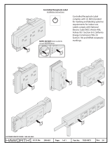
3-5. Changing Polarity
! Turn off welding power
source.
1 Lead Connections For Direct
Current Electrode Negative
(DCEN)
2 Lead Connections For Direct
Current Electrode Positive
(DCEP)
Always read and follow wire
manufacturer’s recommended
polarity, and see Section 3-4.
Close door.
260 459-A
1
2
CHANGING
POLARITY
DCEN
Electrode negative
for flux cored wire
DCEP
Electrode positive
for solid wire

TM-260 273 Page 8 Handler 190
3-6. Installing Gas Supply
Obtain gas cylinder and chain to
running gear, wall, or other
stationary support so cylinder
cannot fall and break off valve.
1 Cap
2 Cylinder Valve
Remove cap, stand to side of valve,
and open valve slightly. Gas flow
blows dust and dirt from valve.
Close valve.
3 Cylinder
4 Regulator/Flowmeter
Install so face is vertical.
5 Regulator/Flowmeter Gas
Hose Connection
6 Welding Power Source Gas
Hose Connection
Connect supplied gas hose
between regulator/flowmeter gas
hose connection, and fitting on rear
of welding power source.
7 Flow Adjust
Flow rate should be set when gas is
flowing through welding power
source and welding gun. Open
pressure assembly so that wire will
not feed. Press gun trigger to start
gas flow.
Typical flow rate is 20 cfh (cubic
feet per hour). Check wire
manufacturer’s recommended
flow rate.
After flow is set, close pressure
assembly.
260 460-A
. DO NOT use Argon/Mixed gas regulator/flowmeter
with CO
2
shielding gas. See Parts List for optional
CO
2
gas regulator/flowmeter.
Pressure Assembly
Open
Pressure Assembly
Closed
Argon Gas Or
Mixed Gas
1
2
3
4
5
7
6
Tools Needed:
5/8 or 11/16, 1-1/8 in.

TM-260 273 Page 9Handler 190
3-7. Serial Number And Rating Label Location
The serial number and rating information for this product is located on the back. Use rating label to determine input power requirements and/or rated
output. For future reference, write serial number in space provided on back cover of this manual.
1 Line Disconnect Device
Locate unit near correct input power
supply.
! Special installation may be
required where gasoline or
volatile liquids are present −
see NEC Article 511 or CEC
Section 20.
3-8. Selecting A Location
1
18 in
(460 mm)
18 in
(460 mm)
Location And Airflow
260 711-B / ST-139 445-E
! Do not move or operate unit
where it could tip.

TM-260 273 Page 10 Handler 190
3-9. Installing Wire Spool And Adjusting Hub Tension
When a slight force is needed
to turn spool, tension is set.
1/2 in.
Tools Needed:
803 012 / 803 013 -B / Ref. 802 971-C
Installing 8 in. (203 mm) Wire Spool
Installing 4 in. (102 mm) Wire Spool
When a slight force is needed
to turn spool, tension is set.
Retaining ring used
with 8 in. (203 mm)
spool only.
Adapter used with
8 in. (203 mm)
spool only.

TM-260 273 Page 11Handler 190
3-10. Electrical Service Guide
Elec Serv 2011−08
Failure to follow these electrical service guide recommendations could create an electric shock or fire hazard. These recommenda-
tions are for a dedicated circuit sized for the rated output and duty cycle of the welding power source.
In dedicated circuit installations, the National Electrical Code (NEC) allows the receptacle or conductor rating to be less than the rating
of the circuit protection device. All components of the circuit must be physically compatible. See NEC articles 210.21, 630.11, and
630.12.
60 Hz
Single
Phase
Input Voltage (V) 230
Input Amperes (A) At Rated Output 20.5
Max Recommended Standard Fuse Rating In Amperes
1
Time-Delay Fuses
2
25
Normal Operating Fuses
3
30
Min Input Conductor Size In AWG
4
14
Max Recommended Input Conductor Length In Feet (Meters)
67
(20)
Min Grounding Conductor Size In AWG
4
14
Reference: 2011 National Electrical Code (NEC) (including article 630)
1 If a circuit breaker is used in place of a fuse, choose a circuit breaker with time-current curves comparable to the recommended fuse.
2 “Time-Delay” fuses are UL class “RK5” . See UL 248.
3 “Normal Operating” (general purpose - no intentional delay) fuses are UL class “K5” (up to and including 60 amps), and UL class “H” ( 65 amps and
above).
4 Conductor data in this section specifies conductor size (excluding flexible cord or cable) between the panelboard and the equipment per NEC Table
310.15(B)(16). If a flexible cord or cable is used, minimum conductor size may increase. See NEC Table 400.5(A) for flexible cord and cable
requirements.

TM-260 273 Page 12 Handler 190
3-11. Connecting Input Power
input4 2012−05 − Ref. 803 766-C / 260 711-A
L1
L2
230 VAC, 1
7
9
Tools Needed:
2
1
L1
L2
1
=GND/PE Earth Ground
6
5
3
4
7

TM-260 273 Page 13Handler 190
input4 2012−05 − 803 766-C / 260 711-A
! Installation must meet all National and
Local Codes − have only qualified per-
sons make this installation.
! Disconnect and lockout/tagout input
power before connecting input con-
ductors from unit. Follow established
procedures regarding the installation
and removal of lockout/tagout
devices.
! Always connect green or green/yellow
conductor to supply grounding termi-
nal first, and never to a line terminal.
See rating label on unit and check input volt-
age available at site.
1 Input Power Cord
2 Disconnect Device (switch shown in the
OFF position)
3 Disconnect Device Grounding Terminal
4 Disconnect Device Line Terminals
5 Black And White Input Conductor (L1
And L2)
6 Green Or Green/Yellow Grounding
Conductor
Connect green or green/yellow grounding
conductor to disconnect device grounding
terminal first.
Connect input conductors L1 and L2 to dis-
connect device line terminals.
7 Over-Current Protection
Select type and size of over-current protec-
tion using Section 3-10 (fused disconnect
switch shown).
8 Receptacle (NEMA 6-50R)
Connect receptacle as shown.
Close and secure door on disconnect device.
Follow established lockout/tagout proced-
ures to put unit in service.
9 Plug (NEMA 6-50P)
Connect plug to receptacle.
3-11. Connecting 1-Phase Input Power (Continued)
Notes
Work like a Pro!
Pros weld and cut
safely. Read the
safety rules at
the beginning
of this manual.

TM-260 273 Page 14 Handler 190
3-12. Connecting Optional Spool Gun
260 573-A
1 Drive Assembly
2 Spool Gun
3 Gun Securing Thumbscrew
4 Gun End
Loosen thumbscrew. Insert end
through opening until it bottoms
against drive assembly. Tighten
thumbscrew.
Spool gun must be inserted
completely to prevent leakage of
shielding gas.
5 Gun Trigger Plug
Insert plug into receptacle, and
tighten threaded collar.
6 Spool Gun/MIG Gun Switch
Place switch in Spool Gun position.
7 Polarity Changeover Terminal
Block
To make proper polarity connection,
see welding power source Owner’s
Manual.
Close door.
8 Wire Feed Speed Control
Wire feed speed is controlled by
welding power source Wire Speed
control (see welding power source
Owner’s Manual or door chart for
appropriate setting).
9 Voltage Control
Arc voltage is controlled by welding
power source Voltage control (see
welding power source Owner’s
Manual or door chart for
appropriate setting).
10 Trigger
Press trigger to energize welding
power source contactor, start
shielding gas flow, and begin wire
feed.
CorrectIncorrect
. Be sure that gun end is tight against drive assembly.
4
Gun Fully Seated
4
Gun Not Seated
Exposed O-rings will cause
shielding gas leakage.
Spool Gun
MIG Gun
6
10
8
9
5
1
3
2
4
7

TM-260 273 Page 15Handler 190
3-13. Threading Welding Wire
1 Wire Spool
2 Welding Wire
3 Inlet Wire Guide
4 Pressure Adjustment Knob
5 Drive Roll
6 Gun Conduit Cable
Lay gun cable out straight.
Tools Needed:
Pull and hold wire; cut off end.
Remove gun nozzle
and contact tip.
Open pressure assembly. Make sure
feed roll is set to correct groove to
match wire size (see Section 7-4).
Push wire thru guides into gun;
continue to hold wire.
. Hold wire tightly to keep it
from unraveling.
260 587-A
WOOD
Feed wire to check drive roll pressure.
Tighten knob enough to prevent slipping.
Cut off wire. Close door.
Press gun trigger until wire comes
out of gun.
Turn power on. Be sure that Voltage range
switch is set to range 1, 2, 3, 4, 5, 6, or 7 to
feed wire. Rotate knob until it “clicks” into
detent. Wire will not feed if range switch is
set between ranges.
6 in
(150 mm)
Tighten
. Use pressure indicator
scale to set a desired
drive roll pressure.
Pressure
Indicator
Scale
Tighten
Be sure that wire is positioned
in proper feed roll groove.
Close and tighten pressure
assembly, and let go of wire.
Be sure that tip matches wire diameter.
Reinstall contact tip and nozzle.
4 in
(120 mm)
6
13
4
52

TM-260 273 Page 16 Handler 190
SECTION 4 − OPERATION
4-1. Controls
1 Wire Speed Control
Use control to select a wire feed speed. As
Voltage switch setting increases, wire
speed range also increases (see weld
setting label in welding power source or
Section 4-2, as applicable).
2 Power Switch
3 Voltage Switch
The higher the selected number, the
thicker the material that can be welded
(see weld setting label in welding power
source or Section 4-2, as applicable). Do
not switch under load.
. Switch must “click” into detent
position.
4 Gun Trigger Receptacle
5 Trigger Switch
When pressed, energized wire feeds and
shielding gas flows.
Ref. 248 840-A / Ref. 246 668-A
5
2
3
1
4

TM-260 273 Page 17Handler 190
4-2. Weld Parameter Chart For 230 VAC Model
248 827-B

Handler 190TM-260 273 Page 18
1 Supplementary Protector CB1
Protects unit from an over-current
condition by opening primary power
line.
2 Power Switch S1
Turns unit and fan motor FM on and
off.
3 Contactor CR3
Turns weld output on and off.
Provides shielding gas flow when
CR3 is energized.
4 Fan Motor FM And Control
Transformer
Controlled by power switch S1. Fan
cools internal components, and
transformer supplies 24 volts ac to
PC1 control circuit.
5 Range Switch S2
Allows selection of a primary
winding tap which provides a weld
output voltage level.
6 Gas Valve GS1
Provides shielding gas flow when
CR3 is energized.
7 Control Board PC1
Switches weld output on and off by
controlling CR3. Regulates motor
speed at a percentage set with Wire
Speed control R2. Provides
dynamic motor braking and starting
through the motor relay. Provides a
bleeder resistor for capacitor C1.
8 Thermostat TP1
If main transformer overheats, TP1
opens gun switch circuit stopping
all weld output.
9 Gun Trigger Receptacle RC7
Connects gun trigger circuit to
welding power source.
10 Wire Speed Control R2
Sets a wire feed motor speed by
providing a reference voltage to
motor control circuit on PC1.
11 Wire Drive Motor
Feeds wire at a speed set by R2.
Motor is enabled when Wire Drive
Selector Switch S3 is set to MIG
Gun position.
12 Main Transformer T1
Supplies power to weld output
circuit. Also supplies 24 volts ac
motor power to control board PC1.
13 Rectifier SR1
Changes the ac output from T1 to
full-wave rectified dc output.
14 Output Capacitor C1
Smooths dc weld voltage from
rectifier SR1.
15 Stabilizer Z1
Smooths dc weld current.
SECTION 5 − THEORY OF OPERATION
2
4
6
Single-Phase
Line Input
Power
1
Supplementary
Protector CB1
Power Switch
S1
Gas Valve
GS1
Line
L1
Fan Motor FM
And Control
Transformer
Control Board
PC1
7
Line
L2
3
Contactor CR3
5
Range Switch
S2
17
Wire Drive
Selector
Switch S3
/