Grizzly H7874 Owner's manual

Type
Owner's manual
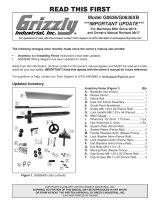
Introduction (Figure 1)
 
      
     

MODEL H7874
CERAMIC GUIDE SET FOR
G0531/G0566/G0568/G0569
INSTRUCTIONS

WARNING: NO PORTION OF THIS MANUAL MAY BE REPRODUCED IN ANY SHAPE
OR FORM WITHOUT THE WRITTEN APPROVAL OF GRIZZLY INDUSTRIAL, INC.

Figure 1
Figure
2
Inventory (Figure 2)
A. 
B. 
C. 
D. 
Tools Needed
• 
• 
• 
• 
Installing H7874 Upper Guides
1. 
2.        

Figure 3
Figure 3.

3. 
        

Tip Hold onto the guide post or it may drop
and damage the cast iron table.








6.        
      

Step 2 Figure 6
4.       


Figure 4


5.        
       


Figure 5
Figure 5.
Figure 6.

Figure 4.







7.       
       
Figure 7
8.        
  Figure 7  

 
     
Figure 8
&
$
&+

<jaaZiA^cZ
7aVYZ
<j^YZ7ZVg^c\
H^YZK^Zl
Figure 8. 

Figure 7.









Installing H7874 Lower Guides
1. 
2.        

3.   
Figure 10


9.       

10.       
Figure 7
11.       
  Figure 4   

Figure9
Note: The
1
/16" spacing is ideal, although with
larger blades it may not be possible. In such
cases, adjust the ceramic bearings as close
to the blade gullets as possible, while still
maintaining the proper support bearing spac-
ing adjustment.
<j^YZ
7ZVg^c\h
7aVYZ
%#%%)
IdeK^Zl
7aVYZ<j^YZ
Figure 9.

Note: 0.004" is approximately the thickness
of a dollar bill.
12     Figure 4 

4.        
      
  Figure 11    

Figure 11








Figure 10.








      
      
Figure 11     
        

7.       

8.        
       


9.       
       

10. 

11 


Figure 13
5. 
 Step 2  

6. 

Figure12
Figure 12.



Figure 13.
12.        
  
   
Figure 8  Page 2
13.       

14. 

15. 

Figure9 
Page 3
16.        



Adjusting Upper Support Bearings
1. 

2. 
3. 
Figure 3Page 1
     

Figure 14
4.      

5.       
   Figure 4  Page
2
6.       
      
        
Figure 15
Figure 14.

Figure 15.







Note: For a quick gauge, fold a crisp dollar bill
in half twice (four thicknesses of a dollar bill is
approximately 0.016") and place it between the
support bearing and the blade as shown in Figure
16
7. 

Figure 16.



Adjusting Lower Support Bearings
1. Steps 1-2Adjusting Upper Support
Bearings  Page 5
2. 
3. 

Figure 14
       


       
  

Figure 10 Page 3



4. 
   Figure
17
If you need help with your new item, call our Tech
Support at: (570) 546-9663.
5.       
        
Figure 15
Figure 16
6. 

7.        

Figure 17.




&
)
+
*
'
(
,
-
&,
&'
&)
.
&%
&&
&(
&+
&*
PART # DESCRIPTION REF PART # DESCRIPTION
1 PH7874001 KNURLED RING M22 X 2.5 10 PH7874010 UPPER GUIDE BLOCK
2 PH7874002 ADJUST SHAFT 11 PH7874011 UPPER GUIDE BLOCK SHAFT
3 PH7874003 RIVET 3.2 X 7.7 12 PH7874012 UPPER GUIDE SUPPORT BLOCK
4 PW07M FLAT WASHER 3MM 13 PH7874013 UPPER SPACING SLEEVE
5 PH7874005 BUSHING 14 PCAP02M CAP SCREW M6-1 X 20
6 PH7874006 LOCATOR 15 PB02M HEX BOLT M6-1 X 12
7 PH7874007 CERAMIC GUIDE RING 16 P6201ZZ BALL BEARING 6201ZZ
8 PH7874008 KNOB BOLT M6-1 X 15 17 PR03M EXT RETAINING RING 12MM
9 PSS01M SET SCREW M6-1 X 10
H7874 Upper Blade Guide Assembly


H7874 Lower Blade Guide Assembly
',
'*
'(
')
'&
''
'+
()
'.
'-
(%
(+
(*
((
(,
('
(&
REF PART # DESCRIPTION REF PART # DESCRIPTION
21 PH7874005 BUSHING 30 PH7874030 LOWER GUIDE BLOCK SHAFT
22 PH7874003 RIVET 3.2 X 7.7 31 PH7874031 LOWER GUIDE BLOCK PLATE
23 PW07M FLAT WASHER 3MM 32 PCAP01M CAP SCREW M6-1 X 16
24 PH7874008 KNOB BOLT M6-1 X 15 33 PCAP02M CAP SCREW M6-1 X 20
25 PH7874025 LOCATOR 34 PH7874034 KNOB BOLT M6-1 X 60
26 PH7874005 BUSHING 35 PR03M EXT RETAINING RING 12MM
27 PH7874007 CERAMIC GUIDE RING 36 P6201ZZ BALL BEARING 6201ZZ
28 PSS01M SET SCREW M6-1 X 10 37 PH7874013 UPPER SPACING SLEEVE
29 PH7874010 LOWER GUIDE BLOCK
  • Page 1 1
  • Page 2 2
  • Page 3 3
  • Page 4 4
  • Page 5 5
  • Page 6 6
  • Page 7 7
  • Page 8 8

Grizzly H7874 Owner's manual

Type
Owner's manual

Ask a question and I''ll find the answer in the document

Finding information in a document is now easier with AI