

1
Contents
Connecting the Units ................................ 1
Connecting the system ...................................... 3
Connecting the power cord (1) .......................... 5
Connecting the power cord (2) .......................... 7
Connecting the power cord (3) .......................... 9
When connecting to separately sold power
amp .......................................................... 11
When connecting with a rear view camera .... 13
When connecting the external video
component and the display ...................... 15
Installation ................................................ 17
Installing the hide-away unit .......................... 18
DIN Front/Rear-mount .................................... 18
DIN Front-mount ............................................ 18
DIN Rear-mount .............................................. 19
Fixing the front panel ...................................... 20
Installing the remote control unit .................... 20
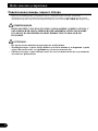
WARNING:
• To avoid the risk of accident and the
potential violation of applicable laws,
the front DVD or TV (sold separately)
feature should never be used while the
vehicle is being driven. Also, Rear
Displays should not be in a location
where it is a visible distraction to the
driver.
• In some countries or states the viewing
of images on a display inside a vehicle
even by persons other than the driver
may be illegal. Where such regulations
apply, they must be obeyed and this
unit’s DVD features should not be used.
• If this unit is used with more than a 6-ch
speaker system, be sure to connect the
yellow lead to the battery terminal
directly.
WARNING
LIGHT GREEN LEAD AT POWER CONNEC-
TOR IS DESIGNED TO DETECT PARKED
STATUS AND MUST BE CONNECTED TO
THE POWER SUPPLY SIDE OF THE PARK-
ING BRAKE SWITCH. IMPROPER CONNEC-
TION OR USE OF THIS LEAD MAY VIO-
LATE APPLICABLE LAW AND MAY
RESULT IN SERIOUS INJURY OR DAMAGE.
CAUTION:
• PIONEER does not recommend that
you install or service your display your-
self. Installing or servicing the product
may expose you to risk of electric shock
or other hazards. Refer all installation
and servicing of your display to autho-
rized Pioneer service personnel.
• Secure all wiring with cable clamps or
electrical tape. Do not allow any bare
wiring to remain exposed.
• Do not drill a hole into the engine com-
partment to connect the yellow lead of
the unit to the vehicle battery. Engine
vibration may eventually cause the insu-
lation to fail at the point where the wire
passes from the passenger compartment
into the engine compartment. Take
extra care in securing the wire at this
point.
• It is extremely dangerous to allow the
display lead to become wound around
the steering column or gearshift. Be sure
to install the display in such a way that
it will not obstruct driving.
• Make sure that wires will not interfere
with moving parts of the vehicle, such as
the gearshift, parking brake or seat slid-
ing mechanism.
• Do not shorten any leads. If you do, the
protection circuit may fail to work
properly.
• Do not install the display where it may
(i) obstruct the driver’s vision, (ii)
impair the performance of any of the
vehicle’s operating systems or safety
features, including air bags, hazard
lamp buttons or (iii) impair the driver’s
ability to safely operate the vehicle.
Connecting the Units

English
Español
Deutsch
Français
Italiano
Nederlands
PyÒÒÍËÈ
2
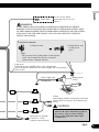
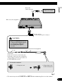
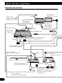
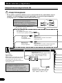
Note:
• Use this unit in other than the following condi-
tions could result in fire or malfunction.
— Vehicles with a 12-volt battery and negative
grounding.
— Speakers with 50 W (output value) and 4 ohm
to 8 ohm (impedance value).
• To prevent short-circuit, overheating or malfunc-
tion, be sure to follow the directions below.
— Disconnect the negative terminal of the battery
before installation.
— Secure the wiring with cable clamps or adhe-
sive tape. To protect the wiring, wrap adhesive
tape around them where they lie against metal
parts.
— Place all cables away from moving parts, such
as gear shift and seat rails.
— Place all cables away from hot places, such as
near the heater outlet.
— Do not pass the yellow cable through a hole
into the engine compartment to connect to a
battery.
— Cover any disconnected cable connectors with
insulating tape.
— Do not shorten any cables.
— Never cut the insulation of the power cable of
this unit in order to share the power to other
equipment. Current capacity of the cable is
limited.
— Use a fuse of the rating prescribed.
— Never wire the speaker negative cable directly
to ground.
— Never band together multiple speaker’s nega-
tive cables.
• Refer to the owner’s manual for details on
connecting the power amp and other units, then
make connections correctly.
• Control signal is output through blue/white cable
when this unit is powered on. Connect it to an
external power amp’s system remote control or
the vehicle’s auto-antenna relay control terminal
(max. 300 mA, 12 V DC). If the vehicle is
equipped with a glass antenna, connect it to the
antenna booster power supply terminal.
• Never connect blue/white cable to external power
amp’s power terminal. Also, never connect it to
the power terminal of the auto antenna.
Otherwise, battery drain or malfunction may
result.
• IP-BUS connectors are color-coded. Be sure to
connect connectors of the same color.
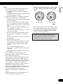
• This unit cannot be installed in a vehicle with-
out ACC (accessory) position on the ignition
switch.
Fig. 1
• Black cable is ground. This cable and other prod-
uct’s ground cable (especially, high-current prod-
ucts such as power amp) must be wired separate-
ly. Otherwise, fire or malfunction may result if
they are accidentally detached.
No ACC positionACC position
O
N
S
T
A
R
T
O
F
F
A
C
C
O
N
S
T
A
R
T
O
F
F
• Cord function may differ according to the
product, even if cord color is the same. When
connecting this system, be sure to check all
manuals and connect cords correctly.

3
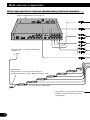
Connecting the Units
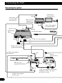
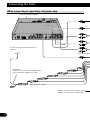
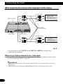
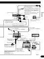
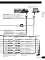
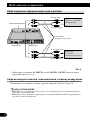
Connecting the system
Blue
Violet
6 m
6 m
Hide-away unit (supplied)
Black
Black
STAND ALONEIP BUS
25 pin cable (supplied with XDV-P6)
Depending on where you install,
this cable is not used.
Black
Black
AV-BUS cable (supplied
with XDV-P6)
Black
Black
White
IP-BUS input
(Blue)
AV-BUS cable (supplied
with TV tuner)
Blue
Antenna jack
Antenna cable (supplied)
6 m
AV-BUS input (Blue)
IP-BUS cable
(supplied with XDV-P6)
Blue
26-pin cable
(e.g. CD-CP300)
(sold separately)
Blue
Blue
Blue
Hide-away unit
(supplied with XDV-P6)
XDV-P6
(sold separately)
Hide-away unit
(supplied with
AVD-W1100V)
AVD-W1100V
(sold separately)
Pink
30-pin cable (supplied
with AVD-W1100V )

English
Español
Deutsch
Français
Italiano
Nederlands
PyÒÒÍËÈ
Fig. 2
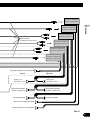
4
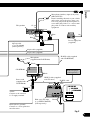
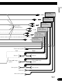
Violet
Blue
40 cm
15 cm
40 cm
1 m
This product
Power supply box
(supplied)
Blue
Black (chassis ground)
Connect to a clean, paint-free
metal location.
Fuse (3 A)
Yellow
Connect to the constant
12 V supply terminal.
IP-BUS cable
IP-BUS cable (supplied
with CD-BTB100)
Blue
Multi-CD player
(sold separately)
Black
Black
CD-BTB100
Microphone
(supplied with CD-BTB100)
Power cord
(supplied with
CD-BTB100)
Hide-away TV tuner
(e.g. GEX-P5700TVP)
(sold separately)
IP-BUS cable (supplied
with TV tuner)
Black
Blue
Black
Microphone/auxiliary input jack (3.5 ø)
(MIC/AUX IN)
Before installing this unit to your vehicle,
pull out the jack to the place where you
can easily plug in/out the microphone or
stereo mini plug cable. Use a stereo mini
plug cable to connect with auxiliary
equipment.
1.5 m
30-pin cable (supplied)
30-pin cable (supplied)
Optical cable
(e.g. CD-AD600)
(sold separately)

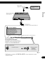
5
Connecting the Units
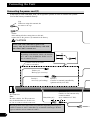
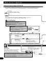
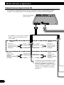
Connecting the power cord (1)
If this unit is used with more than a 6-ch speaker system, be sure to connect the yellow
lead to the battery terminal directly.
Note:
Depending on the kind of vehicle, the function
of 1* and 2* may be different. In this case, be
sure to connect 3* to 1* .
3*
1*
2*
Connect leads of the same
color to each other.
Red (3*)
Connect to terminal controlled by
ignition switch (12 V DC).
Red (2*)
Accessory (or back-up)
Yellow (1*)
Back-up (or accessory)
Yellow
After making all other connections to this unit,
connect this to the positive + terminal of the battery.
Cap
When not using this terminal, do
not remove the cap.
Blue/white (6*)
Blue/white (7*)
Connect to auto-antenna relay
control terminal
(max. 300 mA 12 V DC).
The pin position of the ISO connector will differ depending on the type of
vehicle. Connect 6* and 7* when Pin 5 is an antenna control type. In other
types of vehicles, never connect 6* and 7*.
ISO connector
Note:
In some vehicles, the ISO connector
may be divided into two. In this case,
be sure to connect to both connectors.
CAUTION
Attach a 20 A fuse immediately prior to the
battery. Also, use heat resistant battery cable with
more than 5 mm
2
sectional area.

6
English
Español
Deutsch
Français
Italiano
Nederlands
PyÒÒÍËÈ
Fuse resistor
Fuse resistor
Fuse (7.5 A)
Orange/white
Connect to lighting switch terminal.
Speaker leads
See the section “Connecting the
power cord (2)”.
Black (chassis ground)
Connect to a clean, paint-free
metal location.
Blue/white
Connect to system control terminal of the
power amp (max. 300 mA 12 V DC).
Yellow/black
If you use equipment with Mute function, wire
this lead to the Audio Mute lead on that piece of
equipment. If not, keep the Audio Mute lead free of
any connections.
This product
Power supply box
(supplied)
Fig. 3

7
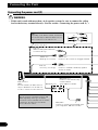
Connecting the Units
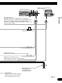
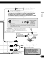
Connecting the power cord (2)
WARNING:
• If this unit is used with more than a 6-ch speaker system, be sure to connect the yellow
lead to the battery terminal directly. (See the section “Connecting the power cord (1)”).
Note:
Depending on the kind of vehicle, the function
of 3* and 5* may be different. In this case, be
sure to connect 2* to 5* and 4* to 3*.
1*
2*
4*
3*
5*
Connect leads of the same
color to each other.
Red (4*)
Connect to terminal controlled by ignition
switch (12 V DC).
Red (5*)
Accessory (or back-up)
Cap (1*)
When not using this terminal, do
not remove the cap.
Yellow (2*)
Connect to the constant 12 V supply terminal.
Yellow (3*)
Back-up (or accessory)
Blue/white (6*)
Blue/white
Connect to system control terminal of the
power amp (max. 300 mA 12 V DC).
Blue/white (7*)
Connect to auto-antenna relay
control terminal
(max. 300 mA 12 V DC).
The pin position of the ISO connector will
differ depending on the type of vehicle.
Connect 6* and 7* when Pin 5 is an antenna
control type. In other types of vehicles,
never connect 6* and 7*.
ISO connector
Note:
In some vehicles, the ISO connector
may be divided into two. In this case,
be sure to connect to both connectors.

8
English
Español
Deutsch
Français
Italiano
Nederlands
PyÒÒÍËÈ
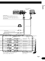
Fuse resistor
Fuse resistor
Fuse (7.5 A)
Orange/white
Connect to lighting switch terminal.
Speaker leads
Extension leads (6 m)
(supplied)
MID/FRONT
OUTPUT
Black (ground)
To vehicle (metal) body.
White:
White/black:
Gray:
Gray/black:
Green:
Green/black:
Violet:
Violet/black:
Front left +
Front left ≠
Front right +
Front right ≠
Rear left +
Rear left ≠
Rear right +
Rear right ≠
White
White/black
To hide-away unit
See the section “Connecting the
power cord (3)”.
Gray
Gray/black
Green
Green/black
Violet
Violet/black
This product
Power supply box
(supplied)
Connect in the case of audio output from car
speakers using the ISO connector.
Yellow/black
If you use equipment with Mute function, wire
this lead to the Audio Mute lead on that piece of
equipment. If not, keep the Audio Mute lead free of
any connections.
Fig. 4

9
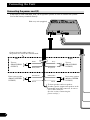
Connecting the Units
Connecting the power cord (3)
If this unit is used with more than a 6-ch speaker system, be sure to connect the yellow
lead to the battery terminal directly.
Hide-away unit (supplied)
+
≠
+
≠
+
≠
+
≠
Left Right
Tweeter
(FRONT HIGH
OUTPUT)
Front center speaker
(FRONT CENTER
OUTPUT)
Rear center speaker
(REAR CENTER
OUTPUT)
Tweeter
(FRONT HIGH
OUTPUT)
White
White/black
Gray
Gray/black
Black/white
Black
Black/white
Black
Connect when the audio settings of
this product are used in the network mode.
To front speakers and rear speakers.
If audio signal is output from speakers in the
automobile using ISO connector, be sure to
wire to ISO connector.
(See the section “Connecting the
power cord (2)”).

10
English
Español
Deutsch
Français
Italiano
Nederlands
PyÒÒÍËÈ
WARNING
Violet/white
See the section “When
connecting with a rear view
camera”.
Note:
• The position of the parking brake switch depends
on the vehicle model. For details, consult the
vehicle Owner’s Manual or dealer.
Connection method
1. Clamp the lead. 2. Clamp firmly with
needle-nosed
pliers.
Light green
Used to detect the ON/OFF status of the parking brake.
This lead must be connected to the power supply side of the parking
brake switch.
Power supply side
Ground side
Black (chassis ground)
Connect to a clean,
paint-free metal location.
Fuse (10 A)
Fuse (10 A)
Parking brake
switch
LIGHT GREEN LEAD AT POWER CONNECTOR IS DESIGNED TO DETECT
PARKED STATUS AND MUST BE CONNECTED TO THE POWER SUPPLY SIDE
OF THE PARKING BRAKE SWITCH. IMPROPER CONNECTION OR USE OF THIS
LEAD MAY VIOLATE APPLICABLE LAW AND MAY RESULT IN SERIOUS
INJURY OR DAMAGE.
Fuse (4 A)
Yellow
After making all other connections to this unit,
connect this to the positive + terminal of the
battery.
CAUTION
Attach a 20 A fuse immediately prior to
the battery. Also, use heat resistant
battery cable with more than 5 mm
2
sectional area.
Fig. 5

When connecting to separately sold power amp
11
Connecting the Units
Blue/white
Connect to system control terminal of the
power amp (max. 300 mA 12 V DC).
Hide-away unit (supplied)
System remote control
Connect when the audio settings of this
product are used in the network mode.
See the section “Connecting the power
cord (1)”.

English
Español
Deutsch
Français
Italiano
Nederlands
PyÒÒÍËÈ
Fig. 6
12
Power amp
(sold separately)
Power amp
(sold separately)
Power amp
(sold separately)
RCA cables
(sold separately)
Subwoofer
Front middle range
speaker
Rear speaker
Rear center speaker
Left Right
Power amp
(sold separately)
Power amp
(sold separately)
Power amp
(sold separately)
Front middle range
speaker
Rear speaker
Tweeter
Front center speaker
Tweeter

13
Connecting the Units
When connecting with a rear view camera
When using this product with a rear view camera, automatic switching to video from a
rear view camera when the gear shift is moved to REVERSE (R) position is possible.
WARNING:
• USE INPUT ONLY FOR REVERSE OR MIRROR IMAGE REAR VIEW CAMERA.
OTHER USE MAY RESULT IN INJURY OR DAMAGE.
CAUTION:
• The screen image may appear reversed.
• The rear view camera function is to be used as an aid for backing into a tight parking
spot. Do not use this function for entertainment purposes.
• Objects in the rear view may appear closer or more distant than they actually are.

English
Español
Deutsch
Français
Italiano
Nederlands
PyÒÒÍËÈ
14
Fig. 7
Hide-away unit (supplied)
15 cm
CAUTION
Fuse resistor
8m
Extension lead (supplied)
Rear view camera
RCA cable
(sold separately)
To video output
Pioneer recommends the use of
a camera which outputs mirror
reversed images, otherwise
screen image may appear
reversed.
Violet/white
Of the two lead wires connected to the
back lamp, connect the one in which the
voltage changes when the gear shift is in
the REVERSE (R) position.
Connection method
1. Clamp the lead. 2. Clamp firmly with
needle-nosed pliers.
See the section
“Connecting the power cord (3)”.
• It is necessary to set AV INPUT2 in SETUP when connecting the rear view camera.

15
Connecting the Units
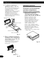
When connecting the external video component and the display
Fig. 8
• It is necessary to set AV INPUT1 or AV INPUT2 in SETUP according to the
connected AV component.
When using a display connected to rear video output
This product’s rear video output is for connection of a display to enable passengers in the
rear seats to watch the DVD or Video CD.
WARNING:
• NEVER install the display in a location that enables the Driver to watch the DVD or Video CD
while driving.
• NEVER connect rear audio output (REAR DISPLAY OUT) to sold separately power amp.
External video
component
(sold separately)
To audio inputs
To video input
RCA cables
(sold separately)
Hide-away unit
Video input 2 Video input 1
Display with
RCA input jacks
To audio outputs
To video output

English
Español
Deutsch
Français
Italiano
Nederlands
PyÒÒÍËÈ
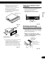
16
About video input 1
Depending on the external video component connected to this unit, video image may be
distorted. In this case, adjust the video image by switching the selector (selector is located
on the bottom of the hide-away unit as illustrated). Use a thin standard-tip screwdriver to
switch the selector.
Fig. 9

17
Installation
Note:
• Check all connections and systems before final
installation.
• Do not use unauthorized parts. The use of
unauthorized parts may cause malfunctions.
• Consult with your dealer if installation requires
drilling of holes or other modifications of the
vehicle.
• Do not install this unit where:
— it may interfere with operation of the vehicle.
— it may cause injury to a passenger as a result
of a sudden stop.
• Do not install the display where it may (i)
obstruct the driver’s vision, (ii) impair the perfor-
mance of any of the vehicle’s operating systems
or safety features, including air bags, hazard lamp
buttons or (iii) impair the driver’s ability to safely
operate the vehicle.
• The semiconductor laser will be damaged if it
overheats. Install this unit away from hot places
such as near the heater outlet.
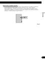
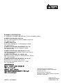
• Optimum performance is obtained when the unit
is installed at an angle of less than 30°.
Fig. 10
• Make sure you leave enough gap between the
dashboard and the LCD panel of this unit so the
LCD panel can be opened and closed without
contacting with the dashboard.
Fig. 11
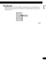
• The cords must not cover up the area shown in
the figure below. This is necessary to allow the
amplifires to radiate freely.
Fig. 12
• When installing make sure you leave ample space
(approx. 10 cm) in front of the exhaust fan outlet.
• When mounting the hide-away unit, make sure
none of the leads are trapped between the hide-
away unit and the surrounding metalwork or fit-
tings.
• Do not mount the hide-away unit near the heater
outlet, where it would be affected by heat, or near
the doors, where rainwater might splash onto it.
• Before drilling any mounting holes always check
behind where you want to drill the holes. Do not
drill into the gas line, brake line, electrical wiring
or other important parts.
• If the hide-away unit is installed in the passenger
compartment, anchor it securely so it does not
break free while the car is moving, and cause
injury or an accident.
• If the hide-away unit is installed under a front
seat, make sure it does not obstruct seat move-
ment. Route all leads and cords carefully around
the sliding mechanism so they do not get caught
or pinched in the mechanism and cause a short
circuit.
• Follow the instructions below when installing the
power supply box.
— Keep the power supply box as far away as
possible from any antenna cable.
— Do not install the power supply box where it
might obstruct safe driving.
Do not cover this area.
Hide-away unit
Dashboar
d
Leave
g
a
p
LCD
p
anel
30°

English
Español
Deutsch
Français
Italiano
Nederlands
PyÒÒÍËÈ
18
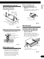
Installing the hide-away unit
Mounting with Brackets
Fig. 13
Mounting with Hook and Loop Fastner
Thoroughly wipe off the surface before
affixing the hook and loop fastner.
Fig. 14
DIN Front/Rear-mount
This unit can be properly installed
either from “Front” (conventional DIN
Front-mount) or “Rear” (DIN Rear-
mount installation, utilizing threaded
screw holes at the sides of unit chas-
sis). For details, refer to the following
illustrated installation methods.
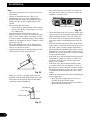
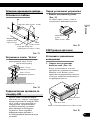
Before installing the unit
• Remove the mounting sleeve.
(Fig. 15)
Loosen the screws (2 mm × 3 mm) and
then remove the mounting sleeve.
Fig. 15
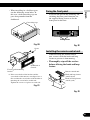
DIN Front-mount
Installation with the rubber bush
1. Decide the position of the side
brackets. (Fig. 16)
When installing in a shallow space,
change the position of side brackets. In
this case, stick concealing tape on parts
that protrude from the dashboard.
Fig. 16
Concealing tape
Side bracket
Flush surface screw (5 mm × 6 mm)
Mounting sleeve
Screw (2 mm × 3 mm)
Hook and loop fastner
(large) (hard)
Car mat or chassis
Hook and loop fastner
(large) (soft)
Hide-away unit
Screw
(4 mm × 8 mm)
Tapping screw
(4 mm × 12 mm)
Car mat or chassis
Drill 2 mm to 2.5 mm
diameter holes.
Bracket

19
Installation
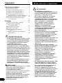
2. Install the unit into the dash-
board. (Fig. 17)
After inserting the mounting sleeve
into the dashboard, then select the
appropriate tabs according to the
thickness of the dashboard material
and bend them. (Install as firmly as
possible using the top and bottom tabs.
To secure, bend the tabs 90°.)
Fig. 17
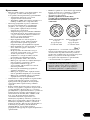
3. After installing the unit into the
dashboard, attach the trim ring.
(Fig. 18)
When attaching the trim ring, place the
narrow side of the frame downward.
Fig. 18
DIN Rear-mount
Installation using the screw holes on
the side of the unit
• Fastening the unit to the factory
radio mounting bracket. (Fig.
19) (Fig. 20) (Fig. 21)
Select a position where the screw holes
of the bracket and the screw holes of
this product become aligned (are fit-
ted), and tighten the screws at 2 places
on each side. Use any of binding
screws (4 mm × 3 mm), binding
screws (5 mm × 6 mm) or flush
surface screws (5 mm × 6 mm),
depending on the shape of the screw
holes in the bracket.
*1 Use binding screws (4 mm × 3 mm) only.
Fig. 19
*
1
*
1
*
1
*
1
Trim ring
Rubber bush
Screw
Dashboard
Side bracket
Screw (2 mm × 3 mm)
182
53
Mounting sleeve
Page is loading ...
Page is loading ...
Page is loading ...
Page is loading ...
Page is loading ...
Page is loading ...
Page is loading ...
Page is loading ...
Page is loading ...
Page is loading ...
Page is loading ...
Page is loading ...
Page is loading ...
Page is loading ...
Page is loading ...
Page is loading ...
Page is loading ...
Page is loading ...
Page is loading ...
Page is loading ...
Page is loading ...
Page is loading ...
-
 1
1
-
 2
2
-
 3
3
-
 4
4
-
 5
5
-
 6
6
-
 7
7
-
 8
8
-
 9
9
-
 10
10
-
 11
11
-
 12
12
-
 13
13
-
 14
14
-
 15
15
-
 16
16
-
 17
17
-
 18
18
-
 19
19
-
 20
20
-
 21
21
-
 22
22
-
 23
23
-
 24
24
-
 25
25
-
 26
26
-
 27
27
-
 28
28
-
 29
29
-
 30
30
-
 31
31
-
 32
32
-
 33
33
-
 34
34
-
 35
35
-
 36
36
-
 37
37
-
 38
38
-
 39
39
-
 40
40
-
 41
41
-
 42
42


Ask a question and I''ll find the answer in the document
Finding information in a document is now easier with AI
Related papers
-
Pioneer DVH-3100UB Installation guide
-
-
-
-
-
-
-
-
-
Other documents
-
Tefal PEPITO Owner's manual
-
Ferm TDM1010 - FPKB-16 Owner's manual
-
-
-
Philips MCD289/58 Quick Installation Guide
-
König & Meyer 21404-000-55 Datasheet
-
 Digital Media AVIC-D1 User manual
-
Analog Devices AD602 User manual
-
