Page is loading ...

WinSystems, Inc.
715 Stadium Drive
Arlington, TX 76011
http://www.winsystems.com
WinSystems
®
EPX-C380
Intel
®
ATOM
TM
EPIC Single Board Computer
PRODUCT MANUAL
Preliminary

110502 PRODUCT MANUAL EPX-C380 2
Revision Date Code ECO Number
110502
MANUAL REVISION HISTORY
P/N 400-0380-PP2
Preliminary

110502 PRODUCT MANUAL EPX-C380 3
TABLE OF CONTENTS
BEFORE YOU BEGIN 6
Visual Index - Top View (Connectors)
7
Visual Index - Top View (Jumpers & LEDs)
8
Visual Index - Bottom View 9
Jumper Reference 10
INTRODUCTION 13
FEATURES 13
System
14
Memory 14
FUNCTIONALITY 15
I/O Port Map
15
Interrupt Map 16
Watchdog Timer 17
Real-Time Clock/Calendar 18
CONNECTOR REFERENCE 19
POWER 19
J6 - Power and Reset 19
J8 - ATX Signals 19
JP2 - Power Supply Selection 20
BATTERY BACKUP 21
J4 - External Battery 21
VIDEO 22
J1 - ANALOG VGA 22
J7 - LVDS 23
J5 - Backlight Power 23
JP1 - Panel Power 24
AUDIO 25
J10 - HD Audio 25
SP1 - Speaker 26
SERIAL 27
J18 - COM1, COM2, COM3, COM4 27
USB 29
J9, J11 - USB 29
SERIAL ATA 30
J13, J16 - SATA 30
COMPACTFLASH 30
J501 - CompactFlash 30
1 MB SRAM 31
(Battery-Backed User Data Space) 31
Preliminary

110502 PRODUCT MANUAL EPX-C380 4
OPTIONAL SSD 33
ETHERNET 34
J21 - Ethernet 34
J25, J26 - Ethernet LEDs 35
STATUS LED 35
D14 - Status LED 35
DIGITAL I/O 36
J23, J24 - Digital I/O 36
JP9 - Digital I/O Power 36
Register Denitions (WS16C48) 37
Register Details 37
PC/104 BUS 39
J12, J15 - PC/104 39
PC/104-Plus BUS 40
J14 - PC/104-Plus 40
MiniPCI EXPRESS 41
J502 - MiniPCIe 41
BIOS SUPPLEMENTAL 42
BIOS SETTINGS STORAGE OPTIONS 65
CABLES 67
SOFTWARE DRIVERS 68
SPECIFICATIONS 69
MECHANICAL DRAWING 70
APPENDIX - A 71
BEST
PRACTICES 71
APPENDIX - B 75
POST
CODES 75
WARRANTY INFORMATION 80
Preliminary

110502 PRODUCT MANUAL EPX-C380 5
This page has been left intentionally blank.
Preliminary

110502 PRODUCT MANUAL EPX-C380 6
BEFORE YOU BEGIN
WinSystems offers best practice recommendations for using and handling WinSystems embedded PCs. These methods
include valuable advice to provide an optimal user experience and to prevent damage to yourself and/or the product.
YOU MAY VOID YOUR WARRANTY AND/OR DAMAGE AN EMBEDDED PC BY FAILING TO COMPLY WITH THESE
BEST PRACTICES.
Reference Appendix - A for Best Practices.
For any questions you may have on WinSystems products, contact our Technical Support Group at (817) 274-7553, Monday
through Friday, between 8 AM and 5 PM Central Standard Time (CST).
Please review these guidelines carefully and follow them to ensure
you are successfully using your embedded PC.
This product ships with a heat sink. Product warranty is void if the
heat sink is removed from the product.
Preliminary

110502 PRODUCT MANUAL EPX-C380 7
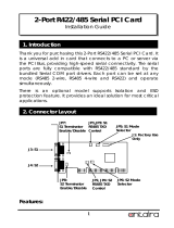
Visual Index - Top View (Connectors)
NOTE: The reference line to each component part has been drawn to Pin 1, and is also highlighted with a square, where applicable.
RESERVED - J3, J19, D12, D512, D513, D514, D515, D516, D517, D518, D519, D520
J8
ATX Power
J6
Power
J24
Digital I/O
(Ports 3/4/5)
J23
Digital I/O
(Ports 0/1/2)
J20
LPT
J18
Serial I/O
(COM 1/2/3/4)
J11
USB
(0/1/2/3)
J9
USB
(4/5/6/7)
J5
Backlight Power
J1
Analog VGA
J15
PC/104
(C/D)
J12
PC/104
(A/B)
J10
HD Audio
J16
SATA1
J7
LVDS
J4
External Battery
J21
Ethernet
J13
SATA0
J14
PC/104-Plus
J22
Intruder Detection
J2
Fan
Preliminary

110502 PRODUCT MANUAL EPX-C380 8
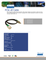
Visual Index - Top View (Jumpers & LEDs)
NOTE: The reference line to each component part has been drawn to Pin 1, and is also highlighted with a square, where applicable.
RESERVED - J3, J19, D12, D512, D513, D514, D515, D516, D517, D518, D519, D520
JP5
COM1
Termination
JP7
COM3
Termination
J26
Ethernet LEDs
(Port 1)
JP6
COM2
Termination
JP8
COM4
Termination
JP2
Power Supply
Selection
J25
Ethernet LEDs
(Port 2)
JP1
Panel Power
D14
Status LED
JP4
EEPROM Enable
JP3
CompactFlash
Master/Slave
JP9
Digial I/O Power
Preliminary

110502 PRODUCT MANUAL EPX-C380 9
Visual Index - Bottom View
NOTE: The reference line to each component part has been drawn to Pin 1, and is also highlighted with a square, where applicable.
RESERVED - J3, J19, D12, D512, D513, D514, D515, D516, D517, D518, D519, D520
J502
MiniPCIe
J501
CompactFlash
J500
Memory
Preliminary

110502 PRODUCT MANUAL EPX-C380 10
Jumper Reference
NOTE: Jumper Part# SAMTEC 2SN-BK-G is applicable to all jumpers. These are available in a ten piece kit from
WinSystems (Part# KIT-JMP-G-200).
JP5 - COM1, JP6 - COM2, JP7 - COM3, JP8 - COM4
JP5
2 4 6 8
□ □ □ □
□ □ □ □
1 3 5 7
JP6
2 4 6 8
□ □ □ □
□ □ □ □
1 3 5 7
JP7
2 4 6 8
□ □ □ □
□ □ □ □
1 3 5 7
JP8
2 4 6 8
□ □ □ □
□ □ □ □
1 3 5 7
JP4 - EEPROM
EEPROM Enable
CMOS Register Reset (only in G3 power mode) 1-2
SPI BIOS Write Protect 3-4
SPI BIOS Program Enable 5-6
CMOS EEPROM Enable (default) 7-8
CMOS EEPROM Disable 7 8
JP4
2 4 6 8
□ □ □ □
□ □ □ □
1 3 5 7
CompactFlash Master (default) 1-2
CompactFlash Slave 1 2
SSD Master 3-4
SSD Slave (default) 3 4
SSD Write Protect 5-6
SSD Program Enable (default) 5 6
Disable Ethernet Device 2 7-8
Enable Ethernet Device 2 (default) 7 8
JP3 - CompactFlash / Solid State Disk / Ethernet
JP3
2 4 6 8
□ □ □ □
□ □ □ □
1 3 5 7
RS-422 Termination and Biasing Resistors
TX (100): Places a 100Ω Resistor across the TX+/TX- pair 3-4
RX (100): Places a 100Ω Resistor across the RX+/RX- pair 7-8
TX(300):
Places a 100Ω Resistor from +5V to TX+ 1-2
Places a 100Ω Resistor between TX+ and TX- 3-4
Places a 100Ω Resistor from Ground to TX- 5-6
RS-485 Termination and Biasing Resistors
TX (100): Places a 100Ω Resistor across the TX/RX+/TX/RX- pair 3-4
TX/RX(300):
Places a 100Ω Resistor from +5V to TX/RX+ 1-2
Places a 100Ω Resistor between TX/RX+ and TX/RX- 3-4
Places a 100Ω Resistor from Ground to TX/RX- 5-6
Preliminary

110502 PRODUCT MANUAL EPX-C380 11
Jumper Reference (cont’d)
Avoid Simultaneous Jumpering of pins 1-2 and 2-3.
Misjumpering panel power causes damage to the
board and/or the Flat Panel.
Panel Power
5V
3.3V (default)
2-3
1-2
JP1 - Panel Power
AT Power 1-2, 3-4, 5-6, 7-8 (default)
ATX Power 1 2, 3 4, 5 6, 7 8
JP2 - Power Supply Selection
□ □
□ □
□ □
□ □
2
4
6
8
JP2
1
3
5
7
JP1
□ □ □
3 2 1
JP9 - Digital I/O VCC
+3.3V is provided at pin 49 of J23/J24 1-2
+5V is provided at pin 49 of J23/J24 2-3
No Power at Pin 49 of J23/J24 (default) OPEN
Avoid Simultaneous Jumpering of pins 1-2 and 2-3.
Misjumpering causes damage to the board.
JP9
□ □ □
3 2 1
5V
GND
+3V
Preliminary

110502 PRODUCT MANUAL EPX-C380 12
This page has been left intentionally blank.
Preliminary

110502 PRODUCT MANUAL EPX-C380 13
INTRODUCTION
This manual is intended to provide the necessary information regarding conguration and usage of the EPX-C380 single
board computer. WinSystems maintains a Technical Support Group to help answer questions not adequately addressed
in this manual. Contact Technical Support at (817) 274-7553, Monday through Friday, between 8 AM and 5 PM Central
Standard Time (CST).
FEATURES
CPU
Intel
®
ATOM™ N450 (1.66 GHz) single core or D510 (1.66 GHz) dual core
Compatible Operating Systems
Linux, Windows Embedded Standard, Windows XP, DOS, x86 RTOS
Memory
Up to 2 GB of DDR2 SDRAM (Socketed)
512 MB to 2 GB SSD (optional on-board Flash disk)
1 MB SRAM (optional battery-backed user data space) *SRAM is not applicable for model EPX-C380-S1-0.
BIOS
Phoenix
Video
Analog VGA or Flat Panel (simultaneous operation)
Analog VGA resolution up to SXGA 1400x1050
Flat Panel resolution up to SXGA 1400x1050
Up to 18-bits/pixel color panel
LVDS
SATA
2 SATA channels with speeds up to 300 Mbps
Ethernet
2 Intel
®
10/100/1000 Mbps Gigabit controller (one using PC82574 and one using ICH8M)
*Model EPX-C380-S1-0 includes one Ethernet controller for ICH8.
Digital I/O
48 GPIO Bidirectional lines (WS16C48)
Serial I/O
4 serial ports (RS-232/422/485) (2-RS232/422/285) (2-RS-232 for EPX-C380-S1-0).
*RS-422/485 on COM3 and COM4 are not supported for model EPX-C380-S1-0.
Line Printer Port
EPP/SPP
USB
8 USB 2.0 ports *USB(J11) is not applicable for model EPX-C380-S1-0.
Watchdog Timer
Adjustable up to 255 minute reset
CompactFlash
Types I & II
Audio
HD Audio
•
•
•
•
•
•
•
•
•
•
•
•
•
•
•
•
•
•
•
•
Preliminary

110502 PRODUCT MANUAL EPX-C380 14
System
The EPX-C380 is an Intel
®
ATOM™ Single Board Computer (SBC) which uses either a 1.66 GHz single core Intel N450
or 1.66 GHz dual core D510 processor paired with the ICH8M controller hub. This is an EPIC-compatible unit and
incorporates two 10/100/1000 Mbps Ethernet controllers, two SATA channels, 48 lines of digital I/O, four serial RS-
232/422/485 ports, watchdog timer, PS/2 keyboard and mouse controller, and LPT. The SBC also supports HD audio,
USB ports, and is equipped with a CompactFlash socket and MiniPCIe card socket.
Memory
The EPX-C380 board supports up to 2 GB DDR2 SODIMM system memory via an on-board socket located at J500.
Bus Expansion
PC/104-Plus
MiniPCIe *MiniPCIe not applicable for model EPX-C380-S1-0.
Industrial Operating Temperature
-40°C to 70°C
Form Factor
EPIC-compliant
4.50” x 6.50” (115 mm x 165 mm)
Additional Features
RoHS compliant
Real-time clock/calendar
•
•
•
•
•
•
•
Preliminary

110502 PRODUCT MANUAL EPX-C380 15
FUNCTIONALITY
I/O Port Map
Following is a list of I/O ports used on the EPX-C380. I/O addresses marked with a ** are generally unused and should
be the rst choice in I/O address selection for external I/O boards.
NOTE: The EPX-C380 uses a PnP BIOS resource allocation. Care must be taken to avoid contention with resources
allocated by the BIOS.
HEX Range Usage
020-03F 8259 Master
040-043 8254 PIT
04E-04F Reserved for on-board conguration
050-053 8254
060-06F Keyboard / Mouse Controller
070-07F CMOS RAM, Clock / Calendar
084-08F Internal / LPC
0A0-0BF 8259 Slave
0F0-0FF Math Co-processor
**100-11F Free
120-12F Digital I/O
**130-14F Free
150 Reserved for on-board conguration
**151-16F Free
170-177 PATA
178-1CF Free
1D0-1DF Legacy Watchdog (1D0-Enabled; 1D8 - Pet)
1E8-1EB Reserved for on-board conguration
1EC Interrupt Status Register
1ED Status LED
1EE-1EF Watchdog Timer Control
1F0-1FF PATA
**200-2AF Free
2B0-2DF Video Controllers
**2E0-2E7 Free
2E8-2EF COM4 (Default)
**2F0-2F7 Free
2F8-2FF COM2 (Default)
**300-375 Free
376-377 PATA
378-37B LPT (Default)
**37C-3AF Free
3B0-3BB Video Controllers
**3BC-3BF Free
3C0-3DF Video Controllers
**3E0-3E7 Free
3E8-3EF COM3 (Default)
**3F0-3F7 Free
3F6-3F7 PATA
3F8-3FF COM1 (Default)
564-568 Advanced Watchdog
CF8-CFF Internal Control Registers
Preliminary

110502 PRODUCT MANUAL EPX-C380 16
Interrupt Status Register - 1ECH
Bit 7 Bit 6 Bit 5 Bit 4 Bit 3 Bit 2 Bit 1 Bit 0
N/A N/A N/A N/A COM4 COM3 COM2 COM1
Note: A 1 will be read for the device(s) with an interrupt pending.
Interrupt Map
WinSystems does not provide software support for implementing the Interrupt Status
Register to share interrupts. Some operating systems, such as Windows XP and Linux,
have support for sharing serial port interrupts and examples are available. The user will
need to implement the appropriate software to share interrupts for the other devices.
Hardware Interrupts (IRQs) are supported for both PC/104 (ISA) and PCIe devices. The user must reserve IRQs in the
BIOS CMOS conguration for use by legacy devices. The PCIe/PnP BIOS will use unreserved IRQs when allocating
resources during the boot process. The table below lists IRQ resources as used by the EPX-C380.
IRQ0 18.2 Hz heartbeat
IRQ1 Keyboard
IRQ2 Chained to Slave controller (IRQ9)
IRQ3 COM2 *
IRQ4 COM1 *
IRQ5 COM3 *
IRQ6 COM4 *
IRQ7 LPT *
IRQ8 Real Time Clock
IRQ9 FREE **
IRQ10 Digital I/O
IRQ11 PCIe Interrupts
IRQ12 Mouse
IRQ13 Floating point processor
IRQ14 IDE
IRQ15 PCIe Interrupts
*
These IRQ references are default settings that can be changed by the user in the CMOS Settings
utility. Reference the Super I/O Control section under Intel.
**
IRQ9 is commonly used by ACPI when enabled and may be unavailable (depending on operating
system) for other uses.
*** IRQ15 is currently unavailable under the Windows operating systems.
Some IRQs can be freed for other uses if the hardware features they are assigned to are not being
used. To free an interrupt, use the CMOS setup screens to disable any unused board features or their
IRQ assignments.
Preliminary

110502 PRODUCT MANUAL EPX-C380 17
Watchdog Timer
The EPX-C380 features an advanced watchdog timer which can be used to guard against software lockups. Three
interfaces are provided to the watchdog timer. The Advanced interface is the most exible and recommended for new
designs. The other two interface options are provided for software compatibility with older WinSystems single board
computers.
Advanced
The watchdog timer can be enabled in the BIOS Settings by entering a value for Watchdog Timeout on the Intel → Super
I/O Control screen. Any non-zero value represents the number of minutes prior to reset during system boot. Once the
operating system is loaded, the watchdog can be disabled or recongured in the application software.
NOTE: It is recommended that a long timeout be used if the watchdog is enabled when trying to boot any operating
system.
The watchdog can be enabled, disabled or reset by writing the appropriate values to the conguration registers located
at I/O addresses 565h and 566h. The watchdog is enabled by writing a timeout value other than zero to the I/O address
566h and disabled by writing 00h to this I/O address. The watchdog timer is serviced by writing the desired timeout value
to I/O port 566h. If the watchdog has not been serviced within the allotted time, the circuit resets the CPU.
The timeout value can be set from 1 second to 255 minutes. If port 565h bit 7 equals 0, the timeout value written into I/O
address 566h is in minutes. The timeout value written to address 566h is in seconds if port 565 bit 7 equals 1.
Port Address Value Reset Interval
1EEH
00h DISABLED
01h 3 SECONDS
03h 30 SECONDS
05h 300 SECONDS
1EFH ANY RESET TIMER
Port Address Port Bit 7 Value Port Address Value Reset Interval
565H x 566H 00h DISABLED
565H 1 566H 03h 3 SECONDS
565H 1 566H 1Eh 30 SECONDS
565H 0 566H 04h 4 MINUTES
565H 0 566H 05h 5 MINUTES
Software watchdog timer PET = PORT 566H, write the timeout value.
Watchdog Timer Examples
Standard (requires changing the default I/O ranges within in the BIOS)
The watchdog can be enabled or disabled via software by writing an appropriate timeout value to I/O port 1EEH. See the
chart provided below.
Preliminary

110502 PRODUCT MANUAL EPX-C380 18
Real-Time Clock/Calendar
A real-time clock is used as the AT-compatible clock/calendar. It supports a number of features including periodic and
alarm interrupt capabilities. In addition to the time and date keeping functions, the system conguration is kept in CMOS
RAM contained within the clock section. A battery must be enabled for the real-time clock to retain time and date during a
power down.
Preliminary

110502 PRODUCT MANUAL EPX-C380 19
CONNECTOR REFERENCE
POWER
J6 - Power and Reset
Visual
Index
Power is applied to the EPX-C380 via the connector at J6. WinSystems offers the cable CBL-265-G-2-1.5 to simplify this
connection.
J6
PCB Connector: MOLEX 87427-1043 (J6)
Mating Connector: MOLEX 39-01-2105 (Housing)
MOLEX 39-00-0039 (Crimp)
9
6
7
8
1
2
3
4
5
1 0
G N D
- 1 2 V
+ 5 V
+ 5 V
+ 5 V S B
+ 3 . 3 V *
+ 1 2 V
G N D
G N D
P S O N
* - only connects to the PC/104-Plus connector
J8 - ATX Signals
Visual
Index
PCB Connector: MOLEX 22-11-2042 (J8)
Mating Connector: MOLEX 22-01-3047 (Housing)
MOLEX 08-55-0101 (Crimp)
J8
□ □ □ □
1 2 3 4
RESET
GND
PWRBTN
PWRGOOD
ATX signals for the power button, reset and power good are provided at J8. WinSystems offers the cable
CBL-265-G-2-1.5 to simplify this connection.
Preliminary

110502 PRODUCT MANUAL EPX-C380 20
The EPX-C380 supports either AT (standard power supply) or ATX type power supplies. Zero load supplies are
recommended. JP2 species the style of supply connected to the single board computer (SBC). An AT power supply is a
simple on/off supply with no interaction with the single board computer. Most embedded systems use this type of power
supply and it is the default setting.
ATX type power supplies function with a “soft” on/off power button and a +5 VSB (standby). If an ATX compatible power
supply is connected, JP2 should be set accordingly and a power button (momentary contact) connected between pin 3
(power button) and pin 2 (ground) of J8. The +5 VSB signal provides the standby voltage to the EPX-C380 but does not
power any other features of the board. When the power button is pressed, the EPX-C380 pulls PSON (Power Supply On)
low and the power supply turns on all voltages to the single board computer. When the power button is pressed again,
the BIOS signals the event so ACPI-compliant operating systems can be shutdown before the power is turned off. In ATX
mode, if the power button is held for 4 seconds, the power supply is forced off, regardless of ACPI. Since this is software
driven, it is possible that a software lockup could prevent the power button from functioning properly. For the BIOS to
report the ATX supply to ACPI-compatible operating systems, JP2 must be setup correctly.
JP2 - Power Supply Selection
Visual
Index
AT Power 1-2, 3-4, 5-6, 7-8 (default)
ATX Power 1 2, 3 4, 5 6, 7 8
□ □
□ □
□ □
□ □
2
4
6
8
JP2
1
3
5
7
Preliminary
/