Redfyre Classic Range Oil Cooker Owner's manual
- Category
- Cookers
- Type
- Owner's manual
This manual is also suitable for

Classic Range Cooker
OIL
Instructions for
Installation and Servicing
For use in Great Britain & Ireland
PR0655 Issue 2 (November 2006)
IMPORTANT
This appliance must be installed and commissioned by an experienced oil heating engineer.
Redfyre Cookers, Osprey Road, Sowton Industrial Estate, Exeter, Devon, England EX2 7JG
Tel: (01392) 444070 Fax: (01392) 444804 E-mail: [email protected]
A division of Gazco Ltd

2
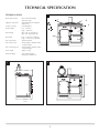
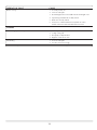
TECHNICAL SPECIFICATION
TECHNICAL DATA:
Burner Specification Don 8" Natural Draught
Vaporising Type
Appliance Type/Fuel Oil Fired Kerosene to BS2869
1988 Class 2
Country of Origin United Kingdom
Oil Flow Rates Low – 4ml/min.
High – 10ml/min.
Flue Draught Min. 0.02" wg (0.5mm wg)
Max. 0.04" wg (1.0mm wg)
Heat Input Low – 2.55kw (8.721 Btu/hr)
High – 6.37kw (21.734 Btu/hr)
Size of hot plates: 346mm diameter
Size of main oven: 507mm depth x 384mm width
x 310mm height
Size of warming oven 507mm depth x 384mm width
x 249mm height
Gross weight Approx. 397kg
Electrical Supply 230V 50Hz supplying
transformer 12VAC 1.5A
1
32
724mm
583mm
643mm
1007mm
940mm
17

3
INSTALLATION INSTRUCTIONS
The appliance is delivered fully assembled, with the exception of
the following items packed in a box in the Simmering Oven.
•
Set of Burner Shells
•
Astonish Cleaner
•
Burner Lid – 2 parts
•
Shelves (3)
•
Burner Ring
•
Cold Shelf
•
Vapour Chamber Lid
•
Roasting Dish (Lge)
•
Flue Collar & Filler Plate
•
Roasting Dish (Smll)
•
KBB Fire Valve
•
Cookbook
•
Set of Wicks
•
Instructions
To ensure optimum performance from this range cooker, it
must be installed and commissioned by a REDFYRE/OFTEC
approved engineer.
Installation must be carried out to accepted standards, and
comply with all regional and national regulations. Redfyre
Cookers will accept no responsibility or liability for any faults
arising from poor or incorrect installation.
Any alteration not approved by Redfyre Cookers could
invalidate the approval of the appliance and the operation of
its warranty, as well as adversely affecting the purchaser’s
statutory rights.
It is recommended that a qualified OFTEC engineer should
carry out servicing once, or preferably twice, a year.
It is a requirement under OFTEC regulations that the
installation is recorded on a CD 10 form (a copy is attached at
the end of this book). Once completed, a copy is to be given to
the end user and one copy sent to Gazco Ltd. Failure to do so
may invalidate the guarantee.
Installation must comply with these regulations:
The Building Regulations: Part J England and Wales; Part F,
Section III Scotland; Part L Northern Ireland; Part J Eire.
BS5440 Parts 1 & 2 installation of Flues and Ventilation.
BS5410 Part 1.
D.M.2. Installation in Timber Frame Buildings.
All OFTEC Codes of Practice.
Where a Standard or a Code of Practice is quoted, the current
version must be used.
1. IMPORTANT INFORMATION
3. DELIVERY
The location for the appliance must fit in with the layout and style
of the kitchen, and have:
access to services (oil and electricity);
enough space for the appliance, allowing access for
installation and maintenance;
a satisfactory flue;
a solid non-combustible hearth capable of supporting the
weight of the appliance.
4. LOCATION
2. COMPLIANCE
WARNING
CONTROL OF SUBSTANCES HARMFUL TO HEALTH
It is the responsibility of the user and installer to ensure that protective clothing is worn when materials known to be injurious to
health and safety are being handled.
•
Avoid inhalation when working with insulation materials such as ceramic board, glass fibre or mineral wool.
•
Use disposable protection for the eyes, skin and throat.
•
Use disposable gloves when handling fuels, fire cement and firebricks.
ALWAYS ENSURE THAT WORKING AREAS ARE WELL VENTILATED DURING INSTALLATION AND COMMISSIONING.
16
Burner soots up 1. Too little primary air.
2. Too low a flue pull.
3. Downdraught in flue. Fit suitable anti-downdraught cowl.
4. Vapourising Chamber lid not fully seated.
5. Shells not correctly seated.
6. Incorrect or contaminated fuel. Very little can cause
trouble. Clean out tank and refill with a new fuel.
COOKERS
Not reaching required temperature 1. Too little primary air.
2. To high a flue pull.
3. Flue partly or fully blocked.
4. High fire screw set too low.
Overheating 1. Too low a flue pull.
2. Low fire screw set too high.
Variations in temperature 1. Variations in flue draught. Fit suitable stabiliser.
EVIDENCE OF FAULT CAUSE
You need to allow at least a 3 mm gap between the
kitchen surfaces, cupboards or walls for expansion and
services.
4

4
This appliance is designed to operate with a Class 2 flue,
nominally 125mm (5") diameter. To ensure correct performance,
both flue and termination should conform to the relevant British
Standard.
NOTE: COMBUSTION TESTING, FLUE GAS ANALYSIS AND
DRAUGHT MEASUREMENT MUST BE CARRIED OUT ON SITE
BY THE APPROVED COMMISSIONING ENGINEER.
The quality of the flue is vital for satisfactory operation. A thorough
pre-installation check by a flue specialist is advisable. If an existing
flue is to be used, the specialist will advise on re-lining and the
correct choice of cowl or terminal for site wind conditions etc.
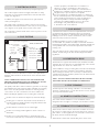
6. FLUE SYSTEMS
Typical Flue Arrangements
125mm (5") Diameter Flue
5
Approved anti-downdraught
flue terminal
Vermiculite
Clay liner
Sealing and
clamping plate
Min Height
toBend
=600mm
Vermiculite or
similar filter
Flexible flue liner
Closure plate
5" diameter flue
Cleaning hatch
NOTE: THESE DRAWINGS ARE SCHEMATIC REPRESENTATIONS ONLY
A minimum of 4 metres (15 feet) is required between cowl and
ground level.This ensures that the flue gases are vented into
relatively non-turbulent air, and will be less affected by nearby
buildings or trees etc. In certain circumstances, trees or other
obstructions may need to be removed.
Installation with flues in excess of 10M in height is not
recommended. Very tall flues are likely to exceed the maximum
flue draught specified in the technical data. High flue draughts can
cause problems with oven and hob temperatures and increase
running costs.
The cowl must be at least 1 metre above any obstruction within
600mm, and the siting of the flue should comply with OFTEC
regulations.
7. FLUE HEIGHT
Horizontal runs of greater than 450mm (18") should be avoided.
If the flue has to be offset, the recommended angle is 60° and the
legal minimum 45°. Never use a bend of 90°.
If the installation is using an existing flue, horizontal runs should be
avoided. A vertical rise of 600mm is the mandatory minimum
before turning into the flue. If it is necessary to exhaust into an
extended flue after the mandatory 600mm rise, the horizontal run
must not exceed 450mm.
NOTE: ALL FLUE CONNECTIONS MUST BE FULLY SEALED
AND INSPECTED BY THE INSTALLER ON COMPLETION.
8. HORIZONTAL RUNS
Before installing the appliance into an existing flue, check that:
•
the flue is clear of obstructions. Repair any structural damage.
•
the flue pipe is continuous. Any breaks in seals, flue liners etc.
must be rectified. A flexible steel liner (oil grade), BS4543 Parts
1 & 3 is highly recommended.
•
the flue diameter is uniform over its entire length.
•
the flue is not serving another appliance. Never connect to a
shared flue.
•
the flue is not constructed wholly of a single-skin pipe. This
must not be used under any circumstances. It has minimal heat
Annual inspection and cleaning of the flue is recommended.
Therefore a cleaning door, or some other means of access, should
be incorporated into the system.
9. FLUE CLEANING
The cooker must be installed on a non-combustible surface
designed to take its weight. For example, concrete slabs or similar.
10. HEARTH CONSTRUCTION
Allow 15mm to the rear of the unit for the circulation of air and
the escape of cooking vapours. Do not tile down as far as the top
plate surface – if the top plate has to be removed at some time in
the future, the tiles would be damaged.
Allow 20mm to either side. Vertical filler pieces can be used.
11. CLEARANCE TO COMBUSTIBLES
15
Black stain around any door 1. Too little primary air.
2. Too low a flue pull.
3. Downdraught in flue. Fit suitable anti-downdraught cowl.
4. Flue partly or fully blocked.
5. High fire screw set too high.
Burner carbons up after short period 1. Low fire screw set too low.
2. Oil Control filter blocked. Remove and clean with boiling
water and dry thoroughly before replacing.
3. Incorrect or contaminated fuel. Very little can cause
trouble. Clean out tank and refill with a new fuel.
Unable to light burner 1. Control metering stem slot obstructed. To clear, turn
Control Knob from OFF to full ON several times.
2. Oil Control filter blocked. Remove and clean with boiling
water and dry thoroughly before replacing.
3. Metering stem in oil control sticking. Replace control.
4. Fuel inlet blocked. Service.
5. Oil depth in burner base too shallow.
6. Oil level in tank too low.
7. Air lock in oil line tank – burner – control.
8. Incorrect or contaminated fuel. Very little can cause
trouble. Clean out tank and refill with a new fuel.
9. Electrical supply failed or turned off. Check power supply. If there is
a power cut, switch control to manual. See User’s Instructions.
Burner goes out after burning 1-2 hours 1. Too little primary air.
2. Downdraught in flue. Fit suitable anti-downdraught cowl.
3. Low fire screw set too low.
4. Control metering stem slot obstructed. To clear, turn Control
Knob from OFF to full ON several times.
5. Fuel inlet blocked. Service.
6. Oil depth in burner base too shallow.
7. Oil level in tank too low.
8. Air lock in oil line tank – burner – control.
9. Incorrect or contaminated fuel. Very little can cause
trouble. Clean out tank and refill with a new fuel.
Burner goes out for no apparent reason 1. Too little primary air.
2. Downdraught in flue. Fit suitable anti-downdraught cowl.
3. Flue partly or fully blocked.
4. Low fire screw set too low.
5. Control metering stem slot obstructed. To clear, turn
Control Knob from OFF to full ON several times.
6. Trip lever operated.
7. Oil Control filter blocked. Remove and clean with boiling
water and dry thoroughly before replacing.
8. Fuel inlet blocked. Service.
9. Oil level in tank too low.
10. Air lock in oil line tank – burner – control.
11. Incorrect or contaminated fuel. Very little can cause trouble.
Clean out tank and refill with a new fuel.
12. Electrical supply failed or turned off. Check power supply. If there is
a power cut, switch control to manual. See User’s Instructions.
EVIDENCE OF FAULT CAUSE
retention properties, and will lead to an overall loss of
efficiency, as well as condensation in flue and ovens.
•
vermiculite backfill, or the equivalent, is used whenever a
flexible liner is installed. It must be sealed top and bottom.
•
salt-glazed clay or pre-cast liners are acceptable.
•
the most appropriate cowl depends entirely on conditions at
the site. Several may have to be tried before one is found that
gives good all-year performance. In some circumstances it
may not be possible to entirely exclude downdraughts
caused by surrounding buildings or trees, so fit an anti-
downdraught cowl, preferably of the O-H type.
A ‘Chinaman’s Hat’ is not sufficient.
All electrical work must be carried out by competent persons.
This cooker requires an electrical supply 230V 50Hz. A 3Amp
fused spur is to be positioned within 90cm of the LH side of the
cooker, See diagram 14.
In addition, the supply can be wired in via an optional timer
control, see diagram 14.
This supply needs a transformer which connects to the oil valve
thermostat control fitted inside the cooker. Easy access is provided
via a magnetic access panel on the LH side of the cooker.
The cooker has a manual overide in the event of a power cut. See
User’s Instructions.
5. ELECTRICAL SUPPLY

5
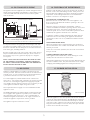
It is important that the oil supply pipe and the height of the tank
are sufficient to enable 0.8 litres of oil per hour to pass freely into
the burner. Calculate the size taking into account the total friction
losses in the pipe, including bends etc.
Run the oil supply pipe to the rear LH side of the cooker, where it
will join with the Preformed 8mm Feed Pipe, which connects to
the Oil Valve. Easy access is gained to this pipe via a magnetic
access panel.
NOTE: A FUEL SHUT-OFF VALVE MUST BE FITTED AS CLOSE
TO THE APPLIANCE AS POSSIBLE – AND BE ACCESSIBLE AT
ALL TIMES. IT SHOULD BE CLOSED WHEN THE PROPERTY IS
VACANT FOR ANY LENGTH OF TIME.
5
Oil tank and pipe installation
A = 450mm minimum height above the Cooker Oil Control Valve
H= Head of oil not more than 3m above the Cooker Oil Control Valve
Whenever a flued appliance is installed, a permanent air vent
must be provided. It must be located to take its air either from an
external source, or from an adjacent room which itself must have
a permanent external air vent of at least the same size.
For oil fired appliances, British Standard Code of Practice BS
5410: Part 1: 1997 requires that combustion air must be provided
into the room containing the appliance through purpose made
non-closable openings, having a total free area of 550mm
2
per kW
of the appliance maximum output rating above 5 kW.
This requirement does not apply if a room sealed balanced flue
appliance is used.
The Building Regulation for England, Wales, Scotland require that
an air supply to each appliance is provided, in accordance with
the requirement of BS 5410: Part 1: 1997. In the Republic of
Ireland, the Regulations advise that an air supply of 550mm
2
for
each kW of appliance output above 5 kW is provided.
This appliance requires a minimum of 755m
2
.
13. AIR SUPPLY
15. BURNER INSTALLATION
When the extractor is elsewhere in the building – all doors,
windows and additional ventilation openings must be closed, and
internal doors left open. The extractor should then be run at
maximum speed. As soon as the normal airflow pattern has been
established, the appliance should be set to maximum.
Combustion condition readings should then be taken with and
without the extractor fan running. The appliance should work
satisfactorily in either case. If not, additional ventilation must be
provided.
VENTILATION RESTRICTIONS
Where the appliance has a Vaporising Burner, the mechanical
extract rate from the area in which it is installed must not exceed
20 litres per second.
In the case of a Pressure Jet Burner, the rate must not exceed 40
litres per second.
OTHER INTERFERENCE WITH AIR SUPPLY
Other appliances like tumble driers, which discharge air to the
outside, have the same effect as extractor fans.
Other heating appliances in the same area using different fuels can
also have an adverse effect. They must have their own air supply
complying with Building Regulations for that particular fuel.
Appliances with the ability to extract air should not be located in
the same room as the oil-fired Range Cooker. If this proves to be
impracticable, then additional air inlets to should be provided to
compensate. A Flue Draught Interference Test will determine
whether or not there is an adequate air supply.
FLUE DRAUGHT INTERFERENCE TEST
When the extractor is in the same room as the appliance – all
doors, windows and additional ventilation openings to the room
must first be closed.
14. FLUE DRAUGHT INTERFERENCE
6
Burner Assembly
When the appliance is in its final position and has been levelled,
connect the 10mm Oil Feed Pipe to the KBB Remote Acting Fire
Valve, 8mm connection to the Preformed Feed Pipe on the LH
side of the cooker, and then to the inlet of the Oil Control Valve.
Purge the Oil Feed Pipe to remove air locks, then open all valves
to allow oil into the Oil Control Valve.
The appliance must be supplied by an oil tank and pipework of an
OFTEC approved standard, and installed to current OFTEC Codes
of Practice. Mild steel tanks should conform to BS541, plastic
tanks to OFT100.
12. OIL TANK SUPPLY PIPING
14
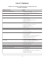
FAULT FINDING
GENERAL FAULT FINDING CHART FOR SINGLE, COMBINATION AND
DOUBLE OIL BURNERS
Trip/Reset lever operates repeatedly 1. Oil level in control too high.
2. Top of tank over 10 feet above oil control unit.
Yellow flame on high fire only 1. High fire screw set too high.
2. Burner out of level.
Yellow flame on low fire only 1. Low fire screw set too low.
2. Burner out of level.
Yellow flame at all Control Knob positions 1. Too much primary air.
2. Too little secondary air.
3. Vapourising Chamber lid not fully seated.
4. Shells not correctly seated.
5. Burner out of level.
Yellow flame at one point of burner only 1. Wicks incorrectly positioned or upside down.
2. Vapourising Chamber lid not fully seated.
3. Shells not correctly seated.
4. Lighting flap not correctly seated.
5. Burner out of level.
Flame funnelling at centre of burner 1. Wicks incorrectly positioned or upside down.
Flame appears to leave top of burner 1. Too little primary air.
2. Too low a flue pull.
3. Flue partly or fully blocked.
Burner Popping 1. Too little primary air.
2. Too much secondary air.
3. Too low a flue pull.
4. Downdraught in flue. Fit suitable anti-downdraught cowl.
5. Wicks incorrectly positioned or upside down.
6. Oil depth in burner base too deep.
7. Vapourising Chamber lid not fully seated.
Burner surging 1. Variations in flue draught. Fit suitable stabiliser.
2. Fuel inlet overheating. Insulate with fireproof material.
3. Oil depth in burner base too deep.
Impossible to set high fire high enough 1. Too little primary air.
2. Flue partly or fully blocked.
Impossible to set high fire low enough 1. Too much primary air.
Impossible to set low fire high enough 1. Too little primary air.
Impossible to set low fire low enough 1. Too much primary air.
Oil smell apparent 1. Too little primary air.
2. Too low a flue pull.
3. Downdraught in flue. Fit suitable anti-downdraught cowl.
4. Flue partly or fully blocked.
5. High fire screw set too high.
EVIDENCE OF FAULT CAUSE

6
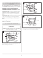
NOTE: AVOID KINKING IN THE OIL FEED PIPE, IT CAUSES AIR
LOCKS. ALWAYS RUN THE PIPE TO A LOW POINT, THEN
PROVIDE A GRADUAL UPWARD SLOPE TO THE BURNER.
Open the Burner Door, and remove the Burner Cover.
Adjust the front support levelling screws of the Burner Assembly
until it is level in all directions by using a Cross Test Level. Then
tighten the locknuts on the levelling screws, and re-check for level.
Check that the oil depth in the burner base is between 5 to 6mm.
Correct if necessary by adjusting the position of the Oil Control
Valve.
NOTE: The Burner Base must be level in all directions.
It is a requirement under OFTEC regulations that the
installation is recorded on a CD 10 form (a copy is attached at
the end of this book). Once completed, a copy is to be given to
the end user and one copy sent to Gazco Ltd. Failure to do so
may invalidate the guarantee.
Complete this form now.
13
SERVICE RECORDS
1ST SERVICE 2ND SERVICE
Date of Service: . . . . . . . . . . . . . . . . . . . . . . . . . . . . . . . . Date of Service: . . . . . . . . . . . . . . . . . . . . . . . . . . . . . . . .
Next Service due:. . . . . . . . . . . . . . . . . . . . . . . . . . . . . . . Next Service due:. . . . . . . . . . . . . . . . . . . . . . . . . . . . . . .
Signed: . . . . . . . . . . . . . . . . . . . . . . . . . . . . . . . . . . . . . . . Signed:. . . . . . . . . . . . . . . . . . . . . . . . . . . . . . . . . . . . . . .
Dealer’s Stamp Dealer’s Stamp
3RD SERVICE 4TH SERVICE
Date of Service: . . . . . . . . . . . . . . . . . . . . . . . . . . . . . . . . Date of Service: . . . . . . . . . . . . . . . . . . . . . . . . . . . . . . . .
Next Service due:. . . . . . . . . . . . . . . . . . . . . . . . . . . . . . . Next Service due:. . . . . . . . . . . . . . . . . . . . . . . . . . . . . . .
Signed: . . . . . . . . . . . . . . . . . . . . . . . . . . . . . . . . . . . . . . . Signed:. . . . . . . . . . . . . . . . . . . . . . . . . . . . . . . . . . . . . . .
Dealer’s Stamp Dealer’s Stamp
5TH SERVICE 6TH SERVICE
Date of Service: . . . . . . . . . . . . . . . . . . . . . . . . . . . . . . . . Date of Service: . . . . . . . . . . . . . . . . . . . . . . . . . . . . . . . .
Next Service due:. . . . . . . . . . . . . . . . . . . . . . . . . . . . . . . Next Service due:. . . . . . . . . . . . . . . . . . . . . . . . . . . . . . .
Signed: . . . . . . . . . . . . . . . . . . . . . . . . . . . . . . . . . . . . . . . Signed:. . . . . . . . . . . . . . . . . . . . . . . . . . . . . . . . . . . . . . .
Dealer’s Stamp Dealer’s Stamp
7TH SERVICE 8TH SERVICE
Date of Service: . . . . . . . . . . . . . . . . . . . . . . . . . . . . . . . . Date of Service: . . . . . . . . . . . . . . . . . . . . . . . . . . . . . . . .
Next Service due:. . . . . . . . . . . . . . . . . . . . . . . . . . . . . . . Next Service due:. . . . . . . . . . . . . . . . . . . . . . . . . . . . . . .
Signed: . . . . . . . . . . . . . . . . . . . . . . . . . . . . . . . . . . . . . . . Signed:. . . . . . . . . . . . . . . . . . . . . . . . . . . . . . . . . . . . . . .
Dealer’s Stamp Dealer’s Stamp
9TH SERVICE 10TH SERVICE
Date of Service: . . . . . . . . . . . . . . . . . . . . . . . . . . . . . . . . Date of Service: . . . . . . . . . . . . . . . . . . . . . . . . . . . . . . . .
Next Service due:. . . . . . . . . . . . . . . . . . . . . . . . . . . . . . . Next Service due:. . . . . . . . . . . . . . . . . . . . . . . . . . . . . . .
Signed: . . . . . . . . . . . . . . . . . . . . . . . . . . . . . . . . . . . . . . . Signed:. . . . . . . . . . . . . . . . . . . . . . . . . . . . . . . . . . . . . . .
Dealer’s Stamp Dealer’s Stamp

7
Fit the Burner wicks, and check that the ‘cut-outs’ face downwards
and line up with the radial oilways in the Burner Base.
Now fit the Vapour Chamber Lid with its machined face
downwards, and turn, pressing down to get a mechanical seal.
Also check that each Perforated Shell Assembly has a near-airtight
seal with the Burner Base – and that the seams are arranged
approximately at right angles to each other, with the Lighting Port
at the bottom facing forward. Take care not to trap a wick thread
between the Shell and the Base.
16. FITTING THE BURNER WICKS
8
Wicks
Cross Ports
Galleries
Open the Oil Control Box Cover.
After making sure that all valves have been opened, press down
the Trip/Reset Lever, and turn the Oil Control Knob to the
‘Number 6’ setting.
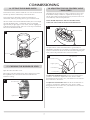
17. CHECKING THE BURNER OIL LEVEL
Oil Control Knob
Trip/Reset Lever
8
18. ADJUSTING THE OIL CONTROL VALVE
– BM30 SERIES
The BM30 Oil Control Valve is a safety component, and so must
be handled carefully. Installation, adjustment and servicing can
only be performed by authorised personnel, and must conform to
Local Authority codes and requirements.
NOTE: BEFORE ADJUSTING THE OIL CONTROL VALVE,
CHECK THE VALVE AND FILTER FOR CONTAMINATION.
9
Control rail
Control Oil Knob
The performance of the Oil Control Valve is governed by an
adjustable Control Rail. It is mounted on a toothed rack, moved by
a pinion connected to the Oil Control Knob. Before adjusting the
rates, remove the punched section of the Cover Plate.
Control Valve Adjustment
10
Low fire position
Control knob (A)
High fire position
Low fire limit screw (F)
High and Low fire adjusting
screw position (E)
Actuating pin
To adjust the minimum flow rate turn the Oil Control Knob to
‘position 1’ and turn the Adjustment Screw, which is visible
through the knockout in the cover, anti-clockwise to increase the
flow, clockwise to decrease it.
To adjust the maximum flow rate turn the Oil Control Knob to
‘position 6’ and turn the Adjustment Screw, which is visible
through the knockout in the cover, anti-clockwise to increase the
flow, clockwise to decrease it.
COMMISSIONING
12
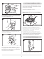
Carefully remove the mineral wool insulation to reveal the
Cleaning Door, then remove it.
Remove both top Flueway Cover Plates – and thoroughly clean all
combustion products from the flueways with a wire brush.
Replace the Cover Plates, making sure the gaskets are sound and
form a gas-tight joint. Replace the insulation.
Check that the integral Draught Stabiliser is free from obstruction
and can move freely.
Thoroughly clean the passages across the top of the cooker before
the Boiling and Simmering Hotplates are replaced.
24
Removal of the mineral
wool insulation
25
Removal of the flueway cover plate
25. RE-ASSEMBLY
First, replace the Burner Assembly in the Combustion Chamber
and lightly tighten the 2 retaining nuts.
Using a Cross Test Level, make sure the base is level in all
directions by adjusting the Jacking Screws – then tighten the two
retaining nuts. Re-check that the Burner is level.
Re-connect the Oil Supply Pipe to the Oil Control Valve, checking
all joints for leaks.
Allow oil to enter the Burner and check the oil depth is between
5 to 6mm.
Replace the Vapour Chamber Lid, and turn, pressing down, to get
a mechanical seal.
Insert new wicks, making sure the cut-outs are facing downwards
and in line with the radial ports.
Fit the Burner Shells, starting with the inner one and working
outwards. Arrange the seams at 90˚ to one another, with the outer
shell Lighting Port facing forwards. Check that each shell is
accurately located on its spigot, and has not trapped a strand of
wick material.
Fit the Cast Iron Flame Ring, taking care not to disturb the Outer
Shell, then fit the Burner Lids.
Replace the Boiling and Simmering Hotplates, using the tool
provided. When in place, tighten the fixing screws – making sure
both hobs are uniformly bedded on the rope seal, and level after
final tightening.
Replace the Inner Control Box Assembly, and re-fit the Tempomat
to the Oil Control Valve.
Re-fit the Oil Control Box Casing, and the control knobs.
Turn on the electrical supply, press the Safety Button to turn on
the oil supply – allowing 10-15 minutes for sufficient oil to enter
the Burner.
Then turn the Oil Control Knob to ‘High +’ setting, and switch on
the Thermostat.
Lift the Lighting Port Cover, light the Burner, and then replace the
Burner Cover.
With the Thermostat at the mid-position, let the cooker get back
up to its working temperature.
The Servicing Procedure is now complete.

8
19. CHECKING AND ADJUSTING BURNER
FLOW RATES
After making sure that the Burner is level, and that the oil is at the
correct depth, disconnect the feed pipe from the Oil Control Valve
to the Burner and measure the flow rate by the Drip Feed Method.
NOTE: ALLOW 10 MINUTES FOR THE FLOW RATE TO
STABILISE BEFORE MEASURING. AFTER RESETTING, ALLOW
2 MINUTES BEFORE THE NEXT MEASUREMENT.
To check the low setting - turn the Oil Control Knob on the Oil
Control Valve to ‘position 1’, and check the flow. It should be
4.0ml/min. If it needs adjusting, turn the Low Setting Screw in
the direction shown on the cover plate to increase or decrease
the flow.
To check the high setting - turn the Oil Control Knob to ‘position
6’, allow time for the flow to settle, then check. It should be
10.0ml/min. If it needs adjusting, turn the High Setting Screw in
the direction shown on the cover plate to increase or decrease
the flow.
When adjusting the burner flow rates, the screws musrt only be
turned a quarter of a turn at a time and the flow allowed to
stabilise before turning further.
20. LIGHTING THE OIL BURNER
11
Burner Door
Burner Cover fixing nut
Burner
Cover
WARNING
NEVER try to re-light a hot burner! The burner MUST
be cool before you turn on the oil!
Open the Burner Door, then unscrew large hexagonal nut on the
Burner Cover using the tool provided.
Lift up the Controls cover. Push down the Safety Button to turn on
the oil supply, and turn the Oil Control Knob to ‘High +’.
13
Oven Heat
Thermostat
Safety Button
Power Indicator
Oil control
valve cover
Thermostat
Over-ride
Oil Control
Lift the Oil Control Valve Cover
Lift up the Burner Cover, and remove it.
12
Inner burner door
21
11
23. CLEANING BURNER AND FILTERS
24. CLEANING THE FLUEWAYS
Remove the Burner Cover by releasing the hexagonal nut with the
tool provided, and lifting the door clear.
Carefully dismantle the Burner, Flame Ring, Burner Lids, Shells,
Vapour Chamber Lid, and Wicks.
Check that the oil supply has been isolated, then disconnect the
Oil Supply Pipe from the Oil Control Valve, avoiding spillage.
Remove the Burner Assembly by undoing the two nuts securing it
to the Combustion Chamber and lifting it out.
Remove the right-hand panel in the Combustion Chamber.
Thoroughly clean soot deposits from all burner components.
Remove the Oil Filter Element from the Oil Control Valve, wash
out with clean kerosene, and re-assemble. Check that the
neoprene gasket makes a leak-proof seal.
In exceptional cases, it may be necessary to remove the Oil
Control Valve metering stem. This must be done with great care,
avoiding any damage to the slot – which must be cleaned with a
wooden cocktail stick, or similar. Never use anything metallic, as it
could increase the slot width and seriously affect flow rates.
Clean the Burner Base thoroughly, paying particular attention to
the cross ports and galleries. Make sure the annular shell location
spigots are clean and undamaged, and that the Vapour Chamber
Lid seating is flat and unmarked.
Check the machined face of the Vapour Chamber Lid to make
sure the surface is flat and free of inclusions.
Make sure the carbon leg (fuel inlet) is free from any carbon
deposits. When re-assembling it into the Burner Base do not use
PTFE tape as a seal, always use a jointing compound like Foliac.
Withdrawal of the assembly
20
19
Burner Door
Burner Cover fixing nut
Burner
Cover
22
23
Removal of the
right side panel
Vapour Chamber Lid
machined face
Annular shell location
spigots
Vapour Chamber Lid
seating

9
Leave the Oil Control Knob at ‘High +’, and turn the Thermostat
to its mid position. Shut the Burner Door, and leave for 20
minutes until the burner is hot, then reset the Thermostat to its
maximum ‘Hot +’ position.
The Burner will gradually increase its oil flow rate and raise the
temperature of the oven, taking about two and a half hours to
reach 200˚C (400˚F). Turn the Thermostat to the mid position,
and the oven will maintain its temperature. When cooking is not
required, the Thermostat can be turned to its minimum
‘Warm –‘ setting.
When the appliance is first fired, it may give off a slight odour for
a short time. This is normal, and no cause for concern.
15
Insert a lit taper through the lighting port
Lighting port
Lighting port
cover
Using the Sampling Hole in the front of the Flue Hood Assembly,
sample the flue products with a Baccarach Smoke Pump and
check the flue draught. Adjust the draught divertor to give the
required flue draught. See Technical Specification on page 2.
All readings should give a Smoke Number of 0-1 at both low rate
and high rate.
NOTE: NOW COMPLETE THE COMMISSIONING CHECKLIST
ON THE FOLLOWING PAGE – AND MAKE SURE THE USER IS
FAMILIAR WITH BOTH THE OPERATION OF THE APPLIANCE,
AND THE SAFETY MEASURES.
It is a requirement under OFTEC regulations that the
comissioning is recorded on a CD 11 form, available from
Oftec. Once completed, a copy is to be given to the end user
and one copy sent to Gazco Ltd. Failure to do so may invalidate
the guarantee.
21. TESTING BURNER SMOKE
14
MAINS IN
SWITCHED OUT
Optional Timer Control
3A Fused Spur
240V
12VAC
50Hz
Oil Valve Thermostat
Oil Valve
Thermostat
with detail
Indicator
Neon
12VAC
T/Stat
Element
1 2 3 4
Plug In
Transformer
Less than 900mm
1 2 3 4
Connect the secondary leads from the 12 Volt Transformer to the
Tempomat (oil valve thermostat activator). See wiring diagram
above.
Plug the 12 Volt Transformer into the Fused Spur provided and
turn on the electricity.
If the optional Timer Control is fitted, please follow the
instructions supplied with the Timer for setting procedures.
Turn the Thermostat to its maximum position and allow 15
minutes for the oil to enter the Burrner Base.
Lift the hinged cover of the Lighting Port on the front of the
burner, and light the wick.
Replace the Lighting Port Cover, then the Burner Cover. The
hotplate covers must also be closed, to conserve heat.
10
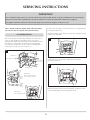
SERVICING INSTRUCTIONS
Remove the Boiling and Simmering Hotplates. First release the 3
screws on each hotplate, and wind the plate out to expose
approximately 30mm. Attach the spider tool provided by locating
it under the 3 countersunk screw heads, then rotate the plate
anti-clockwise and lift it clear of the cooker. The Boiling Plate is
much heavier, so take care as you remove it.
Lift the Oil Control Box Cover and remove the 3 control knobs by
loosening the grubscrews.
Remove the fixing screws, then lift out the Oil Control Box Casing
and the Inner Assembly.
Remove the screw on top of the Tempomat to expose the
electrical connections.
Remove the fixing screws from the Tempomat, and move it clear
of the assembly without disconnecting the wiring.
NOTE: BEFORE STARTING WORK, MAKE SURE THAT BOTH
OIL AND ELECTRICAL SUPPLIES HAVE BEEN ISOLATED.
22. DISMANTLING
17
18
IMPORTANT
It is essential that range cookers are serviced, and flue ways inspected and cleaned, at regular 6-monthly intervals. The frequency
may be increased if a lower quality fuel is used. The work must be carried out by Don/Oftec trained service engineers.
The appliance should be turned off at least 4 hours before the arrival of the engineer, to allow it to cool.
16
Outer burner door
(Illustration i)
(Illustration ii)
(Illustration iii)
Securing screws
Remove control box outer
cover and inner assembly
Inner assembly removed
Oil control
box cover

9
Leave the Oil Control Knob at ‘High +’, and turn the Thermostat
to its mid position. Shut the Burner Door, and leave for 20
minutes until the burner is hot, then reset the Thermostat to its
maximum ‘Hot +’ position.
The Burner will gradually increase its oil flow rate and raise the
temperature of the oven, taking about two and a half hours to
reach 200˚C (400˚F). Turn the Thermostat to the mid position,
and the oven will maintain its temperature. When cooking is not
required, the Thermostat can be turned to its minimum
‘Warm –‘ setting.
When the appliance is first fired, it may give off a slight odour for
a short time. This is normal, and no cause for concern.
15
Insert a lit taper through the lighting port
Lighting port
Lighting port
cover
Using the Sampling Hole in the front of the Flue Hood Assembly,
sample the flue products with a Baccarach Smoke Pump and
check the flue draught. Adjust the draught divertor to give the
required flue draught. See Technical Specification on page 2.
All readings should give a Smoke Number of 0-1 at both low rate
and high rate.
NOTE: NOW COMPLETE THE COMMISSIONING CHECKLIST
ON THE FOLLOWING PAGE – AND MAKE SURE THE USER IS
FAMILIAR WITH BOTH THE OPERATION OF THE APPLIANCE,
AND THE SAFETY MEASURES.
It is a requirement under OFTEC regulations that the
comissioning is recorded on a CD 11 form, available from
Oftec. Once completed, a copy is to be given to the end user
and one copy sent to Gazco Ltd. Failure to do so may invalidate
the guarantee.
21. TESTING BURNER SMOKE
14
MAINS IN
SWITCHED OUT
Optional Timer Control
3A Fused Spur
240V
12VAC
50Hz
Oil Valve Thermostat
Oil Valve
Thermostat
with detail
Indicator
Neon
12VAC
T/Stat
Element
1 2 3 4
Plug In
Transformer
Less than 900mm
1 2 3 4
Connect the secondary leads from the 12 Volt Transformer to the
Tempomat (oil valve thermostat activator). See wiring diagram
above.
Plug the 12 Volt Transformer into the Fused Spur provided and
turn on the electricity.
If the optional Timer Control is fitted, please follow the
instructions supplied with the Timer for setting procedures.
Turn the Thermostat to its maximum position and allow 15
minutes for the oil to enter the Burrner Base.
Lift the hinged cover of the Lighting Port on the front of the
burner, and light the wick.
Replace the Lighting Port Cover, then the Burner Cover. The
hotplate covers must also be closed, to conserve heat.
10
SERVICING INSTRUCTIONS
Remove the Boiling and Simmering Hotplates. First release the 3
screws on each hotplate, and wind the plate out to expose
approximately 30mm. Attach the spider tool provided by locating
it under the 3 countersunk screw heads, then rotate the plate
anti-clockwise and lift it clear of the cooker. The Boiling Plate is
much heavier, so take care as you remove it.
Lift the Oil Control Box Cover and remove the 3 control knobs by
loosening the grubscrews.
Remove the fixing screws, then lift out the Oil Control Box Casing
and the Inner Assembly.
Remove the screw on top of the Tempomat to expose the
electrical connections.
Remove the fixing screws from the Tempomat, and move it clear
of the assembly without disconnecting the wiring.
NOTE: BEFORE STARTING WORK, MAKE SURE THAT BOTH
OIL AND ELECTRICAL SUPPLIES HAVE BEEN ISOLATED.
22. DISMANTLING
17
18
IMPORTANT
It is essential that range cookers are serviced, and flue ways inspected and cleaned, at regular 6-monthly intervals. The frequency
may be increased if a lower quality fuel is used. The work must be carried out by Don/Oftec trained service engineers.
The appliance should be turned off at least 4 hours before the arrival of the engineer, to allow it to cool.
16
Outer burner door
(Illustration i)
(Illustration ii)
(Illustration iii)
Securing screws
Remove control box outer
cover and inner assembly
Inner assembly removed
Oil control
box cover

8
19. CHECKING AND ADJUSTING BURNER
FLOW RATES
After making sure that the Burner is level, and that the oil is at the
correct depth, disconnect the feed pipe from the Oil Control Valve
to the Burner and measure the flow rate by the Drip Feed Method.
NOTE: ALLOW 10 MINUTES FOR THE FLOW RATE TO
STABILISE BEFORE MEASURING. AFTER RESETTING, ALLOW
2 MINUTES BEFORE THE NEXT MEASUREMENT.
To check the low setting - turn the Oil Control Knob on the Oil
Control Valve to ‘position 1’, and check the flow. It should be
4.0ml/min. If it needs adjusting, turn the Low Setting Screw in
the direction shown on the cover plate to increase or decrease
the flow.
To check the high setting - turn the Oil Control Knob to ‘position
6’, allow time for the flow to settle, then check. It should be
10.0ml/min. If it needs adjusting, turn the High Setting Screw in
the direction shown on the cover plate to increase or decrease
the flow.
When adjusting the burner flow rates, the screws musrt only be
turned a quarter of a turn at a time and the flow allowed to
stabilise before turning further.
20. LIGHTING THE OIL BURNER
11
Burner Door
Burner Cover fixing nut
Burner
Cover
WARNING
NEVER try to re-light a hot burner! The burner MUST
be cool before you turn on the oil!
Open the Burner Door, then unscrew large hexagonal nut on the
Burner Cover using the tool provided.
Lift up the Controls cover. Push down the Safety Button to turn on
the oil supply, and turn the Oil Control Knob to ‘High +’.
13
Oven Heat
Thermostat
Safety Button
Power Indicator
Oil control
valve cover
Thermostat
Over-ride
Oil Control
Lift the Oil Control Valve Cover
Lift up the Burner Cover, and remove it.
12
Inner burner door
21
11
23. CLEANING BURNER AND FILTERS
24. CLEANING THE FLUEWAYS
Remove the Burner Cover by releasing the hexagonal nut with the
tool provided, and lifting the door clear.
Carefully dismantle the Burner, Flame Ring, Burner Lids, Shells,
Vapour Chamber Lid, and Wicks.
Check that the oil supply has been isolated, then disconnect the
Oil Supply Pipe from the Oil Control Valve, avoiding spillage.
Remove the Burner Assembly by undoing the two nuts securing it
to the Combustion Chamber and lifting it out.
Remove the right-hand panel in the Combustion Chamber.
Thoroughly clean soot deposits from all burner components.
Remove the Oil Filter Element from the Oil Control Valve, wash
out with clean kerosene, and re-assemble. Check that the
neoprene gasket makes a leak-proof seal.
In exceptional cases, it may be necessary to remove the Oil
Control Valve metering stem. This must be done with great care,
avoiding any damage to the slot – which must be cleaned with a
wooden cocktail stick, or similar. Never use anything metallic, as it
could increase the slot width and seriously affect flow rates.
Clean the Burner Base thoroughly, paying particular attention to
the cross ports and galleries. Make sure the annular shell location
spigots are clean and undamaged, and that the Vapour Chamber
Lid seating is flat and unmarked.
Check the machined face of the Vapour Chamber Lid to make
sure the surface is flat and free of inclusions.
Make sure the carbon leg (fuel inlet) is free from any carbon
deposits. When re-assembling it into the Burner Base do not use
PTFE tape as a seal, always use a jointing compound like Foliac.
Withdrawal of the assembly
20
19
Burner Door
Burner Cover fixing nut
Burner
Cover
22
23
Removal of the
right side panel
Vapour Chamber Lid
machined face
Annular shell location
spigots
Vapour Chamber Lid
seating

7
Fit the Burner wicks, and check that the ‘cut-outs’ face downwards
and line up with the radial oilways in the Burner Base.
Now fit the Vapour Chamber Lid with its machined face
downwards, and turn, pressing down to get a mechanical seal.
Also check that each Perforated Shell Assembly has a near-airtight
seal with the Burner Base – and that the seams are arranged
approximately at right angles to each other, with the Lighting Port
at the bottom facing forward. Take care not to trap a wick thread
between the Shell and the Base.
16. FITTING THE BURNER WICKS
8
Wicks
Cross Ports
Galleries
Open the Oil Control Box Cover.
After making sure that all valves have been opened, press down
the Trip/Reset Lever, and turn the Oil Control Knob to the
‘Number 6’ setting.
17. CHECKING THE BURNER OIL LEVEL
Oil Control Knob
Trip/Reset Lever
8
18. ADJUSTING THE OIL CONTROL VALVE
– BM30 SERIES
The BM30 Oil Control Valve is a safety component, and so must
be handled carefully. Installation, adjustment and servicing can
only be performed by authorised personnel, and must conform to
Local Authority codes and requirements.
NOTE: BEFORE ADJUSTING THE OIL CONTROL VALVE,
CHECK THE VALVE AND FILTER FOR CONTAMINATION.
9
Control rail
Control Oil Knob
The performance of the Oil Control Valve is governed by an
adjustable Control Rail. It is mounted on a toothed rack, moved by
a pinion connected to the Oil Control Knob. Before adjusting the
rates, remove the punched section of the Cover Plate.
Control Valve Adjustment
10
Low fire position
Control knob (A)
High fire position
Low fire limit screw (F)
High and Low fire adjusting
screw position (E)
Actuating pin
To adjust the minimum flow rate turn the Oil Control Knob to
‘position 1’ and turn the Adjustment Screw, which is visible
through the knockout in the cover, anti-clockwise to increase the
flow, clockwise to decrease it.
To adjust the maximum flow rate turn the Oil Control Knob to
‘position 6’ and turn the Adjustment Screw, which is visible
through the knockout in the cover, anti-clockwise to increase the
flow, clockwise to decrease it.
COMMISSIONING
12
Carefully remove the mineral wool insulation to reveal the
Cleaning Door, then remove it.
Remove both top Flueway Cover Plates – and thoroughly clean all
combustion products from the flueways with a wire brush.
Replace the Cover Plates, making sure the gaskets are sound and
form a gas-tight joint. Replace the insulation.
Check that the integral Draught Stabiliser is free from obstruction
and can move freely.
Thoroughly clean the passages across the top of the cooker before
the Boiling and Simmering Hotplates are replaced.
24
Removal of the mineral
wool insulation
25
Removal of the flueway cover plate
25. RE-ASSEMBLY
First, replace the Burner Assembly in the Combustion Chamber
and lightly tighten the 2 retaining nuts.
Using a Cross Test Level, make sure the base is level in all
directions by adjusting the Jacking Screws – then tighten the two
retaining nuts. Re-check that the Burner is level.
Re-connect the Oil Supply Pipe to the Oil Control Valve, checking
all joints for leaks.
Allow oil to enter the Burner and check the oil depth is between
5 to 6mm.
Replace the Vapour Chamber Lid, and turn, pressing down, to get
a mechanical seal.
Insert new wicks, making sure the cut-outs are facing downwards
and in line with the radial ports.
Fit the Burner Shells, starting with the inner one and working
outwards. Arrange the seams at 90˚ to one another, with the outer
shell Lighting Port facing forwards. Check that each shell is
accurately located on its spigot, and has not trapped a strand of
wick material.
Fit the Cast Iron Flame Ring, taking care not to disturb the Outer
Shell, then fit the Burner Lids.
Replace the Boiling and Simmering Hotplates, using the tool
provided. When in place, tighten the fixing screws – making sure
both hobs are uniformly bedded on the rope seal, and level after
final tightening.
Replace the Inner Control Box Assembly, and re-fit the Tempomat
to the Oil Control Valve.
Re-fit the Oil Control Box Casing, and the control knobs.
Turn on the electrical supply, press the Safety Button to turn on
the oil supply – allowing 10-15 minutes for sufficient oil to enter
the Burner.
Then turn the Oil Control Knob to ‘High +’ setting, and switch on
the Thermostat.
Lift the Lighting Port Cover, light the Burner, and then replace the
Burner Cover.
With the Thermostat at the mid-position, let the cooker get back
up to its working temperature.
The Servicing Procedure is now complete.

6
NOTE: AVOID KINKING IN THE OIL FEED PIPE, IT CAUSES AIR
LOCKS. ALWAYS RUN THE PIPE TO A LOW POINT, THEN
PROVIDE A GRADUAL UPWARD SLOPE TO THE BURNER.
Open the Burner Door, and remove the Burner Cover.
Adjust the front support levelling screws of the Burner Assembly
until it is level in all directions by using a Cross Test Level. Then
tighten the locknuts on the levelling screws, and re-check for level.
Check that the oil depth in the burner base is between 5 to 6mm.
Correct if necessary by adjusting the position of the Oil Control
Valve.
NOTE: The Burner Base must be level in all directions.
It is a requirement under OFTEC regulations that the
installation is recorded on a CD 10 form (a copy is attached at
the end of this book). Once completed, a copy is to be given to
the end user and one copy sent to Gazco Ltd. Failure to do so
may invalidate the guarantee.
Complete this form now.
13
SERVICE RECORDS
1ST SERVICE 2ND SERVICE
Date of Service: . . . . . . . . . . . . . . . . . . . . . . . . . . . . . . . . Date of Service: . . . . . . . . . . . . . . . . . . . . . . . . . . . . . . . .
Next Service due:. . . . . . . . . . . . . . . . . . . . . . . . . . . . . . . Next Service due:. . . . . . . . . . . . . . . . . . . . . . . . . . . . . . .
Signed: . . . . . . . . . . . . . . . . . . . . . . . . . . . . . . . . . . . . . . . Signed:. . . . . . . . . . . . . . . . . . . . . . . . . . . . . . . . . . . . . . .
Dealer’s Stamp Dealer’s Stamp
3RD SERVICE 4TH SERVICE
Date of Service: . . . . . . . . . . . . . . . . . . . . . . . . . . . . . . . . Date of Service: . . . . . . . . . . . . . . . . . . . . . . . . . . . . . . . .
Next Service due:. . . . . . . . . . . . . . . . . . . . . . . . . . . . . . . Next Service due:. . . . . . . . . . . . . . . . . . . . . . . . . . . . . . .
Signed: . . . . . . . . . . . . . . . . . . . . . . . . . . . . . . . . . . . . . . . Signed:. . . . . . . . . . . . . . . . . . . . . . . . . . . . . . . . . . . . . . .
Dealer’s Stamp Dealer’s Stamp
5TH SERVICE 6TH SERVICE
Date of Service: . . . . . . . . . . . . . . . . . . . . . . . . . . . . . . . . Date of Service: . . . . . . . . . . . . . . . . . . . . . . . . . . . . . . . .
Next Service due:. . . . . . . . . . . . . . . . . . . . . . . . . . . . . . . Next Service due:. . . . . . . . . . . . . . . . . . . . . . . . . . . . . . .
Signed: . . . . . . . . . . . . . . . . . . . . . . . . . . . . . . . . . . . . . . . Signed:. . . . . . . . . . . . . . . . . . . . . . . . . . . . . . . . . . . . . . .
Dealer’s Stamp Dealer’s Stamp
7TH SERVICE 8TH SERVICE
Date of Service: . . . . . . . . . . . . . . . . . . . . . . . . . . . . . . . . Date of Service: . . . . . . . . . . . . . . . . . . . . . . . . . . . . . . . .
Next Service due:. . . . . . . . . . . . . . . . . . . . . . . . . . . . . . . Next Service due:. . . . . . . . . . . . . . . . . . . . . . . . . . . . . . .
Signed: . . . . . . . . . . . . . . . . . . . . . . . . . . . . . . . . . . . . . . . Signed:. . . . . . . . . . . . . . . . . . . . . . . . . . . . . . . . . . . . . . .
Dealer’s Stamp Dealer’s Stamp
9TH SERVICE 10TH SERVICE
Date of Service: . . . . . . . . . . . . . . . . . . . . . . . . . . . . . . . . Date of Service: . . . . . . . . . . . . . . . . . . . . . . . . . . . . . . . .
Next Service due:. . . . . . . . . . . . . . . . . . . . . . . . . . . . . . . Next Service due:. . . . . . . . . . . . . . . . . . . . . . . . . . . . . . .
Signed: . . . . . . . . . . . . . . . . . . . . . . . . . . . . . . . . . . . . . . . Signed:. . . . . . . . . . . . . . . . . . . . . . . . . . . . . . . . . . . . . . .
Dealer’s Stamp Dealer’s Stamp

5
It is important that the oil supply pipe and the height of the tank
are sufficient to enable 0.8 litres of oil per hour to pass freely into
the burner. Calculate the size taking into account the total friction
losses in the pipe, including bends etc.
Run the oil supply pipe to the rear LH side of the cooker, where it
will join with the Preformed 8mm Feed Pipe, which connects to
the Oil Valve. Easy access is gained to this pipe via a magnetic
access panel.
NOTE: A FUEL SHUT-OFF VALVE MUST BE FITTED AS CLOSE
TO THE APPLIANCE AS POSSIBLE – AND BE ACCESSIBLE AT
ALL TIMES. IT SHOULD BE CLOSED WHEN THE PROPERTY IS
VACANT FOR ANY LENGTH OF TIME.
5
Oil tank and pipe installation
A = 450mm minimum height above the Cooker Oil Control Valve
H= Head of oil not more than 3m above the Cooker Oil Control Valve
Whenever a flued appliance is installed, a permanent air vent
must be provided. It must be located to take its air either from an
external source, or from an adjacent room which itself must have
a permanent external air vent of at least the same size.
For oil fired appliances, British Standard Code of Practice BS
5410: Part 1: 1997 requires that combustion air must be provided
into the room containing the appliance through purpose made
non-closable openings, having a total free area of 550mm
2
per kW
of the appliance maximum output rating above 5 kW.
This requirement does not apply if a room sealed balanced flue
appliance is used.
The Building Regulation for England, Wales, Scotland require that
an air supply to each appliance is provided, in accordance with
the requirement of BS 5410: Part 1: 1997. In the Republic of
Ireland, the Regulations advise that an air supply of 550mm
2
for
each kW of appliance output above 5 kW is provided.
This appliance requires a minimum of 755m
2
.
13. AIR SUPPLY
15. BURNER INSTALLATION
When the extractor is elsewhere in the building – all doors,
windows and additional ventilation openings must be closed, and
internal doors left open. The extractor should then be run at
maximum speed. As soon as the normal airflow pattern has been
established, the appliance should be set to maximum.
Combustion condition readings should then be taken with and
without the extractor fan running. The appliance should work
satisfactorily in either case. If not, additional ventilation must be
provided.
VENTILATION RESTRICTIONS
Where the appliance has a Vaporising Burner, the mechanical
extract rate from the area in which it is installed must not exceed
20 litres per second.
In the case of a Pressure Jet Burner, the rate must not exceed 40
litres per second.
OTHER INTERFERENCE WITH AIR SUPPLY
Other appliances like tumble driers, which discharge air to the
outside, have the same effect as extractor fans.
Other heating appliances in the same area using different fuels can
also have an adverse effect. They must have their own air supply
complying with Building Regulations for that particular fuel.
Appliances with the ability to extract air should not be located in
the same room as the oil-fired Range Cooker. If this proves to be
impracticable, then additional air inlets to should be provided to
compensate. A Flue Draught Interference Test will determine
whether or not there is an adequate air supply.
FLUE DRAUGHT INTERFERENCE TEST
When the extractor is in the same room as the appliance – all
doors, windows and additional ventilation openings to the room
must first be closed.
14. FLUE DRAUGHT INTERFERENCE
6
Burner Assembly
When the appliance is in its final position and has been levelled,
connect the 10mm Oil Feed Pipe to the KBB Remote Acting Fire
Valve, 8mm connection to the Preformed Feed Pipe on the LH
side of the cooker, and then to the inlet of the Oil Control Valve.
Purge the Oil Feed Pipe to remove air locks, then open all valves
to allow oil into the Oil Control Valve.
The appliance must be supplied by an oil tank and pipework of an
OFTEC approved standard, and installed to current OFTEC Codes
of Practice. Mild steel tanks should conform to BS541, plastic
tanks to OFT100.
12. OIL TANK SUPPLY PIPING
14
FAULT FINDING
GENERAL FAULT FINDING CHART FOR SINGLE, COMBINATION AND
DOUBLE OIL BURNERS
Trip/Reset lever operates repeatedly 1. Oil level in control too high.
2. Top of tank over 10 feet above oil control unit.
Yellow flame on high fire only 1. High fire screw set too high.
2. Burner out of level.
Yellow flame on low fire only 1. Low fire screw set too low.
2. Burner out of level.
Yellow flame at all Control Knob positions 1. Too much primary air.
2. Too little secondary air.
3. Vapourising Chamber lid not fully seated.
4. Shells not correctly seated.
5. Burner out of level.
Yellow flame at one point of burner only 1. Wicks incorrectly positioned or upside down.
2. Vapourising Chamber lid not fully seated.
3. Shells not correctly seated.
4. Lighting flap not correctly seated.
5. Burner out of level.
Flame funnelling at centre of burner 1. Wicks incorrectly positioned or upside down.
Flame appears to leave top of burner 1. Too little primary air.
2. Too low a flue pull.
3. Flue partly or fully blocked.
Burner Popping 1. Too little primary air.
2. Too much secondary air.
3. Too low a flue pull.
4. Downdraught in flue. Fit suitable anti-downdraught cowl.
5. Wicks incorrectly positioned or upside down.
6. Oil depth in burner base too deep.
7. Vapourising Chamber lid not fully seated.
Burner surging 1. Variations in flue draught. Fit suitable stabiliser.
2. Fuel inlet overheating. Insulate with fireproof material.
3. Oil depth in burner base too deep.
Impossible to set high fire high enough 1. Too little primary air.
2. Flue partly or fully blocked.
Impossible to set high fire low enough 1. Too much primary air.
Impossible to set low fire high enough 1. Too little primary air.
Impossible to set low fire low enough 1. Too much primary air.
Oil smell apparent 1. Too little primary air.
2. Too low a flue pull.
3. Downdraught in flue. Fit suitable anti-downdraught cowl.
4. Flue partly or fully blocked.
5. High fire screw set too high.
EVIDENCE OF FAULT CAUSE

4
This appliance is designed to operate with a Class 2 flue,
nominally 125mm (5") diameter. To ensure correct performance,
both flue and termination should conform to the relevant British
Standard.
NOTE: COMBUSTION TESTING, FLUE GAS ANALYSIS AND
DRAUGHT MEASUREMENT MUST BE CARRIED OUT ON SITE
BY THE APPROVED COMMISSIONING ENGINEER.
The quality of the flue is vital for satisfactory operation. A thorough
pre-installation check by a flue specialist is advisable. If an existing
flue is to be used, the specialist will advise on re-lining and the
correct choice of cowl or terminal for site wind conditions etc.
6. FLUE SYSTEMS
Typical Flue Arrangements
125mm (5") Diameter Flue
5
Approved anti-downdraught
flue terminal
Vermiculite
Clay liner
Sealing and
clamping plate
Min Height
toBend
=600mm
Vermiculite or
similar filter
Flexible flue liner
Closure plate
5" diameter flue
Cleaning hatch
NOTE: THESE DRAWINGS ARE SCHEMATIC REPRESENTATIONS ONLY
A minimum of 4 metres (15 feet) is required between cowl and
ground level.This ensures that the flue gases are vented into
relatively non-turbulent air, and will be less affected by nearby
buildings or trees etc. In certain circumstances, trees or other
obstructions may need to be removed.
Installation with flues in excess of 10M in height is not
recommended. Very tall flues are likely to exceed the maximum
flue draught specified in the technical data. High flue draughts can
cause problems with oven and hob temperatures and increase
running costs.
The cowl must be at least 1 metre above any obstruction within
600mm, and the siting of the flue should comply with OFTEC
regulations.
7. FLUE HEIGHT
Horizontal runs of greater than 450mm (18") should be avoided.
If the flue has to be offset, the recommended angle is 60° and the
legal minimum 45°. Never use a bend of 90°.
If the installation is using an existing flue, horizontal runs should be
avoided. A vertical rise of 600mm is the mandatory minimum
before turning into the flue. If it is necessary to exhaust into an
extended flue after the mandatory 600mm rise, the horizontal run
must not exceed 450mm.
NOTE: ALL FLUE CONNECTIONS MUST BE FULLY SEALED
AND INSPECTED BY THE INSTALLER ON COMPLETION.
8. HORIZONTAL RUNS
Before installing the appliance into an existing flue, check that:
•
the flue is clear of obstructions. Repair any structural damage.
•
the flue pipe is continuous. Any breaks in seals, flue liners etc.
must be rectified. A flexible steel liner (oil grade), BS4543 Parts
1 & 3 is highly recommended.
•
the flue diameter is uniform over its entire length.
•
the flue is not serving another appliance. Never connect to a
shared flue.
•
the flue is not constructed wholly of a single-skin pipe. This
must not be used under any circumstances. It has minimal heat
Annual inspection and cleaning of the flue is recommended.
Therefore a cleaning door, or some other means of access, should
be incorporated into the system.
9. FLUE CLEANING
The cooker must be installed on a non-combustible surface
designed to take its weight. For example, concrete slabs or similar.
10. HEARTH CONSTRUCTION
Allow 15mm to the rear of the unit for the circulation of air and
the escape of cooking vapours. Do not tile down as far as the top
plate surface – if the top plate has to be removed at some time in
the future, the tiles would be damaged.
Allow 20mm to either side. Vertical filler pieces can be used.
11. CLEARANCE TO COMBUSTIBLES
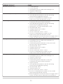
15
Black stain around any door 1. Too little primary air.
2. Too low a flue pull.
3. Downdraught in flue. Fit suitable anti-downdraught cowl.
4. Flue partly or fully blocked.
5. High fire screw set too high.
Burner carbons up after short period 1. Low fire screw set too low.
2. Oil Control filter blocked. Remove and clean with boiling
water and dry thoroughly before replacing.
3. Incorrect or contaminated fuel. Very little can cause
trouble. Clean out tank and refill with a new fuel.
Unable to light burner 1. Control metering stem slot obstructed. To clear, turn
Control Knob from OFF to full ON several times.
2. Oil Control filter blocked. Remove and clean with boiling
water and dry thoroughly before replacing.
3. Metering stem in oil control sticking. Replace control.
4. Fuel inlet blocked. Service.
5. Oil depth in burner base too shallow.
6. Oil level in tank too low.
7. Air lock in oil line tank – burner – control.
8. Incorrect or contaminated fuel. Very little can cause
trouble. Clean out tank and refill with a new fuel.
9. Electrical supply failed or turned off. Check power supply. If there is
a power cut, switch control to manual. See User’s Instructions.
Burner goes out after burning 1-2 hours 1. Too little primary air.
2. Downdraught in flue. Fit suitable anti-downdraught cowl.
3. Low fire screw set too low.
4. Control metering stem slot obstructed. To clear, turn Control
Knob from OFF to full ON several times.
5. Fuel inlet blocked. Service.
6. Oil depth in burner base too shallow.
7. Oil level in tank too low.
8. Air lock in oil line tank – burner – control.
9. Incorrect or contaminated fuel. Very little can cause
trouble. Clean out tank and refill with a new fuel.
Burner goes out for no apparent reason 1. Too little primary air.
2. Downdraught in flue. Fit suitable anti-downdraught cowl.
3. Flue partly or fully blocked.
4. Low fire screw set too low.
5. Control metering stem slot obstructed. To clear, turn
Control Knob from OFF to full ON several times.
6. Trip lever operated.
7. Oil Control filter blocked. Remove and clean with boiling
water and dry thoroughly before replacing.
8. Fuel inlet blocked. Service.
9. Oil level in tank too low.
10. Air lock in oil line tank – burner – control.
11. Incorrect or contaminated fuel. Very little can cause trouble.
Clean out tank and refill with a new fuel.
12. Electrical supply failed or turned off. Check power supply. If there is
a power cut, switch control to manual. See User’s Instructions.
EVIDENCE OF FAULT CAUSE
retention properties, and will lead to an overall loss of
efficiency, as well as condensation in flue and ovens.
•
vermiculite backfill, or the equivalent, is used whenever a
flexible liner is installed. It must be sealed top and bottom.
•
salt-glazed clay or pre-cast liners are acceptable.
•
the most appropriate cowl depends entirely on conditions at
the site. Several may have to be tried before one is found that
gives good all-year performance. In some circumstances it
may not be possible to entirely exclude downdraughts
caused by surrounding buildings or trees, so fit an anti-
downdraught cowl, preferably of the O-H type.
A ‘Chinaman’s Hat’ is not sufficient.
All electrical work must be carried out by competent persons.
This cooker requires an electrical supply 230V 50Hz. A 3Amp
fused spur is to be positioned within 90cm of the LH side of the
cooker, See diagram 14.
In addition, the supply can be wired in via an optional timer
control, see diagram 14.
This supply needs a transformer which connects to the oil valve
thermostat control fitted inside the cooker. Easy access is provided
via a magnetic access panel on the LH side of the cooker.
The cooker has a manual overide in the event of a power cut. See
User’s Instructions.
5. ELECTRICAL SUPPLY

3
INSTALLATION INSTRUCTIONS
The appliance is delivered fully assembled, with the exception of
the following items packed in a box in the Simmering Oven.
•
Set of Burner Shells
•
Astonish Cleaner
•
Burner Lid – 2 parts
•
Shelves (3)
•
Burner Ring
•
Cold Shelf
•
Vapour Chamber Lid
•
Roasting Dish (Lge)
•
Flue Collar & Filler Plate
•
Roasting Dish (Smll)
•
KBB Fire Valve
•
Cookbook
•
Set of Wicks
•
Instructions
To ensure optimum performance from this range cooker, it
must be installed and commissioned by a REDFYRE/OFTEC
approved engineer.
Installation must be carried out to accepted standards, and
comply with all regional and national regulations. Redfyre
Cookers will accept no responsibility or liability for any faults
arising from poor or incorrect installation.
Any alteration not approved by Redfyre Cookers could
invalidate the approval of the appliance and the operation of
its warranty, as well as adversely affecting the purchaser’s
statutory rights.
It is recommended that a qualified OFTEC engineer should
carry out servicing once, or preferably twice, a year.
It is a requirement under OFTEC regulations that the
installation is recorded on a CD 10 form (a copy is attached at
the end of this book). Once completed, a copy is to be given to
the end user and one copy sent to Gazco Ltd. Failure to do so
may invalidate the guarantee.
Installation must comply with these regulations:
The Building Regulations: Part J England and Wales; Part F,
Section III Scotland; Part L Northern Ireland; Part J Eire.
BS5440 Parts 1 & 2 installation of Flues and Ventilation.
BS5410 Part 1.
D.M.2. Installation in Timber Frame Buildings.
All OFTEC Codes of Practice.
Where a Standard or a Code of Practice is quoted, the current
version must be used.
1. IMPORTANT INFORMATION
3. DELIVERY
The location for the appliance must fit in with the layout and style
of the kitchen, and have:
access to services (oil and electricity);
enough space for the appliance, allowing access for
installation and maintenance;
a satisfactory flue;
a solid non-combustible hearth capable of supporting the
weight of the appliance.
4. LOCATION
2. COMPLIANCE
WARNING
CONTROL OF SUBSTANCES HARMFUL TO HEALTH
It is the responsibility of the user and installer to ensure that protective clothing is worn when materials known to be injurious to
health and safety are being handled.
•
Avoid inhalation when working with insulation materials such as ceramic board, glass fibre or mineral wool.
•
Use disposable protection for the eyes, skin and throat.
•
Use disposable gloves when handling fuels, fire cement and firebricks.
ALWAYS ENSURE THAT WORKING AREAS ARE WELL VENTILATED DURING INSTALLATION AND COMMISSIONING.
16
Burner soots up 1. Too little primary air.
2. Too low a flue pull.
3. Downdraught in flue. Fit suitable anti-downdraught cowl.
4. Vapourising Chamber lid not fully seated.
5. Shells not correctly seated.
6. Incorrect or contaminated fuel. Very little can cause
trouble. Clean out tank and refill with a new fuel.
COOKERS
Not reaching required temperature 1. Too little primary air.
2. To high a flue pull.
3. Flue partly or fully blocked.
4. High fire screw set too low.
Overheating 1. Too low a flue pull.
2. Low fire screw set too high.
Variations in temperature 1. Variations in flue draught. Fit suitable stabiliser.
EVIDENCE OF FAULT CAUSE
You need to allow at least a 3 mm gap between the
kitchen surfaces, cupboards or walls for expansion and
services.
4

For further advice or information please contact
your local AGA Specialist
With AGA’s policy of continuous product
improvement, the Company reserves the right to
change specifications and make modifications to
the appliance described at any time.
Manufactured by
AGA
Station Road
Ketley Telford
Shropshire TF1 5AQ
England
www.aga-web.co.uk
www.agacookshop.co.uk
www.agalinks.com
-
 1
1
-
 2
2
-
 3
3
-
 4
4
-
 5
5
-
 6
6
-
 7
7
-
 8
8
-
 9
9
-
 10
10
-
 11
11
-
 12
12
-
 13
13
-
 14
14
-
 15
15
-
 16
16
-
 17
17


Redfyre Classic Range Oil Cooker Owner's manual
- Category
- Cookers
- Type
- Owner's manual
- This manual is also suitable for
Ask a question and I''ll find the answer in the document
Finding information in a document is now easier with AI
Related papers
-
AGA Traditional Oil cooker Owner's manual
-
-
-
-
-
-
-
-
Other documents
-
Klean-Strip GKKH99991 Operating instructions
-
Aeg-Electrolux FM2500DD-A User manual
-
AEG FM2500DD-A User manual
-
-
-
-
Rayburn Cookmaster Plus 308K Installation & Servicing Instructions Manual
-
Sibir (N-SR) V170KE User manual
-
-
Cannon FLUERO-B User and Installation Guide