
SPLIT SYSTEM INDOOR COILS
ABOUT THE CONVERSION KIT
The horizontal conversion kit is designed to allow cased
coils to be mounted in the horizontal right or the horizontal
left position. The position is determined by airflow direction
when looking at the front of the unit as shown in Figure 1.
NOTE: Before converting the cased coil to a horizontal
configuration, determine if the installation is a horizontal left
or right application. The kit must be installed before the
refrigerant lines are connected.
INSTALLATION
1. Remove the coil access doors.
2. Slide the coil straight out the front of the unit.
3. Remove the knockouts from the front and rear delta
plates. See Figure 2.
NOTE: The coil has two sets of 1/4" knockouts; one set
in the front delta plate and one set in the rear delta plate.
The holes are used for holding the coil support rod in
either horizontal application (left or right). It is important
that only one hole from each set is opened. If the wrong
hole is opened, seal it with metal tape to prevent air
leakage. To determine which holes to open, locate your
installation type in Figure 1.
• For 18" conversion kits, continue to step 4.
• For 24" or 28" conversion kits, skip to step 6.
4. Prepare the horizontal drain pan for installation by cleaning
the 1" x 5/8" recessed areas (bottom of the pan)with the
alcohol wipe supplied in the kit.
5. Peel off the paper backing from the mounting tape on the
back of the clips and mount them in the cleaned recessed
areas of the drain pan. These clips will hold the support rod
in place once installed. NOTE: To determine which end
of the pan to mount the clips on, locate your installation
type in Figure 3 Install the clips with the open end facing
inwards as shown in Figure 3.
6. Install the coil support rod by inserting the ends of the
rod into the knocked out holes as shown in Figure 2.
NOTE: The coil support rod (with the tabs on the end)
goes in the holes that are in the front of the coil. Make
sure the rod ends clear the copper parts of the coil when
installed with the drain pan in step 7.
7. Attach the horizontal drain pan to the coil as shown in
Figure 2.
8. Install the plastic plug into the open hole of the vertical
drain pan to block bypass air flow. See Figure 2.
9. Place the insulation sheet (supplied with the kit) inside
the coil cabinet. Lay it on the surface the horizontal drain
pan will lay.
10. Place the coil and drain pan assembly back into the
cabinet as shown in Figure 1.
• For 18" conversion kits: Slip the bottom flange of the
drain pan extension under the coil support rod in the
drain pan. Make sure the side tabs fit inside the drain pan
on each side between the drain pan inside wall and the
coil support rod. See Figure 4. NOTE: Before installing
the drainpan extension, the flange that the support rod
rests on needs to be bent, creating a "C-Channel". This
will ensure the extension stays in place. To create the
"C-Channel", bend the flange upwards 90° (along the
perforation) as shown in Figure 4.
• For 24" or 28" conversion kits: The holes in the drain
pan extension should be pressed over the nibs molded
into the drain pan. To determine which pair of holes to
use depends on how the unit is installed horizontally
(left or right). Verify proper positioning for clearance
thru the top of the coil cabinet before affixing.
NOTE: The drain pan extension should extend into the
existing ductwork several inches. The drain pan extension
can be installed and removed after the ductwork has been
attached to the cased coil.
11. Reinstall the doors and secure with their screws.
HORIZONTAL CONVERSION KIT
INSTALLATION INSTRUCTIONS
IMPORTANT
It is your responsibility to know how to properly operate the equipment according to strict safety
guidelines and maintaining it for the life of the product. Safety should always be the deciding
factor when using this device and using common sense plays an important role as well. Pay
attention to all safety warnings and any other special notes highlighted in the manual.
These instructions are primarily intended to assist qualified individuals experienced in the
proper usage of this equipment. Please read all instructions carefully before using this device.
Improper usage of this equipment or failure to follow safety warnings could result in serious
injury, death, or property damage.
DO NOT DESTROY. PLEASE READ CAREFULLY & KEEP IN A SAFE PLACE FOR FUTURE REFERENCE.

708914B (Replaces 708914A)
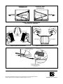
Figure 1. Horizontal Configurations
(with Drain Pan Extension)
HORIZONTAL LEFT
CONFIGURATION
HORIZONTAL RIGHT
CONFIGURATION
AIRFLOW
AIRFLOW
HORIZONTAL RIGHT
HORIZONTAL LEFT
PLUG
PLUG
KNOCKOUTS
(FRONT & REAR DELTA PLATES)
SUPPORT
ROD
SUPPORT
ROD
Figure 2. Drain Pan Installation
Figure 3. Support Rod Clip Locations
HORIZONTAL RIGHT
CLIP LOCATIONS
HORIZONTAL LEFT
CLIP LOCATIONS
DUCT
FLANGE
HORIZONTAL DRAIN PAN
(SHOWN W/CUTAWAY VIEW)
SUPPORT ROD
BEND THE FLANGE UPWARDS 90°
ALONG THE PERFORATION.
SLIP BOTTOM FLANGE UNDER
SUPPORT ROD
DRAIN PAN
EXTENSION
Figure 4. Drain Pan Extension
Specifications & illustrations subject to change without notice or incurring obligations (08/15).
O’Fallon, MO, © Nortek Global HVAC LLC 2015. All Rights Reserved.
-
 1
1
-
 2
2


Frigidaire C6B(A,H)-T Installation guide
- Type
- Installation guide
- This manual is also suitable for
Ask a question and I''ll find the answer in the document
Finding information in a document is now easier with AI
Related papers
-
Broan C7B(A,H)MX Installation guide
-
Broan C6 Horizontal Convertion Kit Installation guide
-
Broan Cased Coil Conversion Kit Installation guide
-
Broan C7B(A,H)M0 Installation guide
-
Broan Horizontal Left or Right Conversion Kit Installation guide
-
-
-
Broan MB7VM Installation guide
-
Broan C6B(A,H)-T Installation guide
-
Broan MB6(B,E,V)M Installation guide
Other documents
-
Unitary products group PDH Specification
-
Heat Controller HCH006 Operating instructions
-
Johnson Controls AV*(C) Series User manual
-
York SUNLINE K5EU090A50A User manual
-
-
Johnson Controls CP9C C Installation guide
-
-
Trane Performance Climate Changer PSCA Installation, Operation and Maintenance Manual
-
-