
Standard and Easy Mount
Cool Only: AJCS 06 LZA
AJCS 08, 10 AZA
Heat/Cool: AJES 06 LSA
AJES 08 ASA
AJES 10 DSA
Heat Pump: AJHS 08 ASA
49-7398 10-00 JR
www.GEAppliances.com
Owner’s Manual and
Installation Instructions
Room
Safety Information
Adapter Plugs . . . . . . . . . . . . . . . . . . 4
Connecting Electricity . . . . . . . . . . 3
Extension Cords . . . . . . . . . . . . . . . . 4
Safety Precautions . . . . . . . . . . . . . . 2
Operating Instructions
Air Direction . . . . . . . . . . . . . . . . . . . 6
Controls . . . . . . . . . . . . . . . . . . . . . 5, 6
Fan Switch . . . . . . . . . . . . . . . . . . . . . 6
Temperature Limiting . . . . . . . . . .6
Vent Control . . . . . . . . . . . . . . . . . . .6
Care and Cleaning
Air Filter . . . . . . . . . . . . . . . . . . . . . . . 8
Front Grille . . . . . . . . . . . . . . . . . . . . .7
Grille and Case . . . . . . . . . . . . . . . . . 7
Outdoor Coils . . . . . . . . . . . . . . . . . . 7
Installation
Installation for Models with
Accordion Curtains . . . . . . . . .17–21
Installation for Models with
Filler Panels . . . . . . . . . . . . . . . .10–16
Preparing to Install . . . . . . . . . . . . . 9
Through the Wall . . . . . . . . . . . . . 22
Troubleshooting Tips
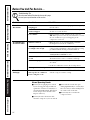
Before You Call For Service . . . . 26
Normal Operating Sounds . . . . . 26
Consumer Support
Consumer Support . . . . Back Cover
Warranty . . . . . . . . . . . . . . . . . . . . . 27
Write the model and serial numbers here:
# ________________________________
# ________________________________
Find these numbers on a label on the
front of the base pan behind the front grille.
Air Conditioners

2
IMPORTANT SAFETY INFORMATION.
READ ALL INSTRUCTIONS BEFORE USING.
WARNING!
For your safety, the information in this manual must be followed to minimize the risk of fire or
explosion, electric shock, or to prevent property damage, personal injury, or loss of life.
■ Use this appliance only for its intended
purpose as described in this Owner’s
Manual.
■ This air conditioner must be properly
installed in accordance with the
Installation Instructions before it is used.
■ Never unplug your air conditioner by
pulling on the power cord. Always grip
plug firmly and pull straight out from the
receptacle.
■ Repair or replace immediately all electric
service cords that have become frayed
or otherwise damaged. Do not use a cord
that shows cracks or abrasion damage
along its length or at either the plug or
connector end.
■ Turn the mode control to
OFF
and unplug
your air conditioner before making any
repairs or cleaning.
NOTE:
We strongly recommend that any
servicing be performed by a qualified
individual.
■ For your safety…do not store or use
combustible materials, gasoline or other
flammable vapors or liquids in the vicinity
of this or any other appliance.
SAFETY PRECAUTIONS
Consumer Support Troubleshooting Tips Installation Instructions Care and Cleaning Operating Instructions Safety Instructions

Safety Instructions Operating Instructions Care and Cleaning Installation Instructions Troubleshooting Tips Consumer Support
3
Do not, under any circumstances, cut or remove the third (ground) prong from the power cord.
For personal safety, this appliance must be properly grounded.
The power cord of this appliance is equipped
with a 3-prong (grounding) plug which mates
with a standard 3-prong (grounding) wall
outlet to minimize the possibility of electric
shock hazard from this appliance.
Have the wall outlet and circuit checked by a
qualified electrician to make sure the outlet is
properly grounded.
Where a 2-prong wall outlet is encountered,
it is your personal responsibility and
obligation to have it replaced with a properly
grounded 3-prong wall outlet.
The air conditioner should always be
plugged into its own individual electrical
outlet which has a voltage rating that matches
the rating plate.
This provides the best performance and also
prevents overloading house wiring circuits
which could cause a fire hazard from
overheated wires.
See the Installation Instructions,
Electrical
Requirements
section for specific electrical
connection requirements.
HOW TO CONNECT ELECTRICITY
www.GEAppliances.com

Consumer Support Troubleshooting Tips Installation Instructions Care and Cleaning Operating Instructions Safety Instructions
4
IMPORTANT SAFETY INFORMATION.
READ ALL INSTRUCTIONS BEFORE USING.
WARNING!
Because of potential safety hazards under
certain conditions, we strongly recommend
against the use of an extension cord.
However, if you must use an extension cord,
it is absolutely necessary that it be a UL-listed,
14 gauge, 3-wire grounding type appliance
extension cord having a grounding type plug
and outlet and that the electrical rating of the
cord be 15 amperes (minimum) and 125 volts.
CAUTION:
DO NOT use an extension cord with any of
the 230/208 volt models.
USE OF EXTENSION CORDS –
115-Volt models only
Because of potential safety hazards under
certain conditions, we strongly recommend
against the use of an adapter plug.
However, if you must use an adapter, where
local codes permit, a
temporary connection
may be made to a properly grounded 2-prong
wall outlet by use of a UL-listed adapter
available at most local hardware stores.
The larger slot in the adapter must be aligned
with the larger slot in the wall outlet to
provide proper polarity in the connection
of the power cord.
When disconnecting the power cord from
the adapter, always hold the adapter in place
with one hand while pulling the power cord
plug with the other hand. If this is not done,
the adapter ground terminal is very likely to
break with repeated use.
If the adapter ground terminal breaks,
DO
NOT USE
the air conditioner until a proper
ground has been established.
Attaching the adapter ground terminal to a wall
outlet cover screw does not ground the appliance
unless the cover screw is metal, and not insulated,
and the wall outlet is grounded through the house
wiring. You should have the circuit checked by a
qualified electrician to make sure the outlet is
properly grounded.
USE OF ADAPTER PLUGS –
115-Volt models only
READ AND FOLLOW THIS SAFETY INFORMATION CAREFULLY.
SAVE THESE INSTRUCTIONS

Safety Instructions Operating Instructions Care and Cleaning Installation Instructions Troubleshooting Tips Consumer Support
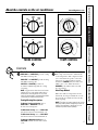
Controls
Mode Control
HIGH COOL
and
LOW COOL
provide cooling
with different fan speeds.
HIGH HEAT
and
LOW HEAT
provide heating
with different fan speeds.
LOW FAN
or
HIGH FAN
provides air
circulation and filtering without cooling
or heating.
NOTE: If you move the switch from a cool or heat
setting to OFF or to a fan setting, wait at least 3
minutes before switching back to a cool or heat
setting. A 3-minute delay is automatically provided
on the Heat/Cool and Heat Pump models.
Cooling/Heating Descriptions
For Normal Cooling or Heating
—Select
HIGH COOL
or
HIGH HEAT
with the
thermostat at mid point.
For Maximum Cooling
—Select
HIGH COOL
with the thermostat at maximum cool.
For Maximum Heating
—Select
HIGH HEAT
with the thermostat at maximum heat.
For Quieter & Nighttime Cooling
—Select
LOW COOL
with the thermostat at mid
point.
Temp Control
The temp control is used to maintain the
room temperature. The compressor will
cycle on and off to keep the room at the
same level of comfort. When you turn
the knob to
COOLER
(blue) the indoor air
will become cooler. Turn the knob to
WARMER
(red) and the indoor air will
become warmer.
Heat Pump Models
When the outdoor temperature is lower
than 25°F., heat is provided by the electric
heater in the air conditioner instead of by
the heat pump.
NOTE: The electric resistance heater in the 115-volt
heat pump model operates during defrost when the
outdoor coil temperature is below 36°F. It is not
intended to provide full heat capability.
MODE CONTROL TEMP CONTROL
OFF
LOW
FAN
HIGH
FAN
HIGH
HEAT
HIGH
COOL
LOW
COOL
LOW
HEAT
W
A
R
M
E
R
C
O
O
L
E
R
OFF
LOW
FAN
HIGH
FAN
HIGH
COOL
LOW
COOL
C
O
O
L
E
R
About the controls on the air conditioner.
www.GEAppliances.com
5

Consumer Support Troubleshooting Tips Installation Instructions Care and Cleaning Operating Instructions Safety Instructions
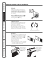
6
Temperature Limiting
Limiting the maximum and minimum settings
prevents users from turning the control to the
extreme heat or cool positions.
The normal range of the temp control is
approximately 60°F to 85°F. The control range
may be narrowed by the use of the temperature
limiting screws located behind the control panel.
Each position equals approximately 3°F.
Vent Control
The vent control is located behind the front grille
on the right side of the air discharge area. When
set at
CLOSE,
only the air inside the room will be
circulated and conditioned. When set at
OPEN,
some inside air is exhausted outside.
To open or close the vent:
1. Remove the front grille.
2. Remove and replace the vent card to the OPEN
(mesh end toward the back) or to the CLOSE
(mesh end toward the front) position.
Air Direction
Horizontal louvers
on the front grille
let you control the
air direction up
and down.
Remove the front
grille to adjust the
vertical louvers
side-to-side to
direct the air left
or right.
Fan Switch
On Heat/Cool models, the fan switch lever is
located in a hole through the control panel. To
reach it, you need to remove the front grille. Use
a small screwdriver to change the setting. Cool
only models have a rocker switch on the front of
the control box.
When set at
CYCLE
(down) the fan cycles on and
off when cooling or heating. When set at
CONT
(continuous, up) the fan runs all the time. The
unit is shipped in the
CONT
setting.
About the controls on the air conditioner.
Limits
heat
temp
Limits
cool
temp
Open
Close

7
Care and cleaning of the air conditioner.
www.GEAppliances.com
Safety Instructions Operating Instructions Care and Cleaning Installation Instructions Troubleshooting Tips Consumer Support
Outdoor Coils
The coils on the outdoor side of the air
conditioner should be checked regularly.
If they are clogged with dirt or soot they may be
professionally steam cleaned, a service available
through your GE service outlet.
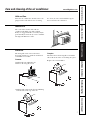
Grille and Case
Turn the air conditioner off and remove the
plug from the wall outlet before cleaning.
To clean, use water and a mild detergent.
Do not use bleach or abrasives.
The front grille can be removed for more
thorough cleaning or to make the model and
serial numbers accessible.
To remove:
1. Pull the filter up and slide it out.
2. Remove the two grille screws.
3. Pull the grille out from the bottom and lift up
from the tabs on the top of the case.
To replace:
Hook the tabs on the front grille even with the
tabs on the front of the case and snap into place.
Replace the screws and filter.
Front Grille
Grille
Tab
Grille
Tab

Consumer Support Troubleshooting Tips Installation Instructions Care and Cleaning Operating Instructions Safety Instructions
8
Care and cleaning of the air conditioner.
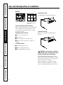
To maintain optimum performance, clean the filter at least every 30 days.
Air Filter
Turn the air conditioner off before cleaning.
The most important thing you can do to maintain
the air conditioner is to clean the filter at least
every 30 days. A clogged filter reduces cooling,
heating and air flow.
Keeping the air filter clean will:
■Decrease cost of operation.
■Save energy.
■Prevent clogged heat exchanger coils.
■Reduce the risk of premature component
failure.
To clean the air filters:
■Vacuum off the heavy soil.
■Run water through the filters.
■Dry thoroughly before replacing.
To remove the air filter:
Carefully pull the tab forward, up and out.
To replace the air filter:
Replace the clean filter by pushing it back
into place.
CAUTION: Do not operate the air conditioner
without the filter in place. If a filter becomes torn or
damaged it should be replaced immediately.
Operating without the filter in place or with a
damaged filter will allow dirt and dust to reach
the indoor coil and reduce the cooling, heating,
airflow and efficiency of the unit.
Replacement filters are available from your
salesperson, GE dealer, GE Service and Parts
Center or authorized Customer Care® servicers.
Dirty filter—Needs cleaning Clogged filter—Greatly
reduces cooling, heating
and airflow.
FRONT
FRONT

Safety Instructions Operating Instructions Care and Cleaning Installation Instructions Troubleshooting Tips Consumer Support
9
Preparing to install the air conditioner.
Read these instructions completely and carefully.
NOTE TO INSTALLER: Leave these instructions
with the air conditioner after installation is
completed.
NOTE TO CONSUMER: Keep this Owner’s
Manual and Installation Instructions for future
use.
IMPORTANT NOTES:
For personal safety, this air conditioner must be
properly grounded.
It is important to have the wall outlet and circuit
checked by a qualified electrician if there is any
doubt as to whether a proper ground exists.
Follow National Electric Codes (NEC) and/or
local codes and ordinances.
CAUTION:
Do not, under any circumstances, cut or remove
the third (ground) prong from the power cord.
Do not change the plug on the power cord of this
air conditioner.
Aluminum house wiring may present special
problems—consult a qualified electrician.
Before You Begin
Some models require 115/120-volt a.c.,
60 Hz grounded outlet protected with
a 15-amp time delay fuse or circuit
breaker.
The 3-prong grounding plug minimizes the
possibility of electric shock hazard. If the wall
outlet you plan to use is only a 2-prong outlet, it is
your responsibility to have it replaced with a
properly grounded 3-prong wall outlet.
Some models require 230/208-volt
a.c., protected with a time delay fuse
or circuit breaker. These models
should be installed on their own single
branch circuit for best performance
and to prevent overloading house
or apartment wiring circuits, which
could cause a possible fire hazard
from overheating wires.
Electrical Requirements
■ Phillips-head screwdriver
■ Ruler or tape measure
■ Scissors or knife
■ Pencil
■ Level
■ Wood saw
■ Adjustable wrench
■ Drill
Tools You Will Need

Consumer Support Troubleshooting Tips Installation Instructions Care and Cleaning Operating Instructions Safety Instructions
10
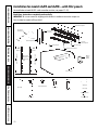
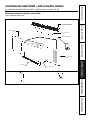
Installation for models AJES and AJHS—with filler panels.
(for installation of model AJCS—with accordion curtains, see pages 17–21)
Read these instructions completely and carefully.
IMPORTANT: Be sure to remove the shipping pad inside the air conditioner next to the compressor.
Parts included for models AJES and AJHS.
Air conditioner
Type C (painted) (6)
Type D (2)
Type E (4)
Large washer (2)
Adjusting bolt (2)
Lock nut (2)
Spacer (2)
Support bracket hardware
Type A (9)
Type B (2)
Sill support
bracket (2)
2 angles
(left and right hand)
Case side
gasket (2)
Spring clip (4)
Window
locking
bracket
Vinyl window gasket
Bottom window gasket
Filler Panels
Cut panels and
discard center
piece
Case top gasket
Foam top
window gasket
B
Right side
A
Left side
(holes are on the left)
(holes are on the right)

Safety Instructions Operating Instructions Care and Cleaning Installation Instructions Troubleshooting Tips Consumer Support
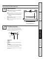
Read completely, then follow step-by-step.
Window Requirements
■These instructions are for a standard double-
hung window. You will need to modify them
for other types of windows.
■The air conditioner can be installed without the
accordion panels if needed to fit in a narrow
window. See the window opening dimensions
to the right.
■All supporting parts must be secured to firm
wood, masonry or metal.
■The electrical outlet must be within reach of
the power cord.
Window opening dimensions are for a
standard double-hung window.
17″min.
31″to 43″
(With filler panels)
26
1
⁄4″ min.
(Without filler panels)
Storm Window Requirements
A storm window frame will not allow the air
conditioner to tilt towards the outside and will
keep it from draining properly. To adjust for this,
attach a piece of wood to the stool.
WOOD PIECES:
WIDTH:
2″
LENGTH:
Long enough to fit inside the window
frame.
THICKNESS:
To determine the thickness, place a
piece of wood on the stool to make it 1/2″higher
than the top of the storm window frame.
Attach securely with nails or screws provided by
the installer.
1/2″higher
than frame
Storm
window
frame
Wood
Stool
Sill
1
2
11

Consumer Support Troubleshooting Tips Installation Instructions Care and Cleaning Operating Instructions Safety Instructions
12
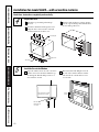
Installation for models AJES and AJHS—with filler panels.
Read these instructions completely and carefully.
Remove the Air Conditioner From the Case.
Remove the front grille. See the
Care and
Cleaning
section.
Find the locking plate located on the front
left side.
Remove the screw and the locking plate to
unlock the air conditioner.
Remove and discard the shipping screw on
the back of the air conditioner to allow
removal of the air conditioner from the case.
Pull the bottom corners of the air
conditioner and slide it out of the case.
Remove the shipping pad inside the air
conditioner next to the compressor.
Remove the rear grille that is taped to the
back of the case. Remove the packet of screws
taped to the back of the grille. While holding
the grille at a 45° angle, insert it into the clips
at the top of the case and push the bottom in.
Keep slight upward pressure on the grille
until it fits flush with the bottom of the case.
If attaching the grille from the outside of the
case use the 2 long screws.
If attaching the grille on the inside of the case use
the 2 short screws.
G
REMOVE SHIP PAD!
REMOVE TAPE ON
VENT LEVER!
F
E
D
C
B
A
3
Locking
plate
Remove
screw
Remove
screw
Remove
shipping pad
Clips
Insert the 2 long screws on the outside
Insert the 2 short screws on the inside

Safety Instructions Operating Instructions Care and Cleaning Installation Instructions Troubleshooting Tips Consumer Support
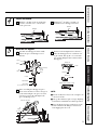
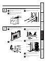
Prepare the Window
Mark the centerline of the stool. Measure
from the centerline 13
3
⁄8″ on both sides
for the panel cuts.
Measure 12
3
⁄8″from the centerline on
both sides for the sill support brackets.
BA
4
Install the Sill Supports
Assemble the sill supports. Do not fully
tighten the spacer mounting screws at
this time.
Before attaching the sill supports, place
them on the window stool. Select the spacer
position that will place the spacer near the
outermost point on the sill. Tighten the
spacer mounting screws.
Turn the bolts and tighten the lock nuts to
make the sill supports level or tilt down 1/8″
to the outside. Line up the “V” notch with
12
3
⁄8″marks. Drill pilot holes and attach the
sill supports.
NOTES:
■On narrow sills, there may not be enough room
to use the lock nut.
■A deep offset sill may require a longer adjusting
bolt than the standard hex head bolt provided.
■On wood sills use the large washer between the
bolt head and the sill. This prevents the bolt
from digging into the wood.
C
B
A
5
13
Stool
Sill
12
3
⁄8″
13
3
⁄8″
Centerline
Centerline
Spacer
Type B
Type E
Spacer mounting
screws
Type (A)
Lock nut
Sill
support
Adjusting bolt
Large washer
(For use with wood sills)
Sill support
Average sill
Narrow sill
Offset sill (such as brick or stone)
Bolt
Sill
Stool
Sill
support
“V” notch
Screws are in position
Spacer

Consumer Support Troubleshooting Tips Installation Instructions Care and Cleaning Operating Instructions Safety Instructions
14
Installation for models AJES and AJHS—with filler panels.
Read these instructions completely and carefully.
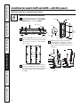
Measure, Cut and Install the Filler Panels
Measure from the edge of the panel marks
(see Prepare the Window)
to the
inside of the
window track
on each side.
(A and B)
Mark the
A
and
B
measurements on each
side of the filler panel board. Cut the panels
and discard the center piece. Note position
of the notches.
Put together the panel assemblies. Remove
the paper backing from the case side gasket
and attach it to the angle. Push a pencil point
through the gaskets to locate the holes in
the angles.
Install the panels in the window. Place
the spring clips 3″from the top and the
bottom. Squeeze and push the clips to fit
in the window track and the tab into the
sill support.
D
C
B
A
6
Sill
A
Window track
Width of the air conditioner
(panel marks)
Left side
B
Right side
13
3
⁄8″ 13
3
⁄8″
Filler Panels
Cut panels
and discard
center piece
B
Right side
A
Left side
(holes are on the left)
(holes are on the right)
Gasket
Gasket
Angle
Panel
Tab
Type C
(painted
screws)
Angle
Hook the tab into the
sill support
3″

Safety Instructions Operating Instructions Care and Cleaning Installation Instructions Troubleshooting Tips Consumer Support
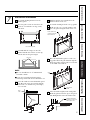
Install the Case in the Window
Peel off the backing from the bottom
window gasket.
Place the gasket on the stool and over the
brackets, even with the rear edge, sticky
side down.
Carefully slide the empty case into the
window until the holes in the case line up
with the holes in the panel angles.
NOTES:
■The case should have a 1/8″minimum tilt
toward the outside.
■Be sure the seal gasket and panel gaskets
remain in position and do not roll with the case.
Lower the window so it fits behind the panel
tabs. Insert the 4 type A screws through the
holes in the case and into the panel angles,
2 on each side.
With the window closed, mark where the
window sash meets the case.
Peel off the backing from the case top gasket.
Hold on to the case, open the window, and
place the gasket along the mark on the case.
Place the vinyl window gasket over the case
top gasket. Insert the panel tabs through the
slits in the gasket. Cut the gasket on each side
to the width of the window.
Close the window tightly on the vinyl gasket.
Bend the gasket forward to expose the panel
tabs. Drill pilot holes into the window sash.
I
H
G
F
E
D
C
B
A
7
15
Bottom window gasket
Case holes
Panel
tabs
Case
screws
Put the gasket on top
of the case where the
window will close.
Panel
tab
Vinyl window
gasket
Attach the panel tab to
the window on each side
with a type D screw.

Consumer Support Troubleshooting Tips Installation Instructions Care and Cleaning Operating Instructions Safety Instructions
16
Installation for models AJES and AJHS—with filler panels.
Read these instructions completely and carefully.
Install the Window Gasket and the Locking Bracket
Cut the foam top window gasket to the
window width.
Stuff the foam between the glass and the
window to prevent air and insects from
getting into the room.
Attach the window locking bracket with 1
type E screw.
C
B
A
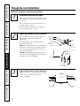
8
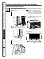
Replace the Air Conditioner in the Case
Carefully slide the air conditioner back into
the case.
Attach the power cord to the base pan with
the clamp.
When the wall outlet is to the left, extend the
cord under the unit and hold it in place with
the clamp.
Reinstall the locking plate with the tab behind
the wall case flange. Tighten the screw.
Reattach the front grille. An opening for the
power cord is on the bottom of the front
grille.
Fill holes and cracks with caulking provided
by the installer.
F
E
D
C
B
A
9
Clamp
Power cord
Power cord
Clamp
Locking
plate
Tighten
screw
Base pan

Safety Instructions Operating Instructions Care and Cleaning Installation Instructions Troubleshooting Tips Consumer Support
Installation for model AJCS—with accordion curtains.
(for installation of models AJES and AJHS—with filler panels, see pages 10–16)
Read these instructions completely and carefully.
Parts included for model AJCS.
17
Air conditioner
Type A (6)
Type B (15)
Foam top window gasket
Accordion curtain
(left)
Sill channel
Foam top window gasket
Window locking bracket
Top mounting rail
Accordion curtain
(right)

Consumer Support Troubleshooting Tips Installation Instructions Care and Cleaning Operating Instructions Safety Instructions
18
Window Requirements
■These instructions are for a standard double-
hung window. You will need to modify them
for other types of windows.
■The air conditioner can be installed without the
accordion panels if needed to fit in a narrow
window. See the window opening dimensions
to the right.
■All supporting parts must be secured to firm
wood, masonry or metal.
■The electrical outlet must be within reach of
the power cord.
Window opening dimensions are for a
standard double-hung window.
17″min.
29″to 49″
(With accordion curtains)
26
1
⁄4″ min.
(Without accordion curtains)
Storm Window Requirements
A storm window frame will not allow the air
conditioner to tilt towards the outside and will
keep it from draining properly. To adjust for this,
attach a piece of wood to the stool.
WOOD PIECES:
WIDTH:
2″
LENGTH:
Long enough to fit inside the window
frame.
THICKNESS:
To determine the thickness, place a
piece of wood on the stool to make it 1/2″higher
than the top of the storm window frame.
Attach securely with nails or screws provided by
the installer.
1/2″higher
than frame
Storm
window
frame
Wood
Stool
Sill
1
2
Installation for model AJCS—with accordion curtains.
Read completely, then follow step-by-step.

Safety Instructions Operating Instructions Care and Cleaning Installation Instructions Troubleshooting Tips Consumer Support
19
Remove the Air Conditioner From the Case.
Remove the front grille. See the
Care and
Cleaning
section.
Find the locking plate located on the front
left side.
Remove the screw and the locking plate to
unlock the air conditioner.
Remove and discard the shipping screw on
the back of the air conditioner to allow
removal of the air conditioner from the case.
Pull the bottom corners of the air
conditioner and slide it out of the case.
Remove the rear grille that is taped to the
back of the case. Remove the packet of screws
taped to the back of the grille. While holding
the grille at a 45° angle, insert it into the clips
at the top of the case and push the bottom in.
Keep slight upward pressure on the grille
until it fits flush with the bottom of the case.
If attaching the grille from the outside of the
case use the 2 long screws.
If attaching the grille on the inside of the case use
the 2 short screws.
F
E
D
C
B
A
3
Locking
plate
Remove
screw
Remove
screw
Clips
Insert the 2 long screws on the outside
Insert the 2 short screws on the inside

Consumer Support Troubleshooting Tips Installation Instructions Care and Cleaning Operating Instructions Safety Instructions
20
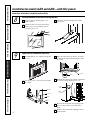
Prepare the Case
Install the top mounting rail with type
B screws.
Attach the sill channel with type B screws.
Align the holes on the bracket of the sill
channel with the holes in the case.
Slide the right and left accordion curtains
into the top mounting rail and sill channel.
Secure with type B screws.
C
B
A
Install the Case in the Window
Open the window and center the case in the
window. Lower the window behind the top
mounting rail. This should provide a 1/8″
tilt toward the outside.
Extend curtains and drill pilot holes in
the side of the window and the window
sash. Attach the curtains with 3 screws
on each side.
BA
4
5
Installation for model AJCS—with accordion curtains.
Read these instructions completely and carefully.
Align holes
Mounting rail
Sill channel
Place the sill
channel into the
stool offset.
Case should have a slight
tilt down to the outside.
Type A
screws
Page is loading ...
Page is loading ...
Page is loading ...
Page is loading ...
Page is loading ...
Page is loading ...
Page is loading ...
Page is loading ...
-
 1
1
-
 2
2
-
 3
3
-
 4
4
-
 5
5
-
 6
6
-
 7
7
-
 8
8
-
 9
9
-
 10
10
-
 11
11
-
 12
12
-
 13
13
-
 14
14
-
 15
15
-
 16
16
-
 17
17
-
 18
18
-
 19
19
-
 20
20
-
 21
21
-
 22
22
-
 23
23
-
 24
24
-
 25
25
-
 26
26
-
 27
27
-
 28
28


Ask a question and I''ll find the answer in the document
Finding information in a document is now easier with AI
Related papers
Other documents
-
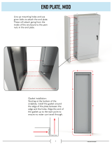 SCE SCE-MOD72EPT Installation Information
-
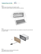 SMI Ventilation Products VWM614 Installation guide
-
Unbranded PF5773AC User guide
-
AmeriHome 801132 User manual
-
 SPEEDI-GRILLE SG-212 FLB User guide
-
Whirlpool R1012 Installation Instructions And Use & Care Manual
-
Samsung AW0529 User manual
-
-
-
Signature Hardware 398659 Installation guide


