Page is loading ...

FREESTANDING OUTDOOR GRILL
Installation Instructions and Use & Care Guide
For questions about features, operation/performance, parts, accessories or service, call: 1-877-373-2301
or visit our website at www.Kitchenaidgrills.com
ASADORE AUTÓNOMO PARA EXTERIORES
Instrucciones de instalación y Manual de uso y cuidado
Para consultas respecto a características, funcionamiento, rendimiento, piezas, accesorios o servicio técnico, llame al: 1-877-373-2301
o visite nuestro sitio de internet en www.Kitchenaidgrills.com
GRIL D'EXTÉRIEUR AUTOPORTANT
Pour des questions à propos des caractéristiques, du fonctionnement/rendement, des pièces, des accessoires ou du service,
composer le : 1-877-373-2301
ou visitez notre site web www.Kitchenaidgrills.com
Table of Contents/Índice/Ta ble des matières ..................................................................2
720-0732 (LP) 730-0732 (NG)

2
TABLE OF CONTENTS
OUTDOOR GRILL SAFETY............................................................3
INSTALLATION REQUIREMENTS ................................................5
Tools and Parts ............................................................................5
Location Requirements................................................................5
Product Dimensions ....................................................................6
Electrical Requirements ...............................................................6
Gas Supply Requirements ...........................................................7
Gas Connection Requirements....................................................7
REPLACEMENT PARTS ................................................................9
INSTALLATION INSTRUCTIONS ................................................13
Freestanding Outdoor Grill Installation
......................................13
Make Gas Connection ...............................................................16
GAS CONVERSIONS....................................................................18
Tools and Parts for Gas Conversion..........................................18
Conversion from LP Gas to Natural Gas ...................................18
Check and Adjust the Burners...................................................22
OUTDOOR GRILL USE ................................................................23
Using Your Outdoor Grill............................................................23
Hood Lights................................................................................24
Using Your Searing Side Burner ................................................25
Using Your Rotisserie Burner.....................................................25
Rotisserie Cooking Tips .............................................................26
TIPS FOR OUTDOOR GRILLING
................................................27
Cooking Methods.......................................................................27
Grilling Chart...............................................................................28
OUTDOOR GRILL CARE..............................................................30
Replacing the Igniter Battery......................................................30
Changing the Light Bulb.............................................................30
General Cleaning........................................................................31
TROUBLESHOOTING ..................................................................32
ASSISTANCE ................................................................................33
Accessories ................................................................................33
WARRANTY ..................................................................................34
ÍNDICE
SEGURIDAD DEL ASADOR PARA EXTERIORES .....................36
REQUISITOS DE INSTALACIÓN.................................................38
Herramientas y piezas................................................................38
Requisitos de ubicación.............................................................38
Medidas del producto................................................................39
Requisitos eléctricos..................................................................39
Requisitos del suministro de gas...............................................40
Requisitos para la conexión de gas...........................................41
PIEZAS DE REPUESTO ...............................................................42
INSTRUCCIONES DE INSTALACIÓN.........................................46
Instalación del asador autónomo para exteriores .....................46
Conexión del suministro de gas ................................................49
CONVERSIONES DE GAS ...........................................................51
Herramientas y piezas para la
conversión de gas......................................................................51
Conversión de gas LP a gas natural..........................................51
Revise y regule los quemadores................................................55
USO DEL ASADOR PARA EXTERIORES ...................................56
Cómo usar el asador para exteriores.........................................57
Luces de la capota.....................................................................58
Cómo usar el quemador lateral para dorado rápido.................58
Cómo usar el quemador del rostizador .....................................60
Consejos para la cocción con el rostizador...
............................60
CONSEJOS PARA ASAR AL AIRE LIBRE..................................61
Métodos de cocción ..................................................................62
Cuadro para asar........................................................................62
CUIDADO DEL ASADOR PARA EXTERIORES..........................66
Cómo reemplazar la batería del encendedor ............................66
Cómo cambiar el foco................................................................66
Limpieza general ........................................................................67
SOLUCIÓN DE PROBLEMAS......................................................69
ASISTENCIA..................................................................................69
Accesorios..................................................................................69
SÉCURITÉ DU GRIL D'EXTÉRIEUR ...........................................72
GARANTÍA.....................................................................................70
TABLE DES MATIÈRES
EXIGENCES D’INSTALLATION...................................................74
Outils et pièces...........................................................................74
Exigences d'emplacement.........................................................74
Dimensions du produit...............................................................75
Spécifications électriques..........................................................75
Spécifications de l'alimentation en gaz .....................................76
Exigences concernant le raccordement au gaz........................77
INSTRUCTIONS D’INSTALLATION ............................................82
Installation du gril d’extérieur a
utoportant.................................82
Raccordement au gaz................................................................85
CONVERSIONS POUR CHANGEMENT DE GAZ ......................88
Outils et pièces pour conversion de gaz ...................................88
Conversion de propane à gaz naturel........................................88
Contrôle et réglage des brûleurs ...............................................92
UTILISATION DU GRIL D’EXTÉRIEUR.......................................93
Utilisation du gril d’extérieur.......................................................93
Lampes sous le couvercle..........................................................95
Utilisation du brûleur à rôtissage latéral.....................................95
Utilisation du brûleur de tournebroche ......................................96
Conseils de cuisson à l’aide du tournebroche ..........................97
CONSEILS POUR L'UTILISATION DU GRIL D'EXTÉRIEUR ....98
Méthodes de cuisson.................................................................98
Tableau de cuisson au gril .........................................................99
ENTRETIEN DU GRIL D’EXTÉRIEUR .......................................102
Remplacement de la pile de l’allumeur....................................102
Changement de l’ampoule d’éclairage
....................................102
Nettoyage général ....................................................................103
DÉPANNAGE...............................................................................105
ASSISTANCE ..............................................................................105
Accessoires ..............................................................................105
GARANTIE...................................................................................106
PIÈCES DE RECHANGE ..............................................................7

3
OUTDOOR GRILL SAFETY
You can be killed or seriously injured if you don't immediately
You
can be killed or seriously injured if you don't
follow
All safety messages will tell you what the potential hazard is, tell you how to reduce the chance of injury, and tell you what can
happen if the instructions are not followed.
Your safety and the safety of others are very important.
We have provided many important safety messages in this manual and on your appliance. Always read and obey all safety
messages.
This is the safety alert symbol.
This symbol alerts you to potential hazards that can kill or hurt you and others.
All safety messages will follow the safety alert symbol and either the word “DANGER” or “WARNING.”
These words mean:
follow instructions.
instructions.
DANGER
WARNING
If you smell gas:
1. Shut off gas to the appliance.
2. Extinguish any open flame.
3. Open lid.
4. If odor continues, keep away from the
appliance and immediately call your
gas supplier or your fire department.
DANGER
WARNING
1. Do not store or use gasoline or other
flammable liquids or vapors in the
vicinity of this or any other appliance.
2. An LP cylinder not connected for use
shall not be stored in the vicinity of
this or any other appliance.
State of California Proposition 65 Warnings:
WARNING: This product contains one or more chemicals known to the State of California to cause cancer.
WARNING: This product contains one or more chemicals known to the State of California to cause birth defects or other
reproductive harm.
In the State of Massachusetts, the following installation instructions apply:
■
Installations and repairs must be performed by a qualified or licensed contractor, plumber, or gasfitter qualified or licensed by
the State of Massachusetts.
■
If using a ball valve, it shall be a T-handle type.
■
A flexible gas connector, when used, must not exceed 3 feet.
IMPORTANT: This grill is manufactured for outdoor use only. For grills that are to be used at elevations above 2000 ft (609.6 m) orifice
conversion is required. See “Gas Supply Requirements” section. It is the responsibility of the installer to comply with the minimum
installation clearances specified on the model/serial rating plate. The model/serial rating plate for freestanding models can be found on
the left-hand inside cabinet wall.

SAVE THESE INSTRUCTIONS
IMPORTANT SAFETY INSTRUCTIONS
WARNING: To reduce the risk of fire, electrical shock,
injury to persons, or damage when using the outdoor cooking
gas appliance, follow basic precautions, including the
following:
■ Do not install portable or built-in outdoor cooking gas
appliances in or on a recreational vehicle, portable trailer,
boat or in any other moving installation.
■ Always maintain minimum clearances from combustible
construction, see “Location Requirements” section.
■ The outdoor cooking gas appliance shall not be located
under overhead unprotected combustible construction.
■ This outdoor cooking gas appliance shall be used only
outdoors and shall not be used in a building, garage, or any
other enclosed area.
■ Keep any electrical supply cord and fuel supply hose away
from any heated surfaces.
■ Keep outdoor cooking gas appliance area clear and free
from combustible materials, gasoline and other flammable
vapors and liquids.
■ Do not obstruct the flow of combustion and ventilation air.
Keep the ventilation openings of the cylinder enclosure free
and clear from debris.
■ Open the cabinet door and inspect the gas cylinder supply
hose before each use of the outdoor cooking gas
appliance. If the hose shows excessive abrasion or wear,
or is cut, it MUST be replaced before using the outdoor
cooking gas appliance. Contact your dealer and use only
replacement hoses specified for use with the outdoor
cooking gas appliance.
■ Visually check the burner flames.
They should be blue. Slight
yellow tipping is normal for LP
gas. The flames should be
approximately 1" (2.5 cm) high.
■ Check and clean burner/venturi tube for insects and insect
nest. A clogged tube can lead to fire under the outdoor
cooking gas appliance.
■ The LP gas supply cylinder to be used must be:
- constructed and marked in accordance with the
Specification for LP Gas Cylinders of the U.S. Department
of Transportation (DOT) or the National Standard of
Canada, CAN/CSA-B339, Cylinders, Spheres, and Tubes
for Transportation of Dangerous Goods; and Commission.
- provided with a listed overfilling prevention device.
- provided with a cylinder connection device compatible
with the connection for outdoor cooking gas appliances.
■ Always check connections for leaks each time you connect
and disconnect the LP gas supply cylinder. See
“Installation Instructions” section.
■ When the outdoor cooking gas appliance is not in use, the
gas must be turned off at the supply cylinder.
■ Storage of an outdoor cooking gas appliance indoors is
permissible only if the cylinder is disconnected and
removed from the outdoor cooking gas appliance.
■ Cylinders must be stored outdoors and out of the reach of
children and must not be stored in a building, garage, or
any other enclosed area.
■ The pressure regulator and hose assembly supplied with
the outdoor cooking gas appliance must be used. A
replacement pressure regulator and hose assembly
specific to your model is available from your outdoor
cooking gas appliance dealer.
■ Gas cylinder must include a collar to protect the cylinder
valve.
■ For appliances designed to use a CGA791 Connection:
Place a dust cap on cylinder valve outlet whenever the
cylinder is not in use. Only install the type of dust cap on
the cylinder valve outlet that is provided with the cylinder
valve. Other types of caps or plugs may result in leakage
of propane.
If the following information is not followed exactly, a fire
causing death or serious injury may occur.
■ Do not store a spare LP gas cylinder under or near this
outdoor cooking gas appliance.
■ Never fill the cylinder beyond 80 percent full.
1"
(2.5 cm)
4

5
INSTALLATION REQUIREMENTS
Tools and Parts
Gather the required tools and parts before starting installation.
Read and follow the instructions provided with any tools listed
here.
Tools Needed
■ Phillips screwdriver
■ Wrench or pliers
■ Pipe wrench
■ Scissors or cutting pliers
(to remove tiedowns)
■ Noncorrosive leak-
detection solution
Parts Supplied
■ Gas pressure regulator/hose assembly set for 11" WCP LP
gas
■ Right side shelf with sear burner
■ Left side shelf
■ Searing side burner control knob
■ “AA” Batteries (1)
■ Warming rack
■ Cooking grid
■ Side burner cooking grid
■ Natural gas orifice for rotisserie/infrared burner
Parts Needed
■ 20 lb LP gas fuel tank - approximately 18" (45.7 cm) height
Parts Needed for Conversion to Natural Gas
■ Natural gas conversion kit Part Number 710-0003. See
“Assistance” section to order. The conversion kit includes:
■ Natural gas regulator 4" W.C. (marked “Natural Gas
Regulator”)
■ 10 ft (3.0 m) Natural gas hose with quick connector
■ 5.9" (150 mm) Natural gas regulator hose
■ 6 mm nut driver
■ 6 mm wrench
■ Hex key
■ Gas line shutoff valve
■ ½" male pipe thread nipple for connection to pressure
regulator.
■ LP gas-resistant pipe-joint compound
■ CSA design-certified outdoor flexible stainless steel appliance
connector (4-5 ft [1.2-1.5 m]) or rigid gas supply line as
needed.
Location Requirements
WARNING
Explosion Hazard
Do not store fuel tank in a garage or indoors.
Do not store grill with fuel tank in a garage or indoors.
Failure to follow these instructions can result in death,
explosion, or fire.
WARNING
Fire Hazard
Do not use grill near combustible materials.
Do not store combustible materials near grill.
Doing so can result in death or fire.
Select a location that provides minimum exposure to wind and
traffic paths. The location should be away from strong draft areas.
Do not obstruct flow of combustion and ventilation air.
Clearance to combustible construction for freestanding outdoor
g
rills:
■ A minimum of 24" (61 cm) must be maintained between the
front of the grill hood, sides and back of the grill and any
combustible construction.
■ A 24" (61 cm) minimum clearance must also be maintained
below the cooking surface, and the grill shall not be used
under overhead combustible construction.
Rotisserie (accessory)*
If you equip your grill with a rotisserie, a 6" (15.2 cm) minimum
clearance is needed for the rotisserie motor.
A grounded, 3-prong outlet located to the left of
the grill is
required.
*See “Assistance” section to order.

6
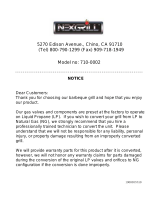
Product Dimensions
Electrical Requirements
If codes permit and a separate ground wire is used, it is
recommended that a qualified electrician determine that the
ground path is adequate.
Check with a qualified electrician if you are not sure whether the
grill is properly grounded.
A 120-volt, 60-Hz, AC-only, 15-amp, fused electrical supply is
required.
It is recommended that a separate circuit servicing only this grill
be provided.
To avoid electrical shock, do not immerse cord or plugs in
water or other liquid.
Unplug from the outlet when not in use and before cleaning.
Allow to cool before putting on or taking off parts.
Do not operate any outdoor cooking gas appliance with a
damaged cord, damaged plug, or after the appliance
malfunctions or has been damaged in any manner. Contact
the manufacturer for repair.
Do not let the cord hang over the edge of a table or touch hot
surfaces.
Do not use an outdoor cooking appliance for purposes other
than intended.
When connecting, first connect plug to the outdoor cooking
gas appliance then plug appliance into the outlet.
Use only a Ground Fault Interrupter (GFI) protected circuit
with this outdoor cooking gas appliance.
Do not remove the ground prong or use with an adapter of
2prongs.
Use only extension cords with a 3 prong grounding plug rated
for the power of the equipment and approved for outdoor use
with a W-A marking.
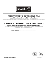
The model/serial number rating plate is located on the inside of
the left cabinet door. See the following illustration.
Recommended Ground Method
The outdoor grill, when installed, must be electrically grounded in
accordance with local codes or, in the absence of local codes,
with the National Electrical Code ANSI/NFPA 70, or Canadian
Electrical Code, CSA C22.1.
Copies of the standards listed above may be obtained from:
CSA International
8501 East Pleasant Valley Rd.
Cleveland, Ohio 44131-5575
National Fire Protection Association
One Batterymarch Park
Quincy, Massachusetts 02269
12
5/8
"
(32 cm)
52
3/8
"
(133.0 cm)
28" (71.1 cm)
12
5/8
"
(32 cm)
48
5/8
"
(123.5 cm)
23"
(58.4 cm)
Electrical Shock Hazard
Use only a UL listed, 14 gauge, 3 wire extension cord
approved for outdoor use, marked W-A, with a
maximum length of 50 ft.
Plug into a grounded 3 prong outlet.
Do not remove ground prong.
Do not use an adapter.
Failure to follow these instructions can result in death,
re, or electrical shock.
WARNING
A. Model/serial number plate
A. 3-prong ground plug
B. 3-prong polarized type outdoor GFI outlet
C. Ground prong
A
A
B
C

7
Gas Supply Requirements
WARNING
Explosion Hazard
Use a new CSA International approved “outdoor”
gas supply line.
Securely tighten all gas connections.
If connected to LP, have a qualified person make sure
gas pressure does not exceed 11” (28 cm) water
column.
Examples of a qualified person include:
licensed heating personnel,
authorized gas company personnel, and
authorized service personnel.
Failure to do so can result in death, explosion, or fire.
Observe all governing codes and ordinances.
IMPORTANT: This installation must conform with all local codes
and ordinances. In the absence of local codes, installation must
conform with either the National Fuel Gas Code, ASNI Z223.1/
NFPA 54, Natural Gas and Propane Installation Code, CSA
B149.1, Propane Storage and Handling Code, B149.2, or the
Standard for Recreational Vehicles, ASNI A119.2/NFPA 1192 and
CSA Z240 RV Series Recreational Vehicle Code as applicable.
IMPORTANT: Grill must be
connected to a regulated gas supply.
Refer to the model/serial rating plate for information on the type of
gas that can be used. If this
information does not agree with the
type of gas available, check with your local gas supplier.
Gas Conversion:
No attempt shall be made to convert the grill from the gas
specified on the model/ser
ial rating plate for use with a different
gas type without consulting the serving gas supplier. The
conversion kit supplied with grill must be used. See “Gas
Conversions” section for instructions.
Gas Pressure Regulator
The gas pressure regulator supplied with this grill must be used.
The inlet (supply) pressure to the regulator should be as follows
for proper operation:
LP Gas:
Operating pressure: 11" (27.9 cm) WCP
Inlet (supply) pressure: 11" to 14" (27.9 cm to 35.5 cm) WCP
Natural Gas:
Operating pressure: 4" (10.2 cm) WCP
Inlet (supply) pressure: 7" to 14" (17.8 cm to 35.5 cm) WCP
maximum.
Contact local gas supplier if you are not sure about the inlet
(suppl
y) pressu
re.
Burner Requirements for High Altitude
Input ratings shown on the model/serial rating plate are for
elevations up to 2,000 ft (609.6 m).
For elevations above 2,000 ft (609.6 m), ratings are reduced at a
rate
of 4% for each 1,000 ft (304.8 m) above sea level. Orifice
conversion is required. See “Assistance” section to order.
Gas Supply Line Pressure Testing
Testing above ½ psi (3.5 kPa) or 14" (35.5 cm) WCP (gauge):
The grill and its individual shutoff valve must be disconnected
from the gas supply piping system
during any pressure testing of
that system at test pressures greater than ½ psi (3.5 kPa).
Testing below ½ psi (3.5 kPa) or 14" (35.5 cm) WCP (gauge) or
lower:
The g
rill must be isolated from the gas supply piping system by
closing its individ
ual manual shutoff valve during any pressure
testing of the gas supply piping system at test pressures equal to
or less than ½ psi (3.5 kPa).
Gas Connection Requirements
20 lb LP Gas Fuel Tank
This grill is equipped for use with a 20 lb LP gas fuel tank (fuel
tank not supplied). A gas pressure regulator/hose assembly is
supplied.
Any brand of 20 lb LP gas fuel tank is acceptable for use with the
grill, pro
vided that it is compatible with the grill’s retention means
(tank tray included).
It is also design-certified by CSA International for local LP gas
supply or fo
r Natural gas with appropriate conversion.
A
A. Gas pressure regulator/hose assembly
The 20 lb LP gas fuel tank must be mounted and secured.
Door Style Tank Tray
1. Open cabi
net doors.
2. Slide th
e tank tray locking bracket counterclockwise 90° and
pull out the
tray.
A
A. Tank tray locking bracket

8
3. Place the 20 lb LP gas fuel tank bottom collar into the
mounting hole in the tank tray.
4. Ti
ghten the locking screw against the bottom collar of the
20 lb LP ga
s fuel tank to secure.
A
C
B
A. Locking screw
B. Bottom collar
C. Mounting hole
5. Slide the drawer with the 20 lb LP gas fuel tank back into the
cabinet. Turn the tank tray locking bracket clockwise 90° to
tighten.
A
A. Tank tray locking bracket
Natural Gas Conversion
Conversion must be made by a qualified gas technician. The
qualified Natural gas technician shall provide the Natural gas
supply to the selected grill location in accordance with the
National Fuel Gas Code ANSI Z223.1/NFPA 54 - latest edition,
and local codes. For conversion to Natural gas, the Natural Gas
Conversion Kit supplied with the grill (on some models) or the
Natural Gas Conversion Kit Part Number 710-0003 must be used.
See “Assistance” section for information on ordering.
IMPORTANT: The
gas installation must conform with local codes,
or in the absence of local codes, with the National Fuel Gas Code,
ANSI Z223.1/NFPA 54 - latest edition.
Follow instructions for converting to Natural gas in the “Gas
Con
versions” section of this
manual or the instructions supplied
with Natural Gas Conversion Kit Part Number 710-0003.
The gas supply line shall be equipped with an approved shutoff
v
alve
. This valve should be located in the same area as the grill
and should be in a location that allows ease of opening and
closing. Do not block access to the shutoff valve. The valve is for
turning on or shutting off gas to the grill.
A
B
C
A. Gas supply line
B. Shutoff valve “open” position
C. To grill

10
Part
Number
Part (description) Warranty
Coverage
Quantity
01 0732-001
Main lid
3 1
02 0732-002
Main lid screw
3 2
03 0732-003
Temperature gauge
housing
1 1
04 0732-00
4
Temperature gauge
1 1
05 0732-005
Logo
1 1
06 0732-006
Main lid handle seat, left
1 1
07 0732-007
Main lid handle seat, right
1 1
08 0732-008
Main lid handle tube
1 1
09 0732-009
Rear baffle
1 1
10 0732-010
Rotisserie burner ignition
wire
1 1
11 0732-011
Rotisserie heat shield
1 1
12 0732-012
Rotisserie burner
1 1
13 0732-013
Rotisserie burner igniter
brac
ke
t
1 2
14 0732-014
Rotisserie burner flex gas
line
1 1
15 0732-015
Rotisserie burner with
brass elbow
1 1
16 073
2-016
Main lid bracket, left
1 1
17 0732-017
Main lid bracket, right
1 1
18 0732-018
Front baffle
1 1
19 0732-019
Regulator, LP
1 1
20 0732-020
Sear gas valve
3 1
21 0732-021
Side manifold
1 1
22 0732-022
Side burner flex gas line
1 1
23 0732-023
Rotisserie gas valve
3 1
24 0732-024
Main manifold
1 1
25 0732-025
Igniter junction wire
1 1
26 0732-068
Main gas valve
3 4
27 0732-027
Control panel light
1 1
28 0732-028
Main control panel
3 1
29 0732-029
Light switch
1 1
30 0732-030
Tempered glass fix panel
1 1
31 0732-031
Tempered glass
1 1
32 0732-032
Control knob
1 5
33 0732-033
Control knob bezel
1 5
34 0732-034
Control knob bezel,
rotisser
ie b
urner
1 1
35 0732-035
Control knob, rotisserie
bu
rner
1 1
36 0732-036
Cart frame, front
1 1
37 0732-037
Door magnet
1 2
38 0732-038
Side shelf, left
3 1
39 0732-039
Side shelf front panel, left
3 1
Part
Number
Pa
rt (description) Warranty
Coverage
Quantity

11
40 Rubber grommet 1 3
41 0732-041
Side panel, left
3 1
42 0732-042
Door hinge bracket
1 4
43 0732-043
Swivel caster with brake
1 1
44 0732-044
Swivel caster
1 1
45 0732-045
Caster
1 2
46 0732-046
Bottom panel
1 1
47 0732-047
Tank tray
1 1
48 0732-048
Gas tank tray slide
brack
et, left
1 1
49 0732-049
Gas tank tray slide
bracket, right
1 1
50 0732-050
Gas tank tray slide
1 2
51 0732-051
Tank tray bolt
1 1
52 0732-052
Gas tank tray block piece
1 1
53 0732-053
Grease box
1 1
54 0732-054
Door hinge
1 4
55 0732-055
Door handle seat
1 4
56 0732-056
Door handle tube
1 2
57 0732-057
Door, left
3 1
58 0732-058
Door, right
3 1
59 0732-059
Lighting rod
1 1
60 0732-060
Lighting rod cover
1 1
61 0732-061
Electric igniter module
1 1
62 0732-062
Side panel, right
3 1
63 0732-063
Cable strainer securing
pla
te
1 1
Pa
rt
Num
ber
P
art (description) Warranty
Coverage
Quantity
64 0732-064
Cable strainer
1 1
65 0732-065
Back panel
3 1
66 0732-066
Igniter wire cover
1 1
67 0732-067
Side burner control panel,
ri
ght
3 1
68 0732-068
Side burner bowl
assembly
1 1
69 0732-06
9
Side burner grease tray
1 1
70 0732-070
Sear burner
1 1
71 0732-071
Sear burner igniter wire
1 1
72 0732-072
Sear burner cooking grid
wi
th hole
3 1
73 07
32-073
Side burner lid
3 1
74 0732-074
Side burner lid hinge rod
1 2
75 0732-075
Transformer
1 1
76 0732-076
Lamp cord
1 1
77 0732-077
Lamp
1 2
78 0732-078
Lamp case
1 1
79 0732-079
Main burner igniter wire A
1 1
Part
Numbe
r
Pa
rt (description) Warranty
Coverage
Quantity

12
80 0732-080
Main burner igniter wire B
1 1
81 0732-081
Main burner igniter wire C
1 1
82 0732-082
Main burner igniter wire D
1 1
83 0732-083
Main burner
5 4
84 0732-084Flame tamer 3 4
Part
Num
ber
P
art (description) Warranty
Coverage
Quantity
85 0732-085
Cooking grid with hole
3 3
86 0732-086Warming rack 3 1
87 0732-087
Burner pin assembly
1 4
Items not shown
88 0732-088
Natural gas orifice
pack
age
89 0732-089
Manual
Part
Numbe
r
Part (description) Warranty
Coverage
Quantity

13
INSTALLATION INSTRUCTIONS
Freestanding Outdoor Grill Installation
Excessive Weight Hazard
Use two or more people to move and install grill.
WARNING
Failure to do so can result in back or other injury.
Unpack Grill
1. Remove all packaging materials and remove grill from the
shipping base.
2. Move grill close to desired outdoor location.
3. Open the grill hood.
Remove Packaging Material Inside the Grill
1. Use a utility knife to cut straps and packing tape to open box
from top and remove the boxes.
2. Remove the warming shelf and grill grates from inside the grill
and remov
e the package inside the firebox.
3. Remove foam block and wrap from inside the grill.
Attach Right Side Shelf with Sear Burner
1. Unpack right side shelf with sear burner.
2. Open grill lid.
3. Remove 3 screws from the side of the searing side burner.
A
A. Searing side burner screws
4. Remove the 3 screws on the grill side panel and 1 screw on
the grill control panel.
A
B
A. Grill control panel screw
B. Grill side panel screws
5. Lower the side shelf so that the center post (A) slides into the
bracket (B) and align the bottom keyhole slots on the side
shelf with the screw holes on the grill side panel.
B
A
IMPORTANT: This step is meant to help with the installation,
but do not depend solely on the bracket to hold the weight of
the sear burner.
6. Attach the top of the side shelf to the grill (A) by inserting the
3 screws remo
ved in Step 3 into the side shelf from inside the
grill
hood and tighten. See illustration in Step 8.
7. Attach the bottom of the side shelf to the side panel (B and C)
of the
grill by inserting the 3 screws removed from the grill
side panel in Step 4. Tighten the screws. See illustration in
Step 8.

14
8. Attach the side shelf to the control panel (D) by inserting the
screw removed from the grill control panel in Step 4. Tighten
the screw.
9. Remove the 3 screws from the searing side burner.
10. Remove the searing side burrner.
11. Remove the 2 screws from the side burner valve assembly.
See illustration in Step 13.
12. Push the valve stem out through the opening in the front of
the side burner shelf, lining up the holes in the side burner
valve assembly with the openings on the side burner shelf.
See illustration in Step 13.
13. Slide the bezel opening over the valve stem and attach the
side burner valve assembly and bezel to the side burner shelf
with the screws removed in Step 11.
14. Replace the searing side burner, angling it so that the side
burner tube slides over the valve orifice. Locked 3 screws
removed in step 9.
15. Connect electrical plugs on underside of sear burner.
A. Bezel
B. Valve stem
A. Electrical plug from grill
B. Electrical plug from sear burner
A
B
A
B
A
B
C
D
16.Insert the valve stem into the knob and push knob into place.
17.The igniter battery is not factory installed. A “AA” size alkaline
battery is located in the manual bag. Install battery at this
time following the instructions in “Replacing the Igniter
Battery” section.

15
Attach Left Side Shelf
1. Unpack left side shelf.
2. Open grill lid.
3. Remove 3 screws from the side of the side shelf.
4. Remove the screw from the central post, then 2 screws on
the grill side panel and 1 screw on the grill control panel.
5. Lower the side shelf so that the side shelf center post (A)
slides into the bracket (B) and align the bottom keyhole slots
on the side shelf with the screw holes on the grill side panel.
IMPORTANT: This step is meant to help with the installation, but
do not depend solely on the bracket to hold the weight of the
side shelf.
6. Attach the top of the side shelf to the grill (B) by inserting the
3 screws removed in Step 3 into the side shelf from inside the
grill hood and tighten. See illustration in Step 8.
7. Attach the bottom of the side shelf to the side panel (A and D)
of the grill by inserting the 3 screws removed from the grill
side panel in Step 4. The drip pan may need to be pulled
forward to install the center screw (D). Tighten the screws.
See illustration in Step 8.
8. Attach the side shelf to the control panel (C) by inserting the
screw removed from the grill control panel in Step 4. Tighten
the screw.
A. Side shelf screws
A. Grill side panel screws
B. Grill control panel screw
B
A
C
D
A
B
A
B
A
Complete Assembly
1. Replace the grill grates.
2. Place warming shelf on brackets as shown..
A. Warming shelf brackets
B. Warming shelf
B
A

16
Make Gas Connection
NOTE: If grill is to be converted to Natural gas, follow instructions
in the “Gas Conversions” section.
20 lb LP Gas Fuel Tank
WARNING
Explosion Hazard
Securely tighten all gas connections.
If connected to LP, have a qualified person make sure
gas pressure does not exceed 11” (28 cm) water
column.
Examples of a qualified person include:
licensed heating personnel,
authorized gas company personnel, and
authorized service personnel.
Failure to do so can result in death, explosion, or fire.
LP Gas:
IMPORTANT: A 20 lb LP gas fuel tank must be purchased
separately.
IMPORTANT:
The gas pres
sure regulator/hose assembly
supplied with the grill must be used. Replacement gas pressure
regulator/hose assembly specific to your model, is available from
your outdoor grill dealer.
Door Style Tank Tray
1. Open cabinet doors.
2. Slide the tank tray locking bracket counterclockwise 90° and
pull out the tray.
A
A. Tank tray locking bracket
3. Place the 20 lb LP gas fuel tank bottom collar into the
mounting hole in the tank tray.
4. Tighten the locking screw against the bottom collar of the
20 lb LP
gas fuel tank to secure.
A
C
B
A. Locking screw
B. Bottom collar
C. Mounting hole
5. Slide the tank tray with the 20 lb LP gas fuel tank back into the
cabinet and lock the locking bracket.
To Connect the 20 lb LP Gas Fuel Tank:
1. Check that the 20 lb LP gas fuel tank is in the “Off” position. If
not, turn the valve clockwise until it stops.
2. Check that the 20 lb LP gas fuel tank valv
e has the proper
type-1 external male thread connections per ANSI Z21.81.
3. Check that the burner control knobs are in the “Off” position.
4. Remove any debris and inspect the valve connections, port,
and g
as pressure regulator/hose assembly for damage.
NOTE: Always keep the LP cylinder at 90° (upright)
orientation
to provide vapor withdrawal.
5. Using your hand, turn the gas pressure regulator/hose
assembly clockwise to connect to the 20 lb LP gas fuel tank as
shown.
Hand tighten only. Use of a wrench could damage the quick
coupling nu
t.
A
B
A. Gas pressure regulator/hose assembly
B. 20 lb LP gas fuel tank
Make sure that the cylinder valve connection device properly
mates with the connection device attached to the inlet of the
pressure regulator.
6. Open the tank valve
fully by turning the valve
counterclockwise. Wait a few minutes for gas to move through
the gas line.
7. Before lighting the grill, test all connections by brushing on an
approv
ed noncorrosive leak-detection solution. Bubbles will
show a leak.
8. If a leak is found, turn the tank valve off and do not use the
grill
. Contact a qualified gas technician to make repairs.
9. Go
to “Check and Adjust the Burners” section.

17
To Disconnect the 20 lb LP Gas Fuel Tank:
1. Check that the burner control knobs are in the “Off” position
and the grill is cool.
2. Che
ck that the 20 lb LP gas fuel tank is in the “Off” position. If
not, turn
the valve clockwise until it stops.
3. Using your hand, turn the gas pressure regulator/hose
assembly counte
rclockwise to disconnect to the 20 lb LP gas
fuel tank as shown.
Hand loosen only. Use of a wrench could damage the quick
coup
ling nu
t.
A
A. Gas pressure regulator/hose assembly
B. 20 lb LP gas fuel tank
4. Place dust cap on cylinder valve outlet whenever the cylinder
is not in use. Only install the type of dust cap on the cylinder
valve outlet that is provided with the cylinder valve. Other
types of caps or plugs may result in leakage of propane.
5. Go to “Plug in Grill” in this section.
Plug in Grill
Electrical Shock Hazard
Use only a UL listed, 14 gauge, 3 wire extension cord
approved for outdoor use, marked W-A, with a
maximum length of 50 ft.
Plug into a grounded 3 prong outlet.
Do not remove ground prong.
Do not use an adapter.
Failure to follow these instructions can result in death,
fire, or electrical shock.
WARNING
1. Plug extension cord into grounded 3-prong GFI outlet.
A
B
C
A. 3-prong ground plug
B. 3-prong polarized type outdoor GFI outlet
C. Ground prong
2.
■ To avoid electrical shock, do not immerse cord or plugs in
water or other liquid.
■ Unplug from the outlet when not in use and before
cleaning. Allow to cool before putting on or taking off parts.
■ Do not operate any outdoor cooking gas appliance with a
damaged cord, damaged plug, or after the appliance
malfunctions or has been damaged in any manner.
Contact the manufacturer for repair.
■ Do not let the cord hang over the edge of a table or touch
hot surfaces.
■ Do not use an outdoor cooking appliance for purposes
other than intended.
■ When connecting, first connect plug to the outdoor
cooking gas appliance then plug appliance into the outlet.
■ Use only a Ground Fault Interrupter (GFI) protected circuit
with this outdoor cooking gas appliance.
■ Do not remove the ground prong or use with an adapter of
2 prongs.
■ Use only extension cords with a 3 prong grounding plug
rated for the power of the equipment and approved for
outdoor use with a W-A marking.
3. Go to “Check and Adjust the Burners” section.

18
GAS CONVERSIONS
Tools and Parts for Gas Conversion
Gather the required tools and parts before starting installation.
Read and follow the instructions provided with any tools listed
here.
Tools needed
■ Phillips screwdriver
■ Pipe wrench
■ Adjustable wrench
■ 6 mm socket and wrench
or 6 mm nut driver
■ Thin flat-blade screwdriver
■ Pliers
■ Pipe thread sealant
certified for LP gas
Parts supplied
■ Natural gas orifices
Parts needed
■ Natural gas conversion kit Part Number 710-0003. See
“Assistance” section to order. The conversion kit includes:
■ Natural gas regulator 4" W.C. (marked “Natural Gas
Regulator”)
■ 10 ft (3.0 m) Natural gas hose with quick connector
■ 5.9" (150 mm) Natural gas regulator hose
■ 6 mm nut driver
■ 6 mm wrench
■ Hex key
IMPORTANT: Gas conv
ersions must be done by a qualified
installer. Before proceeding with conversion, shut off the gas
supply to the appliance prior to disconnecting the electrical power.
WARNING
Explosion Hazard
Use a new CSA International approved “outdoor”
gas supply line.
Securely tighten all gas connections.
Failure to do so can result in death, explosion, or fire.
Conversion from LP Gas to Natural Gas
Installation of the regulator
1. Turn off the main gas supply valve.
2. Unplug grill or disconnect power.
3. Disconnect 20 lb LP gas fuel tank (if present).
4. Turn off all burner control valves.
5. Remove the 20 lb LP gas fuel tank (if present) from the grill
car
t.
6. Use an
adju
stable wrench to remove the LP regulator from the
manifo
ld.
7. Use an adjustable wrench to install the Natural gas regulator
hose to the manifold and secure. Attach the Natural gas
regulator to the side panel inside the grill cart with the two
screws that are preassembled on the regulator.
Make Gas Connection
1. A combination of pipe fittings must be used to connect the grill
to the existing gas line.
■ The 10 ft (3.0 m) PVC flexible gas supply hose design-
certified by CSA must be used.
■ Pipe-joint compounds suitable for use with Natural gas
must be used. Do not use Teflon
®†
†®TEFLON is a registered trademark of E.I. Du Pont De Nemours and Company.
tape.
■ There must be a certified manual shutoff valve in the gas
supply line near the grill for easy access.
2. Connect the brass connector on one end of the 10 ft (3.0 m)
PVC flex
ible gas supply hose to the Natural gas pressure
regulator.

19
3. Connect the quick connector on the other end of the
10 ft (3.0 m) PVC flexible gas supply hose to the rigid Natural
gas supply pipe.
Change Grill Burner Valve Orifices
1. Remove the grates and flame tamers.
2. Remove the screw and cotter clip that hold the burner in
place. Set the screw and clip aside. Remove the burner from
the grill by lifting the burner out.
3. Use a 6 mm socket and wrench or 6 mm nut driver to remove
the brass orifice from the end of gas valve. The main burner
orifice is located behind the LP orifice, so no additional orifice
needs to be installed.
IMPORTANT: Check that the orifice is properly installed
inside of the burner opening.
4. Reinsert the burner and reattach using the 1 screw and cotter
clip previously removed. Repeat the procedure for each main
burner.
5. Position the igniters so they are ¼" (6.0 mm) away from each
burner.
Change the Rotisserie/Infrared Burner Orifice
1. Using a Phillips screwdriver, unscrew the 2 screws and
remove the rotisserie/infrared burner wind baffle.
A. Left side panel
B. Manifold
C. 10 ft (3.0m) PVC gas hose
D. Natural gas pressure regulator/hose assembly
B
A
C
D
A. Main burner orifice
A
A
2 screws
Wind Baffle

20
2. Using a Phillips screwdriver, remove the 6 screws at the back
of grill from inside the grill.
3. Remove the access cover at the back of the grill hood by
removing the 6 screws.
4. Using a Phillips screwdriver, remove the 1 screw holding the
spider guard to the burner.
5. Use 24 mm wrench to remove the orifice nut.
6. Take out the orifice support, and then use a 6 mm socket and
wrench or 6 mm nut driver to remove the LP orifice at the end
of the supply pipe. Replace with Natural gas orifice.
IMPORTANT: Check that the orifice is properly installed inside
of the supply pipe.
7. Reinstall the spider guard, access cover, and wind baffle.
Change the Sear Burner Orifices
1. Remove the screw securing the igniter and the 2searing side
burner screws.
A. Access cover
A
A. Orifice nut
A

21
2. Lift out the searing side burner.
3. Locate the Liquid propane orifice at the end of the valve.
A
A. Orifice
4. Use 6 mm socket wrench or 6 mm nut driver to remove the
orifice. Replace with the Natural gas orifice.
A
A. Orifice
IMPORTANT: Check that the orifice is properly installed inside
of the valve.
5. Reinstall the searing side burner. Make sure that the igniter is
out of the way to allow proper positioning of burner. Use
Phillips screwdriver to attach the mounting screws.
6. Use Phillips screwdri
ver to reattach the igniter and searing
side burner plate.
7. Reinstall searing side burner cover. Use Phillips screwdriver to
attach mounting
screws.
8. Open the manual shu
toff valve in the gas supply line. The
valve is open when the handle is parallel to the gas pipe.
A
B
A. Closed valve
B. Open valve
9. Test all connections using an approved noncorrosive leak-
detection solution. Bubbles will show a leak. Correct any leak
found.
Record Conversion
1. The appliance nameplate is located inside the grill cabinet on
the left-hand cabinet side. With a permanent marker, check
the box next to “Natural gas” and mark through “LP -
Propane.”
In the last page of the Use and Care Guide, write “Converted to
Natural Gas.” Also record the conversion date and the technician/
company that performed the conversion.
NOTE: Place LP gas parts in plastic par
ts bag for future use and
keep with pack containing literature.
Adjust High Flame Setting Screw
When converting from LP to Natural gas, you will need to adjust
the high flame setting screw for ideal burner flame height.
1. Pull
out each control knob for the main burner and side burner.
2. Use a flat-blade screwdriver to turn the high flame setscrew
counterclockwise approximate 90°.
3. Check that burner operates at the new high flame setting. It
may be necessary to adjust the screw setting slightly more to
get the ideal burner flame height.
/