Page is loading ...

ECR International Inc
2201 Dwyer Avenue
Utica, NY 13501
e-mail: info@RetroAire.com
e Right Fit for Comfort
P/N 240009719, Rev. C [08/31/2012]
An ISO 9001-2008 Certied Company
™
CM / CW / WM
R-410A High Efciency Water Source Heat Pump
MODEL CM - Heat Pump Nominal Capacities
8,000 12,000 15,000 Btuh
2.3 3.5 4.4 kW
MODEL CW - Straight Cooling / Heat Pump
Nominal Capacities
8,000 10,000 13,000 17,000 Btuh
2.3 2.9 3.8 5.0 kW
MODEL WM - Heat Pump Nominal
Capacities
9,000 12,000 15,000 Btuh
2.6 3.5 4.4 kW
Installation, Operation,
& Maintenance Manual
CM
Replacement for:
Freidrich and Climate Master
"801" Series Water Source
CW
New Construction
Replacement for:
Freidrich and Climate Master
CW and "800" Series Water
Source
WM
Replacement for:
McQuay, Singer, or Climate
Control WM Series Water
Source

Information and specications outlined in this manual in effect at the
time of printing of this manual. ECR International reserves the right to
discontinue, change specications or system design at any time without
notice and without incurring any obligation, whatsoever.
TABLE OF CONTENTS
Table Of Contents ........................................................................................................... 2
Receiving Information ..................................................................................................... 3
Important Safety Information ........................................................................................... 4
Dimensional/Physical Data ............................................................................................... 5
Product Description ......................................................................................................... 9
General Product Information .......................................................................................... 11
Installation Preparation ................................................................................................. 12
Installation .................................................................................................................. 13
Final Inspection And Start-Up ......................................................................................... 14
Sequence Of Operation.................................................................................................. 17
Maintenance ............................................................................................................... 19
Performance Data CM / CW / WM ** ............................................................................... 21
Electrical Specications ................................................................................................. 22
The Right Fit for Comfort 2 Made in USA

Inspection
Check shipment against bill of lading.
Verify equipment received as ordered.
Verify unit:
• Unit size and type correct per submittal sheet and
job requirements?
• Voltage correct?
• Correct Chassis has been received (with options as
ordered)?
• Electric heat correct capacity, if used?
• Hydronic coil included, if required? Piping located
as required?
Inspect each component for damage. Concealed
damage must be reported to carrier within 15 days
of receipt of shipment.
Carrier must make proper notation on delivery
receipt of all damage identied and complete carrier
inspection report.
Purchaser must notify Manufacturer’s Service
department of all damage and is responsible for ling
any necessary claims with carrier.
Customer Service : (800) 228-9364
Shipping damage MUST be reported to the carrier IMMEDIATELY.
Examine exterior.
Remove cover and examine compressor and piping for signs of damage.
RECEIVING INFORMATION
General Information
Installation shall be completed by qualied agency.
Retain
this manual and warranty for future reference.
Installer review this manual to verify unit has been
installed correctly. Run unit for one complete cycle to
verify proper function.
To obtain technical service or warranty assistance
during or after installation, contact your local
representative.
Visit our web site www.retroaire.com for local
representative listing.
For further assistance call 1-800-325-5479.
When calling for assistance, please have following
information ready:
Model Number_________________________
Serial Number_________________________
Date of installation______________________
The Right Fit for Comfort 3 Made in USA

Safety Information
• Use this unit for its for intended use only.
• Installation by qualied personnel.
• Turn off electrical supply before servicing unit.
• Inspect all parts for damage prior to installation and
start-up.
• Do not use unit if it has damaged wiring, is not working
properly, or has been damaged or dropped.
• Connect to properly grounded electrical supply with
proper voltage as stated on rating plate.
• Have proper over-current protection (i.e. time- delay
fuse/HACR Breaker) as listed on Rating Plate.
• Connect unit to properly grounded electrical supply. Do
not fail to properly ground this unit.
• Tampering voids all warranties.
IMPORTANT SAFETY INFORMATION
Become Familiar With Symbols
Identifying Potential Hazards.
DANGER
Indicates a hazardous situation which, if not
avoided, WILL result in death or serious injury.
!
WARNING
Indicates a hazardous situation which, if not
avoided, could result in death or serious injury.
!
CAUTION
Indicates a hazardous situation which, if not
avoided, could result in minor or moderate injury.
!
NOTICE
Indicates information which should be followed to
ensure proper installation and operation.
WARNING
Fire, and electrical shock hazard. Improper
installation could result in death or serious injury.
Read this manual and understand all requirements
before beginning installation.
!
WARNING
Tampering is dangerous and could result in death or
serious injury. Do not modify or change this unit.
!
CAUTION
Chassis is heavy to avoid injury use assistance when
lifting. Failure to follow these instructions could
result in minor or moderate injury.
!
All wiring should be in accordance the National Electric
Code (NEC) and or in absence of such code requirements of
the authority having jurisdiction.
The Right Fit for Comfort 4 Made in USA

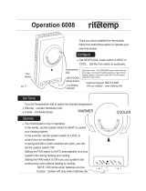
Figure 1 - CM Chassis
DIMENSIONAL/PHYSICAL DATA
FRONT
Water Coil
Connections
5/8" ID Tube Condensate
Drain Connection
H2O IN
H2O OUT
J Box
High Volt
Connections
Rating
Plate
Wire Diagram
TOP
The Right Fit for Comfort 5 Made in USA

Figure 2 - CW Chassis
DIMENSIONAL/PHYSICAL DATA
Water Coil
Connections
5/8" ID tube Condensate
Drain Connection
TOP
FRONT
Rating Plate
Wire Diagram
J Box
High Volt
Connections
The Right Fit for Comfort 6 Made in USA

Figure 3 - WM Chassis
DIMENSIONAL/PHYSICAL DATA
Water Coil
Connections
5/8" OD Pipe
Condensate
Drain Connection
TOP
FRONT
Install 2" x ¹∕₂" foam tape
Wire Diagram
Rating
Plate
J Box
High Volt
Connections
The Right Fit for Comfort 7 Made in USA

DIMENSIONAL/PHYSICAL DATA
Figure 4 - WM Right Chassis And Installation Kit Contents
TOP
FRONT
Wire Diagram
Rating Plate
5/8" OD Pipe
Condensate
Drain
Connection
Water Coil
Connections
J Box
High Volt
Connections
The Right Fit for Comfort 8 Made in USA

PRODUCT DESCRIPTION
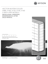
Figure 5 - CM Chassis
Figure 6 - CW Chassis
Thermostat
Fan Speed Switch (FSS)
System Switch (SS)
Slave
Master
CONDITIONED AIR
H20
OUT
H20
IN
Rating Plate
Wire Diagram
INLET AIR
High Volt
Connection
Optional
CONDITIONED AIR
H20
OUT
H20
IN
Thermostat
Fan Speed Switch (FSS)
System Switch (SS)
Low Volt Program Relay
High Volt
Connection
INLET AIR
Rating Plate
Wire Diagram
Optional
The Right Fit for Comfort 9 Made in USA

PRODUCT DESCRIPTION
Figure 7 - WM Chassis (Left)
Figure 8 - WM Chassis (Right)
SYSTEM SWITCH (SS)
FAN SPEED SWITCH (FSS)
THERMOSTAT
INLET AIR
CONDITIONED AIR
H20
OUT
H20
IN
Filter
Wire
Diagram
Rating
Plate
SYSTEM SWITCH (SS)
FAN SPEED SWITCH (FSS)
THERMOSTAT
INLET AIR
CONDITIONED AIR
H20
OUT
H20
IN
CONDENSATE
DRAIN STUB
Filter
High Volt
Connection
Wire
Diagram
Rating
Plate
The Right Fit for Comfort 10 Made in USA

• Field-Installed Accessories:
– Remote thermostat
– Hydronic heat valves
– Cabinets
Optional Wall-Mounted Thermostats:
EMI thermostats.
– Single stage, cool/heat, thermostat that can be
used in all RetroAire cooling, heating or heat pump
applications.
– Thermostat has adjustable setpoint range of
between 45°F (7°C) and 90°F (32°C).
– Heat pump option is a 2 stage heat/cool thermostat
which allows for emergency heat.
Alternate Manufacturer Thermostat
– Choose a single stage heat/cool, 24v thermostat.
– Straight cooling with electric heat or hydronic
heat. Select a thermostat compatible with cooling/
electric heat system. Thermostat should have “R”,
“Y”, “W” and “G” terminals.
– Heat pump, select a thermostat compatible with
cooling/single-stage heat/heat pump system.
Thermostat should have “R”, “Y”, “O” and “G”
terminals. RetroAire units are single stage heat-
ing only.
GENERAL PRODUCT INFORMATION
Product Description
• Water Source Console units are available as heat pump
systems. Model CW is available as straight cool.
• R-410A refrigerant.
• Provided high-efciency rotary compressor.
• Provided enhanced high-efciency heat exchanger.
• Two fan speeds.
• Energy Efciency Rating(EER) in excess of 12.
• Coefcient of performance(COP) in excess of 4 for (heat
pump models only)
Standard Controls And Components:
• Construction
– 20-gauge galvanized steel Water Source Console
Units construction of chassis.
– Powder-coated evaporator drain pan.
– Foam strip seal for supply air duct.
• Air Systems
– Indoor fan motor is thermally-protected PSC type.
– Air-stream surfaces are insulated with ⅛” ber-
glass or ¼” (3.2 mm) Volara™.
– Indoor fan is forward curved type, directly
mounted to motor shaft.
• Controls
– Unit-mounted operating controls include
thermostat, fan speed control and heat/cool
switch.
– Remote mount controls include fan speed
control.
– High pressure switch.
– Low Temperature/Low water ow cut out switch
compressor lock out relay
– 4-Way reversing valve with solenoid activated
by line voltage. Solenoid is energized for cooling
mode. (Heat pump models only).
The Right Fit for Comfort 11 Made in USA

INSTALLATION PREPARATION
DANGER
Electrical shock hazard. Before opening existing
unit open power supply disconnect switch. Secure
in open position during installation. Attach a sign
stating, “DO NOT TURN ON.”
Unplug existing unit at wall outlet. DO NOT plug in
new unit until installation is complete and start-up
checklist has been completed. Failure to do so will
result in death or severe personal injury.
!
WARNING
Moving parts can cause personal injury. Avoid
contact with moving parts when testing or servicing
the unit.
!
Chassis and Grills
• Secure existing front panels with screws that prevent
contact with all parts.
• Minor dimensions of openings must not exceed ½ inch
(12.5mm).
• Dimensions of indoor air discharge grill must not be less
than 26” x 4”. Grill must separate top surface of chassis
from top surface of discharge grill by minimum of 1 in
(25.4mm).
Electrical Supply
• Each unit must have separate branch circuit protected
by a fuse or breaker. Refer to rating plate for proper
wire and breaker or fuse size.
• Use of extension cords is prohibited.
• DO NOT connect RetroAire unit to circuit with
incorrectly-sized over current protection device.
• All cord-connected 265 volt units must be plugged into
receptacles within unit subbase or chassis.
Electrical Power Connection
• Verify RetroAire unit rating plate for circuit ampacity and
required breaker or fuse size.
• Verify existing breaker or fuse is correct size.
• Replace breaker or fuse if incorrectly-sized.
• Breakers must be type HACR only.
• Cord-connected units — verify wall outlet is correct
rating. Outlet’s blade conguration must match cord
supplied with RetroAire unit.
• Hard-wired units — verify power wiring is correctly
sized. Inspect existing wiring for any deciencies, such
as cuts or frayed wires. Replace such wiring if found.
• Refer wire diagrams for wire connections.
Remove Old Chassis
• Disconnect power or unplug cord before proceeding.
• Remove cabinet from old chassis.
• Disconnect water supply to coil.
• Disconnect condensate drain piping
• Remove any fasteners holding old chassis to sub base or
wall and remove chassis.
NOTICE
Dispose of old chassis following existing state and
federal regulations.
The Right Fit for Comfort 12 Made in USA

INSTALLATION
Installation
1.
See instructions for specic RetroAire unit.
2.
DO NOT connect power to unit or plug in cord until
instructions in this manual have been completed.
3.
Place new chassis in same place where old chassis
stood. Secure to subbase or wall as older unit was
secured.
4.
Check hose for cracks and/or brittleness, replace with
new hoses if any damage is found. Pipe new chassis
with same hoses.
5.
Hard piping, there should be union between unit and
hand shut off valve for service or removal of unit.
Connect condensate tube, and route to adequate drain.
6.
Plug line cord into receptacle.
• If hard wired; connect power wiring to unit wires in
J-box. See wiring diagram on unit. Follow instructions
on page 12 to verify existing wiring and over-current
protection.
• Remove line cord wires from Water Source Console
Units power entrance terminals. Route power supply
wiring through strain-relief bushing and connect leads
to power entrance terminals.
• Secure strain-relief clamp. If wiring is through conduit,
insert conduit through control box knockout and
secure in place.
• DO NOT turn on power until completing instructions in
“Final Inspection and Startup” on page 14.
7.
Open water valves. Bleed air from water lines with air
vent (if used) or by uncoupling return water line allow
any air to escape.
• If water appears dirty entire water system should be
ushed with proper cleaners to obtain PH value of 7
or 8.
• Take care if any sort of glycol(antifreeze) is being
used when cleaning system. Be careful not to let uid
get on any carpeting etc.
8.
DO NOT PLUG LINE CORD IN, if in used condition.
9.
Follow instructions in “Final Inspection and Startup” on
page 14.
The Right Fit for Comfort 13 Made in USA

FINAL INSPECTION AND START-UP
Before Operating Unit
☐ Verify electrical supply matches electrical
requirements of the unit, and unit is properly
grounded.
☐ Examine control box. Ensure all wire connections
are secure.
☐ Verify chassis is properly tted to cabinet and
securely mounted to sub base or oor.
☐ Make sure chassis is level.
☐ Pour water into drain pan and verify it ows from
drain pan to condensate drain
☐ Verify indoor blower wheels are secured to motor
shaft, and rotate freely.
☐ Ensure all sheet metal panels are in place and
secure.
☐ Attach front panel to existing cabinet enclosure.
☐ Verify nothing interferes with room discharge air
or return air of units.
– Check for curtains or drapes that obstruct air ow.
– See Figures 9 and 10.
– Check for plush carpeting that can obstruct return
air.
– Items like these can cause serious damage to
chassis.
☐ Any obstruction of supply air, including use of
deector bafes, may cause condensate to form on
louver or cabinet . See Figure 9).
☐ To ensure optimum performance of your Water Source
Console Unit, avoid restricting air ow. Position of
curtains or drapes over supply air grille may cause
air to recirculate without cooling the room. Unit will
short cycle and may cause premature compressor
failure. See Figure 10.
Figure 9 - Proper Air Flow Diagram
Figure 10 - Restricted Air Flow Diagram
The Right Fit for Comfort 14 Made in USA

FINAL INSPECTION & START-UP
Start Up
Initiate proper unit start up.
1.
Adjust all hand water valves to full open position. Turn
power on to the units. If when taking old unit out you
marked the position of hand water valve handle put it
back to that position rather than full open.
2.
Operate each unit in cooling cycle rst.
• Set thermostat temperature lower than room
temperature and depress "Cool" button.
• Entering water temperature (EWT) should be at
least 60°F (16°C). for start up.
• Unit will start discharging cool air.
• After unit has been running about 5 minutes check
temperature of EWT and leaving water temperature
(LWT). difference should show higher LWT by
about 10-12°F (6-7°C). If you nd you have this
difference you also have correct water ow. If
the difference is less then 10-12°F (6-7°C) you
have too much water owing through the unit. If
difference is higher you don’t have enough water
owing through the unit. Adjust the hand water
valve to get the temperature difference needed.
3.
Check unit heating operation. Turn thermostat to
slightly above room temperature. Depress "Heat"
button. Compressor and fan operate. After about 5
minutes of operation check water temperature of EWT
& LWT. For correct water ow adjust hand valves until
LWT is 6°F (3°C) less than EWT.
4.
Unit Mount ACO (Automatic change-over) with Fan
Cycle Switch (Optional). This option allows evaporator
fan cycle to run continuously. Place switch in cycling
position evaporator fan only runs when unit is calling
for heat or cooling. When switch is placed in “constant”
position, evaporator fan runs continuously unless unit is
physically turned off.
Three factors determine operating limits of RetroAire heat
pump units:
1. Return air temperature
2. Water temperature
3. Ambient temperature
Whenever any one of these factors is at minimum or
maximum level, other two factors must be at normal levels
to ensure proper unit operation.
Operating Limits
WMH/CM/CW Operating Limits
Air & Water Limits Cooling°F(°C) Heating°F(°C)
Min. Ambient Air 50(10) 50(10)
Rated Ambient Air 80(27) 70(21)
Max. Ambient Air 100(38) 85(30)
Mim. EAT 50(10) 70(21)
Rated EAT DB/WB 80/67(27/20) 60(16)
Max. EAT DB/WB 100/83(38/29) 80(27)
Rated *EAT DB/WB
°F
80/67(27/20) 70/60(21/16)
Rated**EWT
°F
85(30) 70(21)
Rated***LWT
°F
95(35) N/A
Max.EWT
°F
95/71(35/22) 80/67(27/20)
Max.EWT
°F
95(35) 90(33)
Min.*EAT DB/WB
°F
67/57(20/14) N/A
Min.*EWT
°F
65(19) N/A
Water Limits Cooling°F(°C) Heating°F(°C)
Min. EWT 60(16) 60(16)
Normal EWT 85(30) 70(21)
Max. EWT 95(35) 90(33)
(*'EAT' and Ambient Temperature surrounding the unit are same value)
STARTING CONDITIONS
Unit starts and operates with entering air temperature(EAT)
of 50°F(10°C) and entering water temperature(EWT) of
60°F(16°C) with both air and water at ow rates used in
AHRI Standard 320/86 rating test, for initial start up in win-
ter. This is start up only, not long running time.
If unit fails to operate:
A. Check voltage and current is in accordance with
electrical specications on unit rating plate.
B. Look for wiring errors. Check for loose terminals or
wire nuts where wire connections have been made
on both line and low-voltage terminal boards.
C. Check for water leaks around hose swivel joints.
If hard piped check all joints. After unit is running
check for leaks around condensate drain hose and
connection.
D. Verify High Pressure Switch (HPS) did not trip.
Cycle system switch off to reset lockout relay.
E. Determine if fan operates during heating and cool-
ing modes.
If these checks fail to reveal a problem and unit will not
operate, contact a service technician for proper diagnosis.
The Right Fit for Comfort 15 Made in USA

FINAL INSPECTION & START-UP
Unit Mounted Thermostat - See Figure 11.
1.
Place Water Source Console Units in "COOL", "HEAT",
or "OFF" position. Test operation in all positions.
2.
Place fan in either LOW or HIGH speed using fan speed
switch. Test operation in both positions for heating and
cooling.
3.
Test operation of optional Fan Cycle switch. Toggle
switch located on side of control box. With switch set
ON (continuous fan operation) or AUTO (cycling with
thermostat) for both heating and cooling. Set switch in
desired position.
4.
Rotate thermostat knob counter clockwise to
increase setpoint temperature, or clockwise to
decrease. Turn unit-mounted thermostat knob counter
clockwise until it stops produces warmest room
temperature, while turning it clockwise until it stops
produces coolest. Adjust setting for personal comfort.
Figure 11 - Typical Unit Mount Control
Boiler-less Control Operation-Optional
– Heat pump units with optional Boiler-less control
and electric heat, heat pump and electric heat
do not operate simultaneously.
– Boiler-less control monitors incoming water
temperature to heat exchanger and when it
drops below approximately 50°F control will
change from heat pump operation to electric
heat.
NOTICE
DO NOT rotate thermostat knob back and forth from
heating to cooling. This causes compressor to cycle
on and off rapidly and will cause damage to the
compressor. Allow compressor to remain off for at
least three minutes prior to restarting the unit.
Remote Mounted Thermostat
1.
Place thermostat in either “COOL”, “HEAT”, or “OFF”
position. Test operation in all positions.
2.
If thermostat is tted with fan switch, set as desired
places fan in either “ON”, “OFF”, or “AUTO”. Test
operation in all positions.
3.
Check thermostat calibration for both heating and
cooling operation.
Straight Cooling Water Source Console Units
Cooling Cycle
NOTICE
When unit is rst powered up, high humidity conditions
may cause condensation to form on the discharge grill.
Keep doors and windows closed to reduce humidity allow-
ing condensation to evaporate.
Room temperature must be above 65°F (18°C) for
compressor to operate in cooling mode on Water
Source Console Units with unit-mounted controllers.
1.
Place thermostat or system switch in COOL position.
2.
Adjust thermostat to cooler temperature until indoor
fan starts running. Compressor should turn on and
cold air begin to ow from the unit. Let unit continue
operating to cool the room and remove humidity.
3.
After unit starts running and space gets cooler, adjust
thermostat to warmer temperature until compressor
cycles off.
4.
If colder room temperature is desired, adjust
thermostat to cooler temperature setting, turning
compressor and fan back on.
5.
If warmer room temperature is desired, adjust
thermostat to warmer temperature setting, compressor
stops.
6.
Place thermostat or system switch in OFF position.
All operation should stop.
Heating Cycle — Electric Option
Room temperature must be below 85°F (29.4°C) to
energize the heater on Water Source Console Units
with unit-mounted controllers.
1.
Place thermostat or system switch in HEAT position.
2.
Adjust thermostat for warmer temperature until
indoor fan starts running and electric heater coil starts
emitting heat.
3.
After unit starts running and space gets warmer, adjust
thermostat to cooler temperature until electric heater
turns off.
4.
If warmer room temperature is desired, adjust
thermostat to warmer temperature setting, which will
turn electric heater back on.
The Right Fit for Comfort 16 Made in USA

SEQUENCE OF OPERATION
5.
If cooler room temperature is desired, adjust
thermostat to cooler temperature setting until electric
heater turns off. Fan will stop.
6.
Place the thermostat or system switch to OFF position.
All operation should stop.
Heating Cycle — Hydronic Option
Verify the motorized valve is rated for correct voltage.
• Most RetroAire units with unit mount controls will power
hydronic valve that is same voltage as unit (ex: unit
rated 208/230V will power a 208/230V).
• Check the wiring diagram (located on the unit) and
voltage application for the specic unit.
• Other valve congurations and voltage options are
available. Consult Technical Service if unit voltage does
not match your valve application.
Room temperature must be below 85°F (29°C) for
hydronic heater to operate.
1.
Place thermostat or system switch in HEAT position.
2.
Adjust thermostat to warmer temperature. Following
occurs
– Motorized valve should open and allow hot
water to run through coil.
– Indoor fan will run, blowing air through hydronic
coil.
– Signal to water valve continues until room
temperature rises above setpoint by 3°F (2°C).
3.
After unit starts running and area warms, adjust
thermostat to cooler temperature, hydronic valve closes
and indoor fan switches off.
4.
If warmer room temperature is desired, adjust
thermostat to warmer temperature setting, which
opens hydronic valve and turns on the indoor fan.
5.
If cooler room temperature is desired, adjust
thermostat to cooler temperature setting. Hydronic
valve will close and fan stops.
6.
Place thermostat or system switch to OFF position.
All operation should stop.
Heat Pump Water Source Console Units
Unit is equipped with a reversing valve that is energized for
cooling and de-energized in heating mode.
Cooling Cycle — Heat Pump Units
Room temperature must be above 65°F (29°C) for
compressor to operate in cooling mode on Water
Source Console Units with unit-mounted controllers.
1.
Place thermostat or system switch to COOL.
2.
Adjust thermostat to cooler temperature until indoor
fan starts running. Compressor will turn on and cold
air begins to ow from the unit. Allow unit to continue
operating cooling the room and remove humidity.
3.
After unit starts running and space gets cooler, adjust
thermostat to warmer temperature until compressor
cycles off.
4.
If colder room temperature is desired, adjust
thermostat to cooler temperature setting, turning
compressor and fan back on.
5.
If warmer room temperature setting is desired, adjust
thermostat to warmer temperature. Cooling mode
ceases and compressor and fan stop.
6.
Place thermostat or system switch to OFF.
All operation should stop.
Heating Operation — Heat Pump Units — Entering
Water Temperature Above 60°F (16°C)
Room temperature must be below 85°F (29°C)
for the compressor to operate in heating mode on
Water Source Console Units with unit-mounted
co
ntrollers
.
1.
Place thermostat or system switch to HEAT position.
2.
Adjust thermostat to warmer temperature setting
until
compressor and fan start running.
Warm air will
begin to ow from unit.
3.
After unit starts running and space warms, adjust
thermostat to cooler temperature until fan and
compressor turn off.
4.
For warmer room temperature,
adjust thermostat
to warmer temperature
setting
turning fan, and
compressor back on
.
5.
If cooler room temperature is desired,
adjust
thermostat to cooler temperature setting
. Heating
mode ceases and
compressor and fan will stop.
6.
Place thermostat or system switch in OFF position.
All operation should stop.
The Right Fit for Comfort 17 Made in USA

SEQUENCE OF OPERATION
Auxiliary Heating Operation — Electric Option
Room temperature must be below 85°F(29°C) to
energize heater on Water Source Console Units with
unit-mounted controllers.
1.
Place thermostat or system switch to HEAT position.
2.
Adjust thermostat to warmer temperature until fan
starts running and electric coil starts emitting heat.
3.
After unit starts running and space warms, adjust ther-
mostat to cooler temperature until electric heater and
fan turn off.
4.
If warmer room temperature is desired, adjust ther-
mostat to warmer temperature setting, which turns
electric heater and fan back on.
5.
If cooler room temperature is desired, adjust thermo-
stat to cooler temperature setting until electric heater
and fan turn off.
6.
Place thermostat or system switch to OFF position.
All operation should stop.
Auxiliary Heating Operation— Hydronic Option
Room temperature must be below 85°F (29°C) for
hydronic heater to operate on Water Source Console
Units with unit-mounted controllers. Hydronic valve
is 24Vac normally open valve. Should power be lost
to the unit, valve defaults to open position.
1.
Place thermostat or system switch to HEAT position.
2.
Adjust thermostat to warmer temperature.
Following occurs:
– Motorized valve opens and allows hot water to
run through coil.
– Indoor fan runs, blowing air through hydronic
coil
– Signal to water valve continues until room tem-
perature rises above setpoint by 3°F (2°C).
– After unit starts running and space gets warm-
er, hydronic valve closes and fan turns off.
3.
After unit starts and space warms, adjust thermostat to
cooler temperature setting, hydronic valve closes and
fan turns off.
4.
If warmer room temperature is desired, adjust thermo-
stat to warmer temperature setting, which opens the
hydronic valve and turn fan on.
5.
If cooler room temperature is desired, adjust ther-
mostat to cooler temperature setting. Hydronic valve
closes and fan turns off.
6.
Place thermostat or system switch to OFF position.
All operation should stop.
The Right Fit for Comfort 18 Made in USA

MAINTENANCE
DANGER
Electrical shock hazard. Disconnect power to
replacement units before servicing or accessing
control compartment. Failure to do so could result in
severe personal injury or death.
!
NOTICE
It is illegal to discharge refrigerant into the
atmosphere. Use proper reclaiming methods and
equipment when servicing a replacement unit.
Monthly Inspection And Maintenance
For optimum performance and reliability recommend
following inspections and maintenance monthly. Units
installed in harsh or dirty environments require more
frequent inspections and maintenance.
• Disconnect power to unit and remove necessary access
panels.
• Clean or replace the return air lter. Clean or replace
the return air lter as needed.
Allowing dust to collect on the lter will cause unit to lose
efciency and eventually malfunction. Check lter at least
once a month. Some environments may require more
frequent replacement, depending on particulate in the air
stream.
• Vacuum return air grille surface.
• Inspect & clean chassis interior for rodent or insect
infestation.
• Clean & ush condensate drain pan.
• Ensure condensate drain is functioning properly.
• Inspect refrigeration tubing, especially braze joints,
for signs of refrigerant leaks (oil residue). Repair if
necessary.
• Inspect coil. Ensure dirt or debris have not collected
on ns. Clean if necessary. Take care not to damage
coil ns when cleaning. Use n comb to straighten any
bent ns.
• Examine control box. Ensure all wire connections are
secure.
• Ensure blower wheels are secured to their motor shafts.
• Ensure dirt or debris have not collected on blower
wheels. Use vacuum and soft brush to clean if
necessary.
• If unit has hydronic option installed, inspect piping,
especially braze joints, for signs of water leaks. Repair
if necessary.
• Clean exterior of cabinet as desired with mild soap or
household cleaner.
• In event limit switch opens and de-energizes electric
heat, limit switch will need to be manually reset.
To reset switch:
☐ Remove control box cover.
☐ Locate limit switch.
☐ Push in reset button on switch face. See Figure
12.
Figure 12 Manual Reset Limit Switch
Reset Button
*Note:
Button will pop
out when limit
switch opens.
Push in to reset.
Seasonal Start-Up And Maintenance
At the beginning of cooling and heating seasons, complete
mechanical check should be performed and maintenance/
inspections performed as described below.
Disconnect power to unit and remove necessary access
panels.
1.
Perform inspections and maintenance dened in
“Monthly start-up and maintenance.”
2.
Visually check equipment. Look for obvious changes
in unit such as damaged coils or evidence of extended
wear on any moving parts.
3.
Check for unusual odors, oil leaks, or stains on or
around coil and refrigerant lines. Presence of oil here
may indicate potentially serious problem such as
refrigerant leak (example — burned motor windings,
water, or refrigerant).
4.
Verify base pan is clean.
5.
Inspect all electrical connections. Look for frayed
wires and poor connections. Loose terminal ends will
eventually fail, causing loss of performance or possible
damage to equipment.
6.
Check fan motor and blower assemblies. Some units
may require drop of light oil to motors and/or bearing
assemblies, look for oil cups. Verify set-screws and
motor mounting hardware are tight.
7.
Brush and/or vacuum centrifugal fan blades and
blower cage assemblies, they must be clean to operate
efciently.
8.
If unit has hydronic option installed, inspect piping,
especially braze joints, for signs of water leaks. Repair
if necessary.
9.
Clean or replace return air lter.
10.
Vacuum return air grille surface.
11.
Inspect and clean chassis interior for rodent or
insect infestation.
The Right Fit for Comfort 19 Made in USA

TROUBLESHOOTING
12.
Inspect coils. Use n comb to straighten out any
damaged ns.
Coils must be clean for proper
operation.
Do not use solvent-based cleaner to clean coils,
some solvents produce noxious odor when unit is in
operation.
13.
Inspect and clean drain pan and drain line(s). Use of
anti-fungicide tablet to keep condensate system free
from bacterial contaminants is recommended.
14.
Verify unit is level. Over time building and equipment
may settle, causing shift in direction of condensate
ow.
15.
Replace access panels and reconnect electrical power.
16.
Test unit operation.
MAINTENANCE
Troubleshooting - Have qualied technician conduct troubleshooting procedures.
Symptom Suggestion
No heat or cooling
• Verify unit has power and thermostat is satised. If thermostat is not
satised, call your installing contractor or service contractor.
Thermostat calls for cooling, cool air is
not coming from unit.
• Check for continuity between thermostat and unit. Verify 24 Vac is
present across terminals C and R.
• Verify water is owing through water coil. Locate high pressure switch
reset button, push the button.
• Some units are equipped with LCDI (Leakage Current Detection
Interrupt) line cord. Verify line cord is reset by pressing reset button at
line cord plug.
•Note: If indoor fan is operational and all above suggested procedures
have been followed, and there is still no cooling being supplied by unit,
contact trained heating and cooling professional.
Thermostat calls for heat, no heat comes
from unit.
• Check to see if unit has power or thermostat has been satised. If
unit has power and thermostat is satised, set thermostat above room
temperature.
• Units equipped with electric heaters have temperature limit switch to
prevent electric heater from reaching unsafe temperatures. If after
calling for heating heater is not energized, check for continuity across
limit. If limit is open, replace with equivalent limit switch. Auto reset /
Manual reset Switch.
Thermostat calls for heat while in heat
pump mode, but no heated air comes
from unit.
• If unit is equipped with LCDI Line Cord, verify it is not tripped.
• While in heat pump mode, verify thermostat is not energizing O terminal.
RetroAire units are designed to work in heat pump mode when 24Vac is
present across Y and C.
• Verify unit has power or thermostat has been satised. If unit has power
and thermostat is satised, set thermostat above room temperature.
The Right Fit for Comfort 20 Made in USA
/