EMI R10/R20/R35/R45/R80/R90 Dual Motor PTAC Installation & Operation Manual
- Type
- Installation & Operation Manual

The Right Fit for Comfort
™
ECR International Inc
2201 Dwyer Avenue
Utica, NY 13501
e-mail: inf[email protected]
An ISO 9001-2008 Certified Company
P/N 240008034, Rev. E [5/16/2013]
R10C
/
H R20C
/
H R35C
/
H
R45C
/
H R90C
/
H
Packaged Terminal Air Conditioner (PTAC)
Packaged Terminal Heat Pump (PTHP)
Straight cooling nominal capacities
9,000 12,000 15,000 18,000 Btuh
2.6 3.5 4.4 5.3 kW
Heat pump nominal capacities
9,000 12,000 15,000 Btuh
2.6 3.5 4.4 kW
Installation, Operation,
& Maintenance Manual
R10C | R10H
Replacement for:
American Air Filter 16 series,
American Standard 45,
Carteret 45, Remington Type 45,
McQuay 45, Singer 45, Nelson Aire 16
R45C | R45H
Replacement for:
American Standard Type 40
R20C | R20H
Replacement for:
Climate Master (Friedrich) 702/703,
Cool Heat RM series,
TPI Ra-Matic, Weather Twin,
Zonaire S, SC & RM
R35C | R35H
Replacement for:
Singer, Remington,
McQuay EA, ES & RS
R90C | R90H
Replacement for:
Cool Heat AD & 700,
Friedrich Climate Master AD & 700

Read This First
To the installer
Retain this manual and warranty for future reference.
Before leaving the premises, review this manual to be sure the unit
has been installed correctly and run the unit for one complete cycle
to make sure it functions properly.
To obtain technical service or warranty assistance during or after
the installation of this unit, contact your local representative. Visit
our web site www.retroaire.com for a local representative listing.
For further assistance call 1-800-228-9364.
When calling for assistance, please have the following information
ready:
Model Number___________________________________
Serial Number____________________________________
Date of installation_________________________________
NOTICE
The RetroAire™ replacement PTAC/PTHP is backed by
EMI and ECR International and is tested and rated in ac-
cordance with:
AHRI Standards 310/380
UL-484
Due to ongoing product development, product designs and
specifi cations may change without notice.
Please contact the factory for more information.
Contents
Read This First 2-3
To the installer . . . . . . . . . . . . . . . . . 2
Inspection . . . . . . . . . . . . . . . . . . . 3
General precautions . . . . . . . . . . . . . . . 3
General Product Information 4-7
Product description . . . . . . . . . . . . . . . 4
Standard controls and components . . . . . . . . . 4
Factory-installed options
(consult the factory) . . . . . . 4
Field-installed options . . . . . . . . . . . . . . 4
R10C/R10H Chassis . . . . . . . . . . . . . . . 5
R20C/R20H Chassis . . . . . . . . . . . . . . . 5
R35C/R35H Chassis . . . . . . . . . . . . . . . 6
R45C/R45H Chassis . . . . . . . . . . . . . . . 6
R90C/R90H Chassis . . . . . . . . . . . . . . . 7
PTAC/PTHP Model Coding 8
Features 9-10
Optional wall-mounted thermostats . . . . . . . . .10
Preparing for the Installation of the PTAC/PTHP 11
Electrical power connection . . . . . . . . . . . .11
Remove the old chassis . . . . . . . . . . . . . .11
Installation Instructions — R10C
|
R10H 12-13
Installation Instructions — R20C
|
R20H 14-15
Installation Instructions — R35C
|
R35H 16-17
Installation Instructions — R45C
|
R45H 18-19
Installation Instructions — R90C
|
R90H 20-21
Sequence of Operation 22-23
Initial Power-Up or power restoration . . . . . . . .22
R_ _C / R_ _H: Cooling Operation . . . . . . . . . .22
R_ _C / R_ _H: Heating Operation . . . . . . . . . . 23
R_ _H: Mechanical Heating "Heat Pump" . . . . . . .23
R_ _H: Auxiliary Heating "Electric" or "Hydronic" . . . .23
Final Inspection & Start-up 24-29
Before operating the unit . . . . . . . . . . . . .24
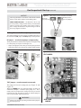
Setting the control board jumpers. . . . . . . . . .25
Start Up . . . . . . . . . . . . . . . . . . . .26
Unit-mounted thermostat . . . . . . . . . . . . .26
Remote-mounted thermostat . . . . . . . . . . .26
Straight cooling PTAC's . . . . . . . . . . . . 26-27
Heat Pump PTHP's . . . . . . . . . . . . . . 27-28
Start-up . . . . . . . . . . . . . . . . . . . .29
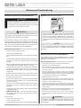
Maintenance & Troubleshooting 30-32
Monthly inspection and maintenance . . . . . . . .30
Seasonal start-up and maintenance . . . . . . . 30-31
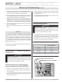
Heat pump units — temporary emergency heating mode 31
Troubleshooting sensors . . . . . . . . . . . . .31
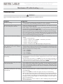
Troubleshooting . . . . . . . . . . . . . . . .32
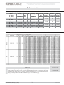
Performance Data 33
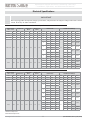
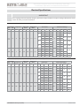
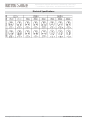
Electrical Speci cations 34-35
•
Insta
ll
ation, O
p
eration, an
d
Maintenance Manua
l
•
The Right Fit for Comfort 2 P/N 240008034, Rev. E [5/16/2013]

Read This First (continued)
General precautions
DANGER
Electrical Supply
Carefully read the rating plate located on the front panel.
The RetroAire replacement PTAC/PTHP must:
• Be properly connected to electrical supply with the
proper voltage as stated on the rating plate.
• Be properly grounded.
• Use the properly-sized over-current protection
device as stated on the rating plate. (time-delay fuse/
HACR Breaker)
Do not modify the RetroAire replacement PTAC/PTHP
Do not attempt to modify or change this unit in any way.
Tampering with the RetroAire replacement PTAC/PTHP is
dangerous and may result in serious injury or death. Tamper-
ing voids all warranties.
Power Cord
The power cord supplied with the RetroAire replacement
PTAC/PTHP should be checked before every use. Follow
the instructions in the order listed on the device. Do not use
the product if the cord fails the test. A damaged power supply
cord must be replaced with a new cord from the manufacturer
and not repaired. The use of extension cords is prohibited.
Failure to follow these instructions can result in a fi re, explo-
sion or electrical shock causing property damage, personal
injury or death.
WARNING — Safety instructions
Save these instructions — this manual is intended as an
aid to quali ed service personnel for proper installation,
operation, and maintenance of the RetroAire replacement
PTAC/PTHP.
Read all instructions thoroughly and carefully before at-
tempting installation or operation. Install or locate this unit
only in accordance with these instructions. Use this unit only
for its intended use as described in this manual.
Turn o the electrical supply before servicing the unit.
PTAC/PTHP chassis are heavy. To avoid injury, use assistance
when lifting.
Do not use the unit if it has damaged wiring, is not working
properly, or has been damaged or dropped.
Failure to follow these instructions may result in improper
installation, operation, service, or maintenance, possibly
resulting in fi re, electrical shock, property damage, personal
injury, or death.
Recognize this symbol as an indication
of important safety information.
Inspection
• Carefully check the shipment against the bill of lading.
• Make sure correct chassis has been received (as well as any
options).
• Verify your equipment by using “Model coding” on page 8 .
Verify unit:
• Unit size and type correct per submittal sheet and job requirements?
• Voltage correct?
Verify options (if any):
• Capacity, electric heat if used?
• Hydronic coil included, if required? Piping located as re-
quired?
• All other factory installed options installed, if any?
• All fi eld installed options included, if any?
Shipping damage MUST be reported to
the carrier IMMEDIATELY.
• Examine the exterior.
• Remove cover and examine
compressor and piping for signs
of damage.
• Inspect each component for damage.
• Concealed damage must be reported to the carrier
within 15 days of the receipt of the shipment.
• The carrier must make proper notation on the delivery
receipt of all damage identifi ed and complete a carrier
inspection report.
• The purchaser must notify ECR International’s Cus-
tomer Service department of all damage and is respon-
sible for fi ling any necessary claims with the carrier.
Customer Service : (800) 228-9364
Replacement Packa
g
ed Terminal Air-Conditionin
g
/ Heat Pum
p
•
Installation, O
p
eration, and Maintenance Manual
•
P/N 240008034, Rev. E [5/16/2013] 3 Made in USA

General Product Information
Product description
RetroAire Replacement Packaged Terminal Air Condition/Heat Pumps units
are available in straight cooling (PTAC) or as heat pump systems (PTHP).
Both the PTAC and PTHP confi gurations fi t the wall sleeves of the units listed
on the front cover. Heat pumps (PTHP) reduce energy costs and will operate
in mechanical heat mode down to an outdoor temperature of 40°F (4.4°C),
Below 40°F (4.4°C) heating is accomplished by an auxillary heat option.
The Retroaire PTAC/PTHP units:
• Use R-410A refrigerant. This refrigerant is not affected by a phase out
schedule.
• Include high-effi ciency rotary compressors, protected by a 5-year war-
ranty.
• Include an enhanced, high-effi ciency heat exchangers.
• Offer two fan speeds.
• Incorporate positive condensate re-evaporation to improve effi ciency.
• Have an optional motorized fresh-air feature with a positive pressure seal.
RetroAire PTAC/PTHP ratings meet or exceed ASHRAE 90.1 Standards
for energy effi ciency:
• PTAC/PTHP units are available in nominal sizes of 9,000 Btuh, (2.6kW)
12,000 Btuh (3.5kW) or 15,000 Btuh (4.4kW).
• PTAC units (straight cooling only) are also available at 18,000 Btuh
(5.3kW).
• Energy Effi ciency Rating (EER) as high as 10.
• Coeffi cient of performance (COP) ratings as high as 2.90 for heat pumps.
Standard controls and components
Construction
• 20-gauge galvanized steel construction of chassis.
• Condenser baffl e options to accommodate extended wall sleeve applica-
tions. (Consult the factory for special order items).
• Powder-coated condenser and evaporator drain pan.
• Foam strip seal for supply air duct.
• Weather strip insulation.
Air systems
• Motors are thermally-protected PSC type.
• Air-stream surfaces are insulated with ¹⁄
4" fi ber-glass or ¹⁄8" (3.2 mm)
Volara™.
• The indoor fan is a foward-curved type, directly mounted to the motor shaft.
• Unit mount controls include a fi eld selection switch to control indoor fan
by either cycling with compressor operation or continuously with the unit.
Condensate removal
• The outdoor fan incorporates condensate slinger ring — Condensate is
thrown onto the coil, where it evaporates, improving system performance.
• Thermostatic drain pan valve for condensate elimination when outdoor
temperature drops below 60°F (15°C) (heat pump units only).
Controls
• Unit-mounted operating controls include thermostat, fan speed control,
heat/cool switch, fan cycle switch, fresh air switch (if equipped)
• Ability to utilize 1-stage or 2-stage thermostat. 2 stage thermostat is ca-
pable of activating emergency heat if an auxiliary heat source is available.
• Low ambient protection — see "Microprocessor control board" for details.
• Ability to control a normally-open or normally-closed motor valve switch
(on hydronic heat units only). Valve controls must be ordered for 24V
or line voltage.
• All hydronic heat units include molex plugs for connection of hydronic
valve motor.
• Remote mount controls include fan speed control and fresh air switch
(if equipped)
• All units are equipped with manual reset high pressure switch which pre-
vents abnormal high pressure operation, increasing compressor reliability.
Microprocessor control board
• The universal control board is used in straight cooling, electric resistance
heat, hydronic heat, or cooling/heat pump applications.
• Random start timer prevents multiple units from simultaneous startups
after power interruption or on initial power-up.
• Fan purge — fan remains on for 60 seconds after heat/cool is satisfi ed.
• Anti-short-cycle compressor protection prevents the compressor from
rapid cycling, increases compressor reliability.
• Freeze-protection prevents evaporator coil freeze up, improving com-
pressor reliability.
• Low ambient lockout prevents compressor operation in outdoor tem-
peratures less than 40°F (4.4°C). (On PTHP units supplied with unit-
mounted control, the control causes automatic changeover to auxiliary
heat, if installed.)
• Test operation — all timers are temporarily suppressed to allow ease of
testing or troubleshooting.
• Control board LED provides self-diagnostic troubleshooting codes, see
"Sequence of operation."
Factory-installed options (consult the factory)
• 265/277V(12 and 15 only)
• 115V (09 &12 Models Only)
• Corrosion-resistant coil option — used for seacoast and harsh-
environment usage; coated aluminum fi n/copper tube condenser
coil.
• Motorized fresh-air damper
• Supplemental electric heat — see heat options on “Model cod-
ing” on page 8 .
• Hydronic heat controls
• Front air intake
Field-installed accessories
• Hydronic heat — the coil assembly is shipped loose for fi eld installation.
• Remote wall thermostat — digital 1-stage or 2-stage available.
• Wall sleeves, louvers, and cabinets
• Aquastat - delays fan start-up until coil reaches 100°F (38°C) to virtually
eliminate "cold" blow condition.
• Hydronic control valve , Water 2 way & 3 way
• Hydronic control valve, Steam 2 way
• Hydronic Isolation valve, 1/2 in Sweat Connection.
R
ep
l
acement Pac
k
age
d
Termina
l
Air-Con
d
itioning / Heat Pum
p
•
Insta
ll
ation, O
p
eration, an
d
Maintenance Manua
l
•
The Right Fit for Comfort 4 P/N 240008034, Rev. E [5/16/2013]

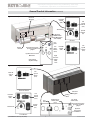
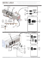
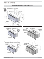
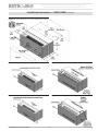
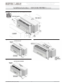
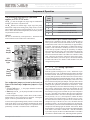
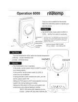
Figure 2 R20C
|
R20H chassis
Figure 1 R10C | R10H chassis
General Product Information (continued)
Fresh Air
Switch
(FAS)
Thermostat
Fan
Speed
Switch
(FSS)
System
Switch
(SS)
Line
Cord
Fan
Cycle
Switch
(FCS)
High
Pressure
Switch
(HPS)
reset
Aquastat Connection
(Factory) Installed
jumper
Aquastat Connection
(Factory) Installed
jumper
Hydronic Connection
MTR Valve
Hydronic
Connection
MTR Valve
Hydronic
NO/NC Switch
Valve Orientation
Switch (VOS)
Rating
Plate
Electrical
Diagram
Fresh Air
Switch
(FAS)
Fan
Speed
Switch
(FSS)
Remote
Unit Mount
Valve Switch
(Hydronic Only)
Fan Cycle
Switch (FCS)
Fresh Air
Switch
(FAS)
Thermostat
Fan
Speed
Switch
(FSS)
System
Switch
(SS)
Rating
Plate
Electrical
Diagram
Line
Cord
High Pressure
Switch (HPS)
reset
Remote Mount
Unit Mount
Fresh Air
Switch
(FAS)
Fan
Speed
Switch
(FSS)
Replacement Packa
g
ed Terminal Air-Conditionin
g
/ Heat Pum
p
•
Installation, O
p
eration, and Maintenance Manual
•
P/N 240008034, Rev. E [5/16/2013] 5 Made in USA

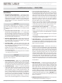
Figure 4 R45C
|
R45H chassis
Figure 3 R35C
|
R35H chassis
Thermostat
Fan
Speed
Switch
(FSS)
System
Switch
(SS)
Line
Cord
Fan
Cycle
Switch
(FCS)
High
Pressure
Switch
(HPS)
Aquastat
W/ Jumper
MTR Valve
Hydronic
NO/NC Switch
Valve Orientation
Switch (VOS)
Rating
Plate
Electrical
Diagram
Fresh
Air
Switch
Fresh Air
Switch
(FAS)
Fan
Speed
Switch
(FSS)
Remote
Unit Mount
Fresh Air Switch
(FAS)
Thermostat
Fan
Speed
Switch
(FSS)
System
Switch
(SS)
Line
Cord
Fan
Cycle
Switch
(FCS)
High
Pressure
Switch
(HPS)
Aquastat
W/ Jumper
MTR Valve
Rating
Plate
Electrical
Diagram
Fresh Air
Switch
(FAS)
Fan
Speed
Switch
(FSS)
Remote Mount
Unit Mount
R
ep
l
acement Pac
k
age
d
Termina
l
Air-Con
d
itioning / Heat Pum
p
•
Insta
ll
ation, O
p
eration, an
d
Maintenance Manua
l
•
The Right Fit for Comfort 6 P/N 240008034, Rev. E [5/16/2013]

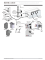
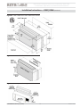
Option A
Option B
Option C
Figure 5 R90C | R90H chassis
Fresh Air Switch
(FAS)
Line
Cord
Fan
Cycle
Switch
(FCS)
High
Pressure
Switch
(HPS)
Aquastat
W/ Jumper
MTR
Valve
Hydronic
NO/NC Switch
Valve Orientation
Switch (VOS)
Rating
Plate
Electrical
Diagram
Molex
Connector
from control
Board
Thermostat
Fan
Speed
Switch
(FSS)
Fan
Speed
Switch
(FSS)
System
Switch
(SS)
Thermostat
System
Switch
(SS)
Plug
Molex
connector
from unit
Strain
Relief
T-Stat
Rear of
Control Box
Option A & C
Unit Mount
Option A & C
Remote Mount
Option B
Unit & Remote
Mount
Replacement Packa
g
ed Terminal Air-Conditionin
g
/ Heat Pum
p
•
Installation, O
p
eration, and Maintenance Manual
•
P/N 240008034, Rev. E [5/16/2013] 7 Made in USA

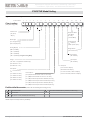
PTAC/PTHP Model Coding
Product Series
[
10, 20, 35,
45, 90
]
Design Revision
[
A
= revision level ]
Open Options
[
A
= standard ]
Open Options
[
A
= standard ]
Compressor Codes
[
A
= TECH ]
[
L
= LG ]
[
T
= TOSHIBA ]*
Standard/Special
[
0
= standard ]
[
A-Z
= special option ]
Air Options
[
A
= no fresh air damper ]
[
B
= with fresh air damper ]
[
C
= front air intake, no fresh air damper ]
[
D
= front air intake, with fresh air damper ]
Heat Options
[
0
= no electric heat ]
[
2
= 2 KW electric heat ]
[
3
= 3 KW electric heat ]
[
4
= 4 KW electric heat ]
[
5
= 5 KW electric heat ]
Control Options
[
0
= (UM) unit-mount with elec. heat or no elec. heat ]
[
1
= (RMT) remote tstat with elec. heat or no elec. heat ]
[
2
= (UM) unit-mount hyd. heat N/O or N/C valve (line volt.) ]
[
3
= (RMT) remote tstat hyd. heat N/O or N/C valve (line volt.) ]
[
4
= (UM) unit-mount hyd. heat N/O or N/C valve (24 volt.) ]
[
5
= (RMT) remote tstat hyd. heat N/O or N/C valve (24 volt.) ]
Voltage
[
A = 115 V / 1 / 60 ] (Models 9 & 12 BTU only)
[ D = 208/230 V / 1 / 60 ]
[
E = 265/277 V / 1 / 60 ]
Chassis coding
[verify with rating plate]
Position number: 1 2 3 546789101112131415
R
Cooling Capacity
[
09
= 9,000 Btuh ]
[
12
= 12,000 Btuh]
[
15
= 15,000 Btuh]
[
18
= 18,000 Btuh] (Straight Cooling Only)
Figure 6 Model coding
Remote thermostat Sea Coast Coated Coils (Factory Installed, consult factory)
Hydronic Heat
Wall Sleeves. Louvers, & Cabinet (Consult Factory)
Field Installed Accessories [items to be selected during the ordering process]
Chassis Type
[
C
= straight cooling ]
[
H
= heat pump unit ]
*Toshiba compressors subject to factory availability
R
ep
l
acement Pac
k
age
d
Termina
l
Air-Con
d
itioning / Heat Pum
p
•
Insta
ll
ation, O
p
eration, an
d
Maintenance Manua
l
•
The Right Fit for Comfort 8 P/N 240008034, Rev. E [5/16/2013]

Features
Indoor coil freeze protection (standard)
This feature will prevent the indoor coil from freeze up in the cooling
mode.
• Indoor coil freeze up can occur due to a dirty air fi lter, restricted
or poor air fl ow, low refrigerant charge or low room or outdoor
temperatures.
• This in turn can cause compressor damage.
• Should a freeze condition be detected, the compressor and outdoor
fan will be switched off for a minimum of three minutes until the
freeze condition is satisfi ed.
• During this time the indoor fan will continue to run to aid in the
defrost process.
Condensate removal (standard)
The RetroAire replacement unit (cooling operation) is designed to
eliminate condensate by slinging it onto the outdoor coil.
• Condensate drains through the bulkhead to the area near the outdoor
fan.
• As part of its normal operation, the unit will produce condensate
and collect it in the base pan of the unit. There it is picked up by
the outdoor fan slinger ring and deposited onto the condenser coil.
During the cooling season, this improves the unit’s effi ciency by
maintaining reduced refrigeration system pressures.
• Base pan has overfl ow notches, if too much condensate is produced
notches allow condensate to fl ow out of the basepan and into the
wallsleeve out of the building.
Thermostatic drain pan valve
(standard on heat pump units)
On heat pump models (PTHP), condensate can accumulate in the outdoor
drain pan during the heat pump cycle.
• PTHP units include a thermostatic drain valve that opens when
outdoor temperatures fall below 60°F (15°C).
• When the drain valve opens, condensate fl ows from the drain pan
onto the bottom of the wall sleeve, where it drains to the outside.
• This keeps the base pan free of condensate water, which could oth-
erwise freeze during colder outdoor temperatures.
Random start feature (standard)
The random start feature is initiated on initial power-up or after a power
interruption.
• The controller adds a random time delay (from 5–120 seconds) on
start-up, preventing the compressor from starting.
• This staggers the starting of multiple units in a single facility, prevent-
ing a large surge that might occur if all units started at the same time.
Anti-short cycle timer (standard)
The microprocessor control uses this timing to prevent short-cycling
of the compressor.
• When the compressor cycles off on a heating or cooling call, the
controller starts a 180-second timer.
• The compressor will not be allowed to start until this time has elapsed.
• On initial power-up or after a power failure, this timing occurs after
the random start timing.
Power co rd with integral safety protection
(standard)
All PTAC/PTHP units rated 250v or less are equipped with a
power cord with integral safety protection as standard.
• Providing personal shock protection as well as arcing and fi re pre-
vention, the device is designed to sense any damage in the line cord
and disconnect power before a fi re can occur.
• Tested in accordance with Underwriters Laboratories, the cord set
also offers a unique “passive” operation, meaning the unit does not
require resetting if main power is interrupted.
Heat pump
Heat pump units are “Limited Range” and should be equipped
with back-up electric resistance or hydronic heat. Limited Range
heat pumps are designed to operate when outdoor temperatures
are between 75°F(24°C) and 40°F(4.4°C) and with a maximum
indoor temperature of 80°F(26.6°C). The unit is equipped with
a reversing valve that is energized for cooling and de-energized
in heating mode. Electric heating or hydronic heat will operate
using the onboard control logic below the operating conditions
of the heat pump.
Hydronic heating (optional)
An optional hydronic heat package may be selected in lieu of electric
heat. Heating operation is essentially the same as that of units with
electric heat.
Aquastat connection (optional)
All replacement PTAC/PTHP's with hydronic heat are supplied with
a standard line volt Aquastat connection. The fi eld installed Aquastat
delays the fan operation until the hydronic coil reaches a temperature
of 100°F (38°C).
•
Installation, O
p
eration, and Maintenance Manual
•
P/N 240008034, Rev. E [5/16/2013] 9 Made in USA

Motorized fresh air damper (optional)
The optional motorized fresh air damper allows fresh air into
the space to be conditioned. When the Fresh Air switch is in
the "YES" position the damper door is open and allows fresh
air into the space. This feature is only available when the indoor
fan is on. When the damper door switch is in the "NO" position,
the damper door is closed and does not allow air in the space.
Optional wall-mounted thermostats
Thermostats available from EMI
EMI offers a thermostat that is compatible with your PTAC/
PTHP unit.
• Select EMI part number 240008208 from the latest RetroAire
price list for this option. This is a single stage, cool/heat,
thermostat that can be used in all RetroAire cooling, heating
or heat pump applications.
• The thermostat has an adjustable setpoint range of between
45°F(7°C) and 90°F(32°C).
• For heat pumps another option is EMI part number 240008209.
This is a 2 stage heat/cool thermostat which allows for emer-
gency heat.
Selecting a thermostat (by others)
When selecting a thermostat other than one offered by EMI,
choose a single stage heat/cool, 24v thermostat.
Straight cooling with electric heat or hydronic heat
(R10C
— PTAC's)
Select a thermostat that is compatible with a cooling/electric
heat system.
The thermostat should have “R”, “Y”, “W”, "C" and “G” ter-
minals.
Heat pump with electric heat (R__H - PTHPs)
Select a thermostat that is compatible with a cooling/single-stage
heat/heat pump system.
The thermostat should have "R", "Y", "O" and "G" terminals.
RetroAireunits are single stage heating only.
The eleactric heat and heat pump will not operate simultaneously.
Features
R
ep
l
acement Pac
k
age
d
Termina
l
Air-Con
d
itioning / Heat Pum
p
•
Insta
ll
ation, O
p
eration, an
d
Maintenance Manua
l
•
The Right Fit for Comfort 10 P/N 240008034, Rev. E [5/16/2013]

Preparing for the Installation of the PTAC/PTHP
WARNING
Moving parts can cause personal injury. Avoid contact
with moving parts when testing or servicing the unit.
Verify existing wall sleeve/enclosure:
RetroAire replacement PTAC/PTHP's are to be used with
metal wall sleeves.
The existing front panels must be secured by screws that
prevent contact with all parts.
Minor dimensions of openings must not exceed ½ inch
(12.5mm).
The indoor air discharge grill must have dimensions not
less than 26” x 4”. The grill must separate the top surface
of the chassis from the top surface of the discharge grill by
a minimum of 1 in (25.4mm).
For all models, the outdoor openings must prevent contact
of all moving parts by means of louvers or grills, with minor
dimension not exceeding 1 in (25.4mm).
Electrical supply
Each unit must have a separate branch circuit protected
by a fuse or breaker. Refer to the unit rating plate for the
proper wire and breaker or fuse size. Use of extension
cords is prohibited.
DO NOT connect the RetroAire unit to a circuit with an
incorrectly-sized overcurrent-protection device.
All cord-connected 265-volt units must be plugged into
receptacles within the unit subbase or chassis.
Electrical shock hazard — Before opening the existing
unit:
Open the power supply disconnect switch. Secure it in an
open position during installation. Attach a sign stating, "
DO
NOT TURN ON.
"
On a plug and receptacle connection, unplug the existing unit
at the wall outlet. DO NOT plug in the new unit until installa-
tion is complete and the start-up checklist has been completed.
Failure to comply with the above could result in severe
personal injury, death or substantial property damage.
NOTICE
All wiring should be in accordance with both the National
Electric Code (NEC) and the local building codes.
UNITS RATED 208/230V — the RetroAire unit is wired
for 230v primary voltage from the factory. The transformer
must be rewired by the installer if the jobsite voltage is
208v. Change the transformer tap from orange to red. See
the wiring diagram for details.
Electrical powe r connection
1. Check the RetroAire unit rating plate for circuit ampacity
and required breaker or fuse size.
2. Verify that the existing breaker or fuse is the correct size.
a. Replace the breaker or fuse if incorrectly-sized.
b. Breakers must be type HACR only.
3. Cord-connected units — verify that the wall outlet is the
correct rating. The outlet's blade confi guration must match
that of the cord supplied with the RetroAire unit.
4. Hard-wired units — verify that the power wiring is correctly
sized. Inspect the existing wiring for any defi ciencies, such
as cuts or frayed wires. Replace such wiring if found.
Remove the old chassis
1. Disconnect power or unplug cord before proceeding.
See WARNING at left.
2. Remove the front of the existing room enclosure to expose
the old chassis.
3. Loosen any tie-down bolts or screws and remove the old
chassis.
NOTICE
Dispose of the old chassis following existing state and
federal regulations.
4. Inspect the wall sleeve/cabinet for any rust, holes, or damage.
a. Clean the wall sleeve of any dirt.
b. Repair any damage.
c. Ensure proper drainage of condensate or rainwater to exterior
of building.
5. Remove or repair the old weather seals and make note of the
location for the installation of any new seals.
6. Check the wall sleeve/cabinet to ensure all drain holes are
open and that:
a. The wall sleeve/enclosure is level left to right
b. The back is pitched to the outside by ½in (12.5mm)
maximum.
7. Before installing the new chassis, inspect the outdoor louver
for a minimum free area of 70% and remove any obstruc-
tions. Obstructions will restrict air fl ow over the condenser
coil and may cause serious damage to the chassis. It will
also void the warranty.
8. See the instructions for the specifi c RetroAire unit on the
following pages.
9. DO NOT connect power to the unit or plug in the cord until
all instructions in this manual have been followed.
Replacement Packa
g
ed Terminal Air-Conditionin
g
/ Heat Pum
p
•
Installation, O
p
eration, and Maintenance Manual
•
P/N 240008034, Rev. E [5/16/2013] 11 Made in USA

Installation Instructions — R10C
|
R10H
Installation
1. Verify the existing wall thickness — The distance from
the condenser coil to the outdoor louver varies with sleeve
depth, unit(s) ship standard with 1 ³⁄8 "(35mm) & 1 ¹⁄2”(38mm)
baffl es. In addition, EMI stocks an optional condenser-side
air baffl e kit for chassis installation in deeper-than-standard
wall sleeves. For fast, trouble-free installation, know your
wall sleeve depth when ordering.
2. Verify weather angles — Slide the unit into the wall sleeve.
If the supply duct on the cooling chassis does not line up
with the supply vent on the room cabinet, it is possible that
the factory installed weather angle on the top and the sides
will have to be reversed. This will allow approximately 1”
(25.4mm) of adjustment for alignment with the supply vent
when mounting the unit to the wall sleeve (see Figure 8 and
Figure 9). Slide the unit back in the wall sleeve to verify
proper fi t.
3. Install the ba es — Slide the unit back out of the wall
sleeve. Remove both sets of baffl es from the kit bag supplied
with unit. Install only one set of left and right side baffl es on
the condenser coil
by completing steps below
:
• Choose the proper fi tting baffl es for your application by
verifying selected baffl es come in contact with the outdoor
louver.
• Make sure the baffl es are directed inward toward the center
of coil (see Figure 10).
• Secure baffl es tightly into the existing holes of the condenser
coil using the screws provided.
NOTICE
The correct condenser air baffl es must be installed or perfor-
mances may be impaired.
4. Install the foam tape — Apply one piece of ¹⁄” x ¹⁄”
open-cell poly-foam to top fl ange of evaporator block off
(see FIgure 10).
5. Install the foam tape — Apply 2” x 1 ¹⁄” open-cell foam
strips around supply air duct to ensure that all the conditioned
air is delivered into the room (see Figure 10.) Failure to do
so results in recirculation of the conditioned air through the
cabinet causing the unit to short cycle and coil to freeze.
6. Install the foam tape — Apply
1” x 1” open-cell foam
strips to weather angle this prevents outside air from enter-
ing around the chassis to the room from the sides and top of
the cabinet. Install the strips between the wall sleeve and the
cooling chassis (see Figure 11). It is imperative to have
a solid air seal between the wall sleeve and the chassis. Fail-
ure to do so will result in air leakage from outdoor to indoor
causing system problems (example — coils freezing, short
cycling, and constant running of unit). If there is a need for
more foam than supplied in kit, consult the factory.
7. Connecting the optional hydronic coil controls — If the
hydronic heat option has been ordered, then the hydronic coil
will need to be fi eld installed on the new unit. Hydronic coils
are not factory installed and need to be ordered. The coil with
the old unit can be located in the subbase, under the chas-
sis in a special attachment, or above the chassis in a special
attachment. It is necessary to know where the coil is to be
located and the physical size of the coil so the new coil can
be verifi ed if ordered for replacement. The new coil should
be installed in the same manner as the coil it is replacing.
• Remove the 2-position connector assembly from kit bag
supplied with unit (this will have 2 yellow wires attached).
• Connect this 2-position connector to the 2-position connec-
tion located on the bottom of the control box panel.
8. Connecting the accessory Aquastat — If the accessory
Aquastat has been ordered then it will need to be fi eld in-
stalled.
• Remove the black jumper wire located on the bottom panel
of the control box (this is also terminated with a 2-position
connector).
• Cut the jumper wire in the middle and splice the Aquastat
to the jumper.
• Place the connector back into original location. Refer to the
wiring diagram on the unit for details.
9. Secure the chassis — Ensure all seals are in the proper
locations, the correct baffl es are attached to the condenser
coil, and in the proper orientation, then slide the unit into fi nal
position and tighten any tie down bolts or screws as necessary.
10. Hard-wired units — If the unit is hard wired, follow the
instructions on pages 11 to verify existing wiring and overcur-
rent protection. Remove the line cord wires from the PTAC/
PTHP power entrance terminals. Route the power supply
wiring through a strain-relief bushing and connect leads to
the power entrance terminals. Secure the strain-relief clamp.
(If wiring is through conduit, insert the conduit through the
control box knockout and secure in place.) DO NOT turn on
power until completing instructions in "Final Inspection and
Startup" on page 24 .
11. DO NOT PLUG IN the line cord, if in used condition. Fol-
low instructions in "Final Inspection and Startup" on page 24 .
•
Insta
ll
ation, O
p
eration, an
d
Maintenance Manua
l
•
The Right Fit for Comfort 12 P/N 240008034, Rev. E [5/16/2013]

Installation Instructions — R10C
|
R10H (continued)
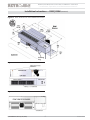
Figure 7 R10C
|
R10H chassis and installation
Figure 8 Weather Angles in factory location
Figure 9 Weather angles can be reversed to change o set
Figure 10 Direction of ba es and foam installation
Figure 11 Foam tape installation against wall sleeves
Replacement Packa
g
ed Terminal Air-Conditionin
g
/ Heat Pum
p
•
Installation, O
p
eration, and Maintenance Manual
•
P/N 240008034, Rev. E [5/16/2013] 13 Made in USA

INSTALLATION FOR NEW CONSTRUCTION
Installation Instructions — R20C
|
R20H
Installation
1. Verify the existing wall thickness — The distance from the
condenser coil to the outdoor louver varies with sleeve depth. Two
sets of air baffl es are included with each unit to accommodate
most installation requirements. Other air baffl e kits are available
from the factory (unique for applications). Know the wall sleeve
depth when ordering to ensure proper baffl e size.
2. Verify Weather Angle — Slide the unit into the wall sleeve.
If the supply duct on the cooling chassis does not line up with
the supply vent on the room cabinet, it is possible that factory
installed the weather angles on the top and the sides will have to
be reversed. This will allow approximately 1” of adjustment for
alignment with the supply vent when mounting the unit to the
wall sleeve (see Figure 13 and Figure 14). Slide the unit back in
the wall sleeve to verify proper fi t.
3. Install the ba es — Slide the unit back out of the wall
sleeve. Remove both sets of baffl es from the kit bag supplied
with unit. Install only one set of left and right side baffl es on
the condenser coil
by completing steps below
:
• Choose the proper fi tting baffl es for your application by
verifying selected baffl es come in contact with the outdoor
louver.
• Make sure the baffl es are directed inward toward the center
of coil (see Figure 15).
• Secure baffl es tightly into the existing holes of the condenser
coil using the screws provided.
NOTICE
The correct condenser air baffl es must be installed or perfor-
mance may be impaired.
4. Install the foam tape — Apply ¹⁄2” x ¹⁄2” open-cell foam
strips around supply air duct to ensure that all the conditioned
air is delivered into the room (see Figure 15). Failure to do
so results in recirculation of the conditioned air around the
cabinet causing the unit to short cycle and coil to freeze.
5. Install the foam tape —
apply 1” x 1” open-cell foam strips
to the weather angle to prevent outside air from entering
around the cooling chassis to the room from the sides and top
of the cabinet. Install between the wall sleeve and the chassis
(see Figure 16). It is imperative to have a solid air seal between
the wall sleeve and the chassis. Failure to do so will result in
air leakage from outdoor to indoor causing system problems
(example — coils freezing, short cycling, and constant run-
ning of unit). If there is a need for more foam than supplied
in kit, consult the factory.
6. Connecting the optional hydronic coil controls — If the
hydronic heat option has been ordered, then the hydronic coil
will need to be fi eld installed on the new unit. Hydronic coils
are not factory installed and need to be ordered. The coil with
the old unit can be located in the subbase, under the chas-
sis in a special attachment, or above the chassis in a special
attachment. It is necessary to know where the coil is to be
located and the physical size of the coil so the new coil can
be verifi ed if ordered for replacement. The new coil should
be installed in the same manner as the coil it is replacing.
• Remove the 2-position connector assembly from kit bag
supplied with unit (this will have 2 yellow wires attached).
• Connect this 2-position connector to the 2-position connec-
tion located on the bottom of the control box panel.
7. Connecting the accessory Aquastat — If the accessory
Aquastat has been ordered, then it will need to be fi eld in-
stalled.
• Remove the black jumper wire located on the bottom panel
of the control box (this is also terminated with a 2-position
connector).
• Cut the jumper wire in the middle and splice the Aquastat
to the jumper.
• Place the connector back into the original location. Refer to
the wiring diagram on the unit for details.
8. Secure the chassis — After ensuring that all seals are the
correct size and in the proper location and the correct baffl es
are attached to the condenser coil in the proper orientation,
slide the unit into the fi nal position and tighten any tie down
bolts or screws as necessary.
9. Hard-wired units — If the unit is hard wired, follow the
instructions on page 11 to verify existing wiring and overcur-
rent protection. Remove the line cord wires from the PTAC/
PTHP power entrance terminals. Route the power supply
wiring through a strain-relief bushing and connect leads to
the power entrance terminals. Secure the strain-relief clamp.
(If wiring is through conduit, insert the conduit through the
control box knockout and secure in place.) DO NOT turn on
power until completing instructions in "Final Inspection and
Startup" on page 24 .
10. DO NOT PLUG IN the line cord, if used. Follow instructions
in "Final Inspection and Startup" on page 24 .
Adjustable Weather Angle
Dimension "A" 8 5/8” 7 7/8” 9 11/16”
(1)
8”
(2)
Dimension "B" 9 1/2” 10 1/4” 8 7/16”
(1)
10 1/8”
(2)
Dimensions are calculated without foam gaskets.
(1) Standard position — Factory installed.
(2) Position for Climate Master 702 and 703.
R
ep
l
acement Pac
k
age
d
Termina
l
Air-Con
d
itioning / Heat Pum
p
•
Insta
ll
ation, O
p
eration, an
d
Maintenance Manua
l
•
The Right Fit for Comfort 14 P/N 240008034, Rev. E [5/16/2013]

Installation Instructions — R20C
|
R20H (continued)
Figure 12 R20C
|
R20H chassis and installation kit contents
Figure 13 Weather Angle in factory location
Figure 14 Weather Angle reversed to change o set
Figure 15 Direction of ba es and foam installation
Figure 16 Foam tape installation against wall sleeve
Replacement Packaged Terminal Air-Conditioning / Heat Pum
p
• Installation, O
p
eration, and Maintenance Manual
•
P/N 240008034, Rev. E [5/16/2013] 15 Made in USA

Installation Instructions — R35C
|
R35H
Installation
1. Verify the existing wall thickness — the distance from the
condenser coil to the outdoor louver varies with the sleeve
depth. Each chassis includes a ½" air baffl e to accommodate
the most common condenser coil to outdoor louver require-
ments. In addition, ECR International stocks an optional
condenser-side air baffl e kit for chassis installation in deeper
than standard walls.
2. Verify air supply alignment — slide the unit into the wall-
sleeve. The supply duct on the cooling chassis should line up
with the supply vent on the room cabinet.
3. Install the ba es — slide the unit back out of the wall
sleeve. Remove the baffl es from the kit bag supplied with
unit. Install the left and right side baffl es on the condenser
coil
by completing steps below
:
• Baffl es must come in contact with the outdoor louver.
• Make sure the baffl es are directed inward toward the center
of coil (see Figure 18).
• Secure baffl es tightly into the existing holes of the condenser
coil using the screws provided.
NOTICE
The correct condenser air baffl es must be installed or perfor-
mances may be impaired.
4. Install the foam tape — apply 1” x 1” open-cell foam
strips to the weather angle to ensure that all the conditioned
air is delivered into the room (see Figure 18). Failure to do
so results in recirculation of the conditioned air through the
cabinet causing the unit to short cycle, and coil to freeze.
NOTICE
The R35C/H is equipped with a bracket that allows the unit
to be adjusted up and down in the chassis of un-leveled wall
sleeves. Adjust leveler leg to desired height and tighten down
using bolts supplied on bracket (see Figure 19).
5. Connecting the hydronic coil — if the hydronic heat op-
tion has been ordered, then the hydronic coil will need to be
fi eld installed on the new unit. Hydronic coils are not factory
installed and need to be ordered. The coil with the old unit
can be located in the subbase, under the chassis in a special
attachment, or above the chassis in a special attachment. It
is necessary to know where the coil is to be located and the
physical size of the coil so the new coil can be verifi ed if
ordered for replacement. The new coil should be installed in
the same manner as the coil it is replacing.
• Remove the 2-position connector assembly from kit bag
supplied with unit (this will have 2 yellow wires attached).
• Connect this 2-position connector to the 2-position connec-
tion located on the bottom of the control box panel.
6. Connecting the accessory Aquastat —
if the accessory
Aquastat has been ordered then it will need to be fi eld installed.
• Remove the black jumper wire located on the bottom panel
of the control box (this is also terminated with a 2-position
connector).
• Cut the jumper wire in the middle and splice the Aquastat
to the jumper.
• Place the connector back into original location. Refer to the
wiring diagram on the unit for details.
7. Secure the chassis — after ensuring that all seals are the
correct size and in the proper location and the correct baffl es
are attached to the condenser coil and in the proper orienta-
tion, slide the unit into fi nal position and tighten any tie down
bolts or screws as necessary.
8. Hard-wired units — If the unit is hard wired, follow the
instructions on page 11 to verify existing wiring and overcur-
rent protection. Remove the line cord wires from the PTAC/
PTHP power entrance terminals. Route the power supply
wiring through a strain-relief bushing and connect leads to
the power entrance terminals. Secure the strain-relief clamp.
(If wiring is through conduit, insert the conduit through the
control box knockout and secure in place.) DO NOT turn on
power until completing instructions in "Final Inspection and
Startup" on page 24 .
9. DO NOT PLUG IN the line cord, if used. Follow instructions
in "Final Inspection and Startup" on page 24 .
R
ep
l
acement Pac
k
age
d
Termina
l
Air-Con
d
itioning / Heat Pum
p
•
Insta
ll
ation, O
p
eration, an
d
Maintenance Manua
l
•
The Right Fit for Comfort 16 P/N 240008034, Rev. E [5/16/2013]

Installation Instructions — R35C
|
R35H (continued)
Install 2" x ¹⁄" foam tape
Leveling
Leg
Figure 17 R35C
|
R35H chassis and installation kit contents
Figure 18 Direction of ba es and foam installation
Figure 19 Front view of chassis
•
Installation, O
p
eration, and Maintenance Manual
•
P/N 240008034, Rev. E [5/16/2013] 17 Made in USA

Installation Instructions — R45C
|
R45H
Installation
1. Verify the existing wall thickness — The distance from the
condenser coil to the outdoor louver varies with wall sleeve
depth. Two sets of air baffl es are included with each unit to
accommodate most installation requirements. Other air baffl e
kits are available from the factory (unique for applications).
Have the wall sleeve depth ready when ordering to ensure
proper baffl e size.
2. Verify Weather Angle — Slide the unit into the wall sleeve.
If the supply duct on the cooling chassis does not line up with
the supply vent on the room cabinet, it is possible that factory
installed the weather angle on the top and the sides will have
to be reversed. This will allow approximately 1” of adjust-
ment for alignment with the supply vent when mounting the
unit to the wall sleeve (see Figure 21 and Figure 22). Slide
the unit back in the wall sleeve to verify proper fi t.
3. Install the ba es — Slide the unit back out of the wall
sleeve. Remove both sets of baffl es from the kit bag supplied
with unit. Install only one set of left and right side baffl es on
the condenser coil
by completing steps below
:
• Choose the proper fi tting baffl es for your application by
verifying selected baffl es come in contact with the outdoor
louver.
• Make sure the baffl es are directed inward toward the center
of coil (see Figure 23).
• Secure baffl es tightly into the existing holes of the condenser
coil using the screws provided.
NOTICE
The correct condenser air baffl es must be installed or perfor-
mances may be impaired.
4. Install the foam tape — Apply ¹⁄2” x ¹⁄2” open-cell foam
strips around supply air duct to ensure that all the conditioned
air is delivered into the room (see Figure 23). Failure to do so
results in recirculation of the conditioned air through the cabi-
net causing the unit cabinet to short cycle and coils to freeze.
5. Install the foam tape — Apply
1” x 1” open-cell foam
strips to the weather angle to prevent outside air from enter-
ing around the chassis to the room from the sides and top of
the cabinet. Install the strips between the wall sleeve and the
chassis (see Figure 23). It is imperative to have a solid air
seal between the wall sleeve and the chassis. Failure to do
so will result in air leakage from outdoor to indoor causing
system problems (example — coils freezing, short cycling, and
constant running of unit). If there is a need for more foam
than supplied in kit, consult the factory W/A .
6. Foam tape installation hydronic coil buy controls — If the
hydronic heat option has been ordered, then the hydronic coil
will need to be fi eld installed on the new unit. The coil with
the old unit can be located in the subbase, under the chassis in
a special attachment, or above the chassis in a special attach-
ment. It is necessary to know where the coil is to be located
and the physical size of the coil so the new coil can be verifi ed
if ordered for replacement. The new coil should be installed
in the same manner as the coil it is replacing. Hydronic coils
are not factory installed and need to be ordered.
• Remove the 2-position connector assembly from kit bag
supplied with unit (this will have 2 yellow wires attached).
• Connect this 2-position connector to the 2-position connec-
tion located on the bottom of the control box panel.
7. Connecting the accessory Aquastat — If the accessory
Aquastat has been ordered then it will need to be fi eld in-
stalled.
• Remove the black jumper wire located on the bottom panel
of the control box (this is also terminated with a 2-position
connector).
• Cut the jumper wire in the middle and splice the Aquastat
to the jumper.
• Place the connector back into original location. Refer to the
wiring diagram on the unit for details.
8. Secure the chassis — After ensuring that all seals are the
correct size and in the proper location, and the correct baffl es
are attached to the condenser coil in the proper orientation,
slide the unit into fi nal position and tighten any tie down bolts
or screws as necessary.
9. Hard-wired units — If the unit is hard wired, follow the
instructions on page 11 to verify existing wiring and overcur-
rent protection. Remove the line cord wires from the PTAC/
PTHP power entrance terminals. Route the power supply
wiring through a strain-relief bushing and connect leads to
the power entrance terminals. Secure the strain-relief clamp.
(If wiring is through conduit, insert the conduit through the
control box knockout and secure in place.) DO NOT turn on
power until completing instructions in "Final Inspection and
Startup" on page 24 .
10. DO NOT PLUG IN the line cord, if used. Follow instructions
in "Final Inspection and Startup" on page 24 .
•
Insta
ll
ation, O
p
eration, an
d
Maintenance Manua
l
•
The Right Fit for Comfort 18 P/N 240008034, Rev. E [5/16/2013]

Installation Instructions — R45C
|
R45H CONTROLS (continued)
Figure 20 R45C
|
R45H chassis and installation kit contents
Figure 21 Weather Angle in factory location
Figure 22 Weather Angles reversed to gain extra distance
Figure 23 Direction of ba es and foam installation
Replacement Packa
g
ed Terminal Air-Conditionin
g
/ Heat Pum
p
•
Installation, O
p
eration, and Maintenance Manual
•
P/N 240008034, Rev. E [5/16/2013] 19 Made in USA

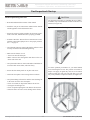
Installation Instructions — R90C
|
R90H
Installation
1. Verify the existing wall thickness — the distance from the
condenser coil to the outdoor louver varies with the sleeve
depth. Each chassis includes standard air baffl es to accom-
modate the most common condenser coil to outdoor louver
requirements. In addition, we stock an optional condenser-
side air baffl e kit for chassis installation in deeper than
standard walls.
NOTICE
The R90C
|
R90H chassis is 18
” deep for 9, 12, 15 Btuh
models. The standard depth for the 18 Btuh is 24", However
EMI can supply it for an
18
” chassis on demand (consult
factory).
2. Install duct collar and slide-duct — remove duct collar
and slide-duct from packaging. Affi x ¹⁄4” x ¾” foam tape to
the bottom fl anges of the duct collar (this serves as a gasket
between the collar and the unit). Securely fasten duct collar
over discharge openining with screws provided. Insert slide-
duct into duct collar (see Figure 24).
3. Verify air supply alignment — slide the unit into the wall-
sleeve. The supply duct on the cooling chassis should line
up with the supply vent on the room cabinet. The weather
angles should need no adjustment.
4. Install the ba es — slide the unit back out of the wall
sleeve. Remove the baffl es from the kit bag supplied with
unit. Install the left and right side baffl es on the condenser
coil
by completing steps below
:
• Baffl es must come in contact with the outdoor louver.
• Make sure the baffl es are directed inward toward the center
of coil (see Figure 25).
• Secure baffl es tightly into the existing holes of the condenser
coil using the screws provided.
NOTICE
The correct condenser air baffl es must be installed or perfor-
mances may be impaired.
5. Install the foam tape — apply ¹⁄2” x ¹⁄2” open-cell foam
strips around the top of the supply air duct collar to ensure that
all the conditioned air is delivered into the room (see Figure
25). Failure to do so results in recirculation of the conditioned
air through the cabinet unit causing the unit to short cycle.
6. Install the foam tape — Apply
1” x 1” open-cell foam strips
to the wether angle this prevents outside air from entering
around the chassis to the room from the sides and top of the
cabinet. Install the strips to weather strip between the wall
sleeve and the cooling chassis (see Figure 26). It is imperative
to have a solid air seal between the wall sleeve and the chas-
sis. Failure to do so will result in air leakage from outdoor to
indoor causing system problems (example — coils freezing,
short cycling, and constant running of unit). If there is a
need for more foam than supplied in kit, consult the factory.
7. Connecting the optional hydronic coil — if the hydronic
heat option has been ordered, then the hydronic coil will need
to be fi eld installed on the new unit. The coil with the old unit
can be located in the subbase, under the chassis in a special
attachment, or above the chassis in a special attachment. It
is necessary to know where the coil is to be located and the
physical size of the coil so the new coil can be verifi ed if
ordered for replacement. The new coil should be installed in
the same manner as the coil it is replacing.
• Remove the 2-position connector assembly from kit bag
supplied with unit (this will have 2 yellow wires attached).
• Connect this 2-position connector to the 2-position connec-
tion located on the bottom of the control box panel.
8. Connecting the accessory Aquastat — if the accessory
Aquastat has been ordered then it will need to be fi eld in-
stalled.
• Remove the black jumper wire located on the bottom panel
of the control box (this is also terminated with a 2-position
connector).
• Cut the jumper wire in the middle and splice the Aquastat
to the jumper.
• Place the connector back into original location. Refer to the
wiring diagram on the unit for details.
9. Secure the chassis — after ensuring that all seals are the
correct size and in the proper location and the correct baffl es
are attached to the condenser coil and in the proper orienta-
tion, slide the unit into fi nal position and tighten any tie down
bolts or screws as necessary.
10. Install the control section — Remove the front cover of
the unit. In a unit mount installation, take the thermal bulb
from the control section and run the capillary tube bulb along
the unit to the blower section. (There will be no thermostat
bulb if a remote thermostat option is used.) While looking at
the sides of the blower housing, there are two clips that will
support the thermal bulb. Remove the screws (keep screws
to reattach) that hold these clips and slide the thermal bulb
into the clips. Fasten the clips back into place, making sure
to not kink the bulb. After the thermostat is in place, mount
the control box in the cabinet in the same location as the old
control box ,reinstall the front cover of the unit and fi nish
the installation.
11. Hard-wired units — If the unit is hard wired, follow the
instructions on page 11 to verify existing wiring and overcur-
rent protection. Hard wire the line voltage to control box and
plug cooling chassis line cord into control box receptacle and
molex plugs. Remove the line cord wires from the PTAC/
PTHP power entrance terminals. Route the power supply
wiring through a strain-relief bushing and connect leads to
the power entrance terminals. Secure the strain-relief clamp.
(If wiring is through conduit, insert the conduit through the
control box knockout and secure in place.) DO NOT turn on
power until completing instructions in "Final Inspection and
Startup" on page 24 .
12. DO NOT PLUG IN the line cord, if used. Follow instructions
in "Final Inspection and Startup" on page 24 .
R
ep
l
acement Pac
k
age
d
Termina
l
Air-Con
d
itioning / Heat Pum
p
•
Insta
ll
ation, O
p
eration, an
d
Maintenance Manua
l
•
The Right Fit for Comfort 20 P/N 240008034, Rev. E [5/16/2013]
Page is loading ...
Page is loading ...
Page is loading ...
Page is loading ...
Page is loading ...
Page is loading ...
Page is loading ...
Page is loading ...
Page is loading ...
Page is loading ...
Page is loading ...
Page is loading ...
Page is loading ...
Page is loading ...
Page is loading ...
Page is loading ...
Page is loading ...
Page is loading ...
Page is loading ...
Page is loading ...
-
 1
1
-
 2
2
-
 3
3
-
 4
4
-
 5
5
-
 6
6
-
 7
7
-
 8
8
-
 9
9
-
 10
10
-
 11
11
-
 12
12
-
 13
13
-
 14
14
-
 15
15
-
 16
16
-
 17
17
-
 18
18
-
 19
19
-
 20
20
-
 21
21
-
 22
22
-
 23
23
-
 24
24
-
 25
25
-
 26
26
-
 27
27
-
 28
28
-
 29
29
-
 30
30
-
 31
31
-
 32
32
-
 33
33
-
 34
34
-
 35
35
-
 36
36
-
 37
37
-
 38
38
-
 39
39
-
 40
40


EMI R10/R20/R35/R45/R80/R90 Dual Motor PTAC Installation & Operation Manual
- Type
- Installation & Operation Manual
Ask a question and I''ll find the answer in the document
Finding information in a document is now easier with AI
Related papers
-
EMI R10/R20/R35/R45/R80/R90 Installation & Operation Manual
-
-
-
-
-
-
-
-
-
Other documents
-
Steba 39.01.00 Datasheet
-
Friedrich WCT12A30A Installation guide
-
 RiteTemp 6008 Operating instructions
-
COMFORT-AIRE PTHP07A230A-CY Owner's manual
-
Mars PTAC G-Series Operating instructions
-
COMFORT-AIRE PTHP12A130A-CY Owner's manual
-
SoleusAir HCC-C15HP-A User manual
-
-
ClimateMaster PTAC Install Manual
-
 Oxbox JAYLOAM001 User manual

