Page is loading ...

1
Owner’s Manual
Warranty
Registration:
register online today for a
chance to win a FREE Tripp Lite
product—www.tripplite.com/warranty
NetDirector Cat5 IP
KVM Switches
Models:
B064-016-04-IP, B064-016-02-IP, B064-032-02-IP, B064-032-04-IP
FCC Information
This is an FCC Class A product. In a domestic environment this product may cause radio interference in which case the user may be required to
take adequate measures.
This equipment has been tested and found to comply within the limits of a Class A digital device, pursuant to Part 15 of the FCC Rules. These
limits are designed to provide reasonable protection against harmful interference when the equipment is operated in a commercial environment.
This equipment generates, uses and can radiate radio frequency energy and, if not installed and used in accordance with the instruction manual,
may cause harmful interference to radio communications. Operation of this equipment in a residential area is likely to cause harmful interference
in which case the user will be required to correct the interference at his own expense.
RoHS
This product is RoHS compliant.
Package Contents
This package consists of:
(1) B064-016-02-IP, B064-016-04-IP, B064-
032-02-IP or B064-032-04-IP KVM
Switch
(1) USB – PS/2 Console Cable Kit
(1) RJ45 to DB9 Adapter
(1) Grounding Wire
(1) Power Cord
(1) Rack Mount Kit
(1) Foot Pad Set (4 pcs.)
(1) CD (including Owner’s Manual and
Device Files)
Tripp Lite World Headquarters
1111 W. 35th Street, Chicago, IL 60609 USA
(773) 869-1234 • www.tripplite.com
Note: Follow these instructions to ensure proper operation and prevent damage to this device and its connected equipment.
Copyright © 2008 Tripp Lite. All rights reserved. All trademarks are the property of their respective owners.

2
Table of Contents
Table of Contents ........................................2
Introduction ............................................4
Overview ...............................................4
Features ................................................4
Remote Console Computers ................................5
Connected Computer/Servers ...............................5
Video ..................................................5
Server Interface Units (SIUs)................................5
Operating Systems ........................................5
Browsers................................................6
Components .............................................6
Hardware Setup .........................................8
Before You Begin .........................................8
General Safety Instructions .................................8
Stacking ................................................9
Rack Mounting...........................................9
Single Station Installation ..................................9
Two Stage Installations ...................................10
Hardware Setup .........................................11
Hot Plugging ...........................................11
Powering Off and Restarting ...............................11
Port ID Numbering ......................................11
Super Administrator Setup ...............................12
First Time Setup.........................................12
Network Setup - IP Address Determination....................12
NIC Settings............................................13
Changing the Super Administrator Login .....................14
Moving On.............................................14
Accessing the B064-Series KVM Switch ....................15
Local Console Login .....................................15
Browser Login . . . . . . . . . . . . . . . . . . . . . . . . . . . . . . . . . . . . . . . . . .15
AP Windows Client Login .................................16
The Connection Screen ...................................16
The File Menu ..........................................16
The Tools Menu .........................................17
AP Java Client Login .....................................17
The OSD Main Page ....................................18
The OSD Main Page .....................................18
OSD Icon Bar...........................................18
The Control Panel .......................................19
Hotkey Setup ...........................................19
Video Options ..........................................20
Gamma Adjustment ......................................21
The Message Board ......................................22
The Button Bar..........................................22
User List Panel..........................................22
Compose Panel..........................................22
Message Display Panel ...................................22
The On-Screen Keyboard..................................23
Mouse Pointer Type ......................................23
Mouse Sync Mode .......................................23
Manual Mouse Synchronization ............................23
Port Access ............................................25
The Port Selection Panel ..................................25
The Port Selection List....................................26
Port Configuration .......................................26
Port Naming............................................26
Port Properties ..........................................27
Scan ..................................................28
Panel Array Mode .......................................28
Filter..................................................28
The Information and Configuration Notebook .................28
History ................................................28
Favorites...............................................29
Adding a Favorite........................................29
Modifying a Favorite .....................................29
User Settings ...........................................30
Log ...................................................30
Filter..................................................31
Sessions ...............................................31
Access ................................................31
The Main Panel – Switches ................................32
The Main Panel – Computers/Servers ........................32
The Status Panel.........................................33
The Properties Panel .....................................33
User Management ......................................34
The User Management Main Page...........................34
Users - Adding Users .....................................34
Users – Modifying Users ..................................36
Users – Deleting Users....................................36
Groups ................................................36
Groups – Creating Groups .................................36
Groups – Modifying Groups ...............................37
Groups – Deleting Groups .................................37
Assigning Users to Groups ................................37
Assigning Users to a Group via the User’s Notebook ............38
Removing Users From a Group via the User’s Notebook .........38
Assigning Users to a Group via the Group’s Notebook...........39
Removing Users From a Group via the Group’s Notebook........39
Device Assignment ......................................40
Assigning Device Permissions..............................40
Filters .................................................40
Device Management.....................................41
The Main Page ..........................................41
General................................................41
Network ...............................................41
IP Installer .............................................42
NIC Settings............................................42
Redundant NIC .........................................42
IP Address .............................................42
DNS Server ............................................42
Network Transfer Rate....................................42
Security ...............................................43
Filtering ...............................................43
IP Filtering .............................................43
MAC Filtering ..........................................44
Customization ..........................................44
Login Failures ..........................................44
Working Mode ..........................................44
Miscellaneous ..........................................45
Service ................................................46
Access Ports............................................46
Log Server .............................................46
ANMS ................................................46

3
Table of Contents
RADIUS Settings........................................47
LDAP / LDAPS Authentication and Authorization Settings .......47
LDAP Configuration — Active Directory .....................47
Create a Start Menu Shortcut Entry..........................48
Extend and Update the Active Directory Schema ...............48
OpenLDAP Server .......................................51
OpenLDAP Server Installation .............................51
OpenLDAP Server Configuration ...........................52
Starting the OpenLDAP Server .............................52
Customizing the OpenLDAP Schema ........................52
DIT Creation ...........................................53
Date/Time..............................................54
OOBC ................................................54
Maintenance ...........................................56
The Main Screen ........................................56
Firmware File...........................................56
Options................................................56
The Main Panel .........................................56
Upgrading the Firmware ..................................57
B064-Series KVM switch Firmware Upgrade Recovery..........58
Server Interface Unit Firmware Upgrade Recovery .............58
Download .............................................58
Port Operation . . . . . . . . . . . . . . . . . . . . . . . . . . . . . . . . . . . . . . . . .59
The OSD Toolbar ........................................59
Panel Array Mode .......................................60
Panel Array Toolbar ......................................60
Multiuser Operation......................................61
Auto Scanning ..........................................61
Setting the Scan Interval ..................................61
Invoking Auto Scan ......................................61
Pausing Auto Scan .......................................61
Exiting Auto Scan .......................................61
Skip Mode .............................................62
The Log Server.........................................63
Installation .............................................63
Starting Up.............................................63
The Menu Bar ..........................................63
Configure ..............................................64
Edit...................................................64
Delete .................................................64
Events.................................................64
Search.................................................65
Maintenance............................................65
Options................................................66
Help ..................................................66
Contents ...............................................66
About Log Server........................................66
The Log Server Main Screen — Overview ....................66
The Log Server Main Screen — Overview ....................66
The Log Server..........................................67
The List Panel ..........................................67
The Event Panel .........................................67
Appendix..............................................68
General Operation Troubleshooting..........................68
Administration Troubleshooting ............................68
AP Windows Client Troubleshooting ........................68
Panel Array Mode Troubleshooting ..........................69
AP Java Client Troubleshooting ............................69
The Log Server Troubleshooting ............................69
Sun Systems Troubleshooting ..............................69
Specifications ..........................................70
OSD Factory Default Settings . . . . . . . . . . . . . . . . . . . . . . . . . . . . . .70
4
Introduction
Overview
Features
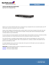
The NetDirector Matrix KVM Switch with Multi-User IP Access allows both local and remote operators to monitor and access multiple
computers from a single console. For example, a single B064-032-04-IP can control up to 32 computers.
The switches are differentiated according to the number of users they support and the number of KVM ports they provide – as shown in the table
below:
Model User Support KVM Ports
B064-016-02-IP 2-User 16
B064-016-04-IP 4-User 16
B064-032-02-IP 2-User 32
B064-032-04-IP 4-User 32
Each user port allows for a separate user session, so that up to three
(B064-016-02-IP and B064-032-02-IP) or five (B064-016-04-IP and
B064-032-04-IP) users can access the KVM switch at the same time.
• Directlyconnectupto16(B064-016-04-IPorB064-016-02-IP)or32(B064-032-02-IPorB064-032-04-IP)computers/servers
• Addadditionalcomputers/serversinatwo-levelcascadeinstallation
• Two10/100/1000MbpsnetworkconnectionsforredundantLANortwoIPoperation
• Supportsupto2(B064-032-02-IPorB064-016-02-IP)or4(B064-016-04-IPorB064-032-04-IP)remotesessions
• 1Localand2RemoteUserscansimultaneouslyaccesstheB064-032-02-IPorB064-016-02-IP
• 1Localand4RemoteUserscansimultaneouslyaccesstheB064-016-04-IPorB064-032-04-IP
• Upto32userscanremotelyshareoneuserport
• Createupto64useraccounts
• Multi-levelauthentication:superadministrator;administrator;user
• Advancedsecurityfeaturesincludepasswordprotectionandadvancedencryptiontechnologies–1024bitRSA;56bitDES;256bitAES;and
128 bit SSL
• RJ45connectorsandCat5ecableallowforamoreefcientinstallation
• Web-basedJavaClientallowstheswitchtobeaccessedfromaninternetbrowser
• Browseraccesscanbedisabled–WindowsandJavaGUIAPprogramsprovidedfornon-browserconnectivity
• GraphicalOSDandtoolbarsprovideconvenient,userfriendlyoperation
• Full-screengraphicalOSDforthelocalconsole
• Full-screenorsizableremotedesktopwindow;infull-screenmodetheremotedesktopdisplayscalestouser’smonitordisplaysize
• PanelArrayMode–viewupto32portsatthesametime
• Highvideoresolution:upto1600x1200@60Hz–32bitforthelocalconsole;upto1600x1200@60Hzforremotesessions
• Multi-languagesupport
• Software(On-screen)keyboard
• UltraSyncforUSBmice–localandremotemousemovementarethesame–noneedtoconstantlyre-syncthetwomovements
• Windows-basedLogServer
• SupportsallmajorserverplatformsandVT100basedserialdevices
• Supportsmulti-platformserverenvironments:PS/2andUSB
• Supports10Base-T,100Base-T,1000Base-T,Auto-Sense,TCP/IP,HTTP,DNS,DHCP,UDP,ARP,Ping
• Remoteauthenticationsupport:RADIUS,LDAP,LDAPS,andActiveDirectory
• Flashupgradeablermwareoverthenetwork
5
Introduction
Remote Console Computers
Connected Computer/Servers
Video
Server Interface Units (SIUs)
Operating Systems
• Browsersmustsupport128-bitSSLencryption.
• Forthebrowser-basedJavaAppletandAPJavaClient,thelatestversionofSun’sJavaRuntimeEnvironment(JRE)V6,Update3orhigher
must be installed.
• FortheLogServer,youmusthavetheMicrosoftJetOLEDB4.0orhigherdriverinstalled.
• ForbestresultswerecommendthatthecomputersusedtoaccesstheswitchhaveatleastaPentiumIII,1GHzprocessor,withtheirscreen
resolution set to 1024 x 768.
• Forbestresults,anetworktransferspeedofatleast128kbpsisrecommended.
Computers/servers to be connected to the B064-Series KVM Switch must have the following:
• VGA,SVGAorMultisyncport
• ForUSBServerInterfaceUnitConnections:TypeAUSBportandUSBhostcontroller
• ForPS/2ServerInterfaceUnitConnections:6-pinmini-DINkeyboardandmouseports
Only the following non-interlaced video signals are supported:
Cat5e/6 cable is required to connect the B064-Series KVM Switches
to one of the Server Interface Units (SIUs). The following SIUs are
required for use with the B064 Series KVM Switch:
Supported operating systems for computer/servers that connect to the
B064-Series KVM switches are shown in the table at right:
Supported operating systems for users that remotely log into the
B064-Series KVM Switches include Windows 2000 and higher, and
those capable of running Sun’s Java Runtime Environment (JRE) 6,
Update 3, or higher.
Resolution Refresh Rates
640 x 480 60, 72, 75, 85, 90, 100, 120
720 x 400 70
800 x 600 56, 60, 72, 75, 85, 90, 100, 120
1024 x 768 60, 70, 75, 85, 90, 100
1152 x 864 60, 70, 75, 85
1280 x 1024 60, 70, 75, 85
1600 x 1200 60
Function
Server
Interface unit
Connect to a computer/server with PS/2 Ports B054-001-PS2
Connect to a computer/server with USB ports B054-001-USB
OS Version
Windows 2000 and higher
Linux Red Hat 7.1 and higher
Linux Fedora Core 2 and higher
Linux SuSE 9.0 and higher
Linux Mandriva 9.0 and higher
UNIX AIX 4.3 and higher
UNIX FreeBSD 4.2 and higher
UNIX Sun Solaris 8 and higher
Novell Netware 5.0 and higher
Mac OS 9 and higher
DOS 6.2 and higher
1
4 5 6
2 3
6
Introduction
Browsers
Components
Supported browsers for users that remotely log into the B064-Series
KVM Switches include the following:
Browser Version
Internet Explorer 6 and higher
Firefox 1.5 and higher
Mozilla 1.7 and higher
Safari 2.0 and higher
Opera 9.0 and higher
Netscape 8.1 and higher
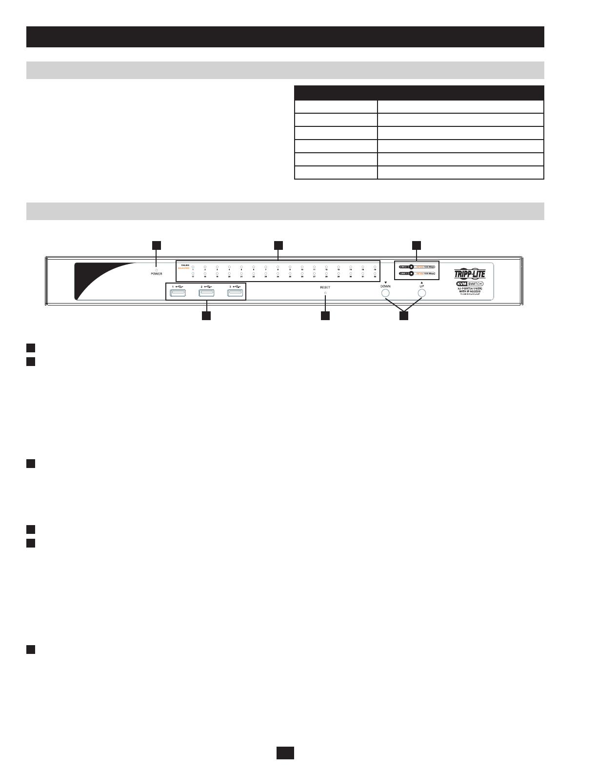
Front View
No. Component Description
1
Power LED Illuminates when the KVM switch is powered on
2
Port LEDs The Port LEDs will illuminate different colors depending on the status of the corresponding port:
Green – The Port LED will illuminate Green when the corresponding port is connected and powered-on
Red – The Port LED will illuminate Red when the corresponding port is selected as having the KVMs focus,
but is either not connected to a computer/server or is connected to a computer/server that is not powered-on
Orange – The Port LED will illuminate Orange when the corresponding port is connected, powered-on and
selected as having the KVMs focus
Note: The LEDs are steady under normal conditions, but will flash at half second intervals when the
corresponding port is being accessed under Auto Scan Mode or Skip Mode.
3
LAN LEDs The Primary (Link 1) and Secondary (Link 2) LAN LEDs will illuminate different colors depending upon the
network transfer rate:
Red – The LAN LEDs will illuminate Red at speeds of 10 Mbps
Orange – The LAN LEDs will illuminate Orange at speeds of 100 Mbps
Green - The LAN LEDs will illuminate Green at speeds of 1000 Mbps
4
USB Ports Additional USB peripherals can be plugged into these ports (Keyboard, Mouse, etc.)
5
Reset Switch
Note: This switch is recessed and must be pushed with a thin object, such as the end of a paper clip or a
ballpoint pen.
•PressingandreleasingtheResetButtonwhentheKVMswitchisrunningperformsasystemreset.
•PressingandholdingtheResetButtoninformorethanthreesecondswhentheKVMswitchisrunningresets
the switch configuration to the factory default settings. Note: This does not clear User Account information.
See Clear Login Information, page xx, for instructions on clearing user account information.
•PressingandholdingtheResetButtoninwhilepoweringontheswitchwillrestoretheKVMswitchtoits
original firmware in the event of a firmware upgrade failure. Note: This operation should only be performed
in the event of a firmware upgrade failure that results in the device becoming inoperable.
6
Port Switching Buttons •PressthePort Down button to switch from the current port to the previous port on the installation.
•PressthePort Up button to switch from the current port to the next port on the installation.
Note: The figure shows the front panel of a B064-032-04-IP. The B064-032-02-IP, B064-016-02-IP and B064-016-04-IP contain all the same
front-panel features as the B064-032-04-IP, except the B064-016-04-IP and B064-016-02-IP come with 16 ports instead of 32.
1 2 3
4 6 7 85
7
Introduction
Components (continued)
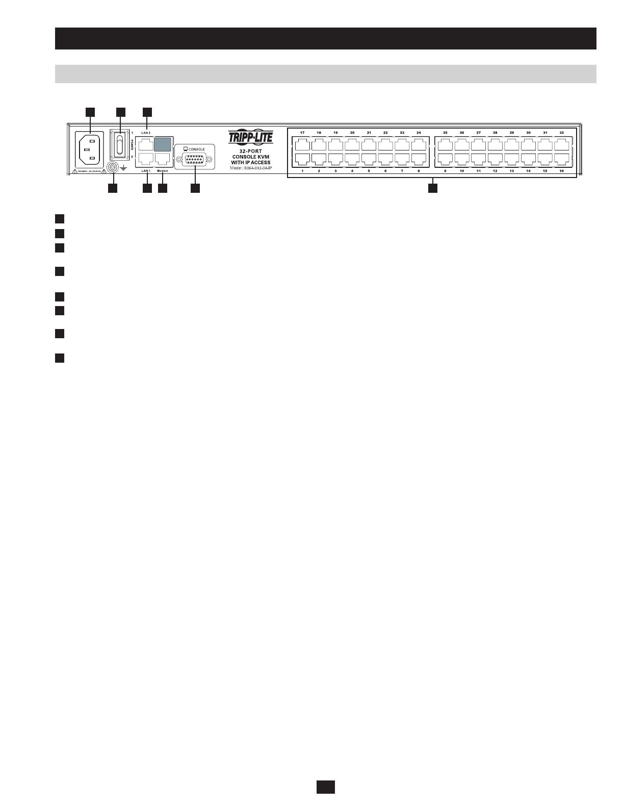
Rear View
No. Component Description
1
Power Socket The included power cord connects here.
2
Power Switch Press to turn the KVM switch On/Off.
3
Secondary LAN Port
(LAN 2)
The cable that connects the KVM switch to the backup network plugs in here.
4
Primary LAN Port
(LAN 1)
The cable that connects the KVM switch to the primary network plugs in here.
5
Grounding Terminal Connect the included grounding wire to this terminal to ground the KVM switch.
6
Modem Port An optional dial-in connection is available for use in the event the KVM switch is not available over the Primary
or Secondary networks.
7
Local Console Port The included USB – PS/2 Console Cable Kit plugs in here. You can connect a local console with either a USB or
PS/2 Keyboard and Mouse.
8
Server Ports Cat5e/6 cable connects between these ports and the SIUs to connect computer/servers to the KVM switch.
Note: The figure above shows the rear panel of a B064-032-04-IP or B064-032-02-IP. The B064-016-04-IP and B064-016-02-IP differ in that
it only has a single block of 16 KVM ports.

8
Hardware Setup
Before You Begin
General Safety Instructions
• Readalloftheseinstructions.Savethemforfuturereference.
• Followallwarningsandinstructionsmarkedonthedevice.
• Use of this equipment in life support applications where failure of this equipment can reasonably be expected to cause the failure of the life
support equipment or to significantly affect its safety or effectiveness is not recommended. Do not use this equipment in the presence of a
flammable anesthetic mixture with air, oxygen or nitrous oxide.
• ThisdeviceisdesignedforITPowerDistributionsystemswithupto230Vphase-to-phasevoltage.
• Donotplacethedeviceonanyunstablesurface(cart,stand,table,etc.).Ifthedevicefalls,seriousdamagewillresult.
• Donotusethedevicenearwater.
• Donotplacethedevicenear,orover,radiatorsorheatregisters.
• Thedevicecabinetisprovidedwithslotsandopeningstoallowforadequateventilation.Toensurereliableoperation,andtoprotectagainst
overheating, these openings must never be blocked or covered.
• Thedeviceshouldneverbeplacedonasoftsurface(bed,sofa,rug,etc.),asthiswillblockitsventilationopenings.Likewise,thedeviceshould
not be placed in a built in enclosure unless adequate ventilation has been provided.
• Neverspillliquidofanykindonthedevice.
• Unplugthedevicefromthewalloutletbeforecleaning.Donotuseliquidoraerosolcleaners.Useadampclothforcleaning.
• Thedeviceshouldbeoperatedfromthetypeofpowersourceindicatedonthemarkinglabel.Ifyouarenotsureofthetypeofpoweravailable,
consult your dealer or local power company.
• Topreventdamagetoyourinstallationitisimportantthatalldevicesareproperlygrounded.
• Thedeviceisequippedwitha3-wiregroundingtypeplug.Thisisasafetyfeature.Ifyouareunabletoinserttheplugintotheoutlet,contact
your electrician to replace your obsolete outlet. Do not attempt to defeat the purpose of the grounding-type plug. Always follow your local/
national wiring codes.
• Donotallowanythingtorestonthepowercordorcables.Routethepowercordandcablessothattheycannotbesteppedonortrippedover.
• Ifanextensioncordisusedwiththisdevicemakesurethatthetotalampereratingofallproductsusedonthiscorddoesnotexceedthe
extension cord ampere rating. Make sure that the total of all products plugged into the wall outlet does not exceed 15 amperes.
• Tohelpprotectyoursystemfromsudden,transientincreasesanddecreasesinelectricalpower,itisrecommendedthatyouplugyourdevices
into a Tripp Lite surge suppressor, line conditioner, or uninterruptible power supply (UPS).
• Positionsystemcablesandpowercablescarefullytoensurethatnothingrestsonanycables.
• Whenconnectingordisconnectingpowertohot-pluggablepowersupplies,observethefollowingguidelines:
• Installthepowersupplybeforeconnectingthepowercabletothepowersupply.
• Unplugthepowercablebeforeremovingthepowersupply.
• Ifthesystemhasmultiplesourcesofpower,disconnectpowerfromthesystembyunpluggingallpowercablesfromthepowersupplies.
• Neverpushobjectsofanykindintoorthroughcabinetslots.Theymaytouchdangerousvoltagepointsorshortoutpartsresultinginarisk
of fire or electrical shock.
• Donotattempttoservicethedeviceyourself.Referallservicingtoqualiedservicepersonnel.
• Ifthefollowingconditionsoccur,unplugthedevicefromthewalloutletandbringittoqualiedservicepersonnelforrepair:
• Thepowercordorplughasbecomedamagedorfrayed.
• Liquidhasbeenspilledintothedevice.
• Thedevicehasbeenexposedtorainorwater.
• Thedevicehasbeendropped,orthecabinethasbeendamaged.
• Thedeviceexhibitsadistinctchangeinperformance,indicatinganeedforservice.
• Thedevicedoesnotoperatenormallywhentheoperatinginstructionsarefollowed.
• Onlyadjustthosecontrolsthatarecoveredintheoperatinginstructions.Improperadjustmentofothercontrolsmayresultindamagethatwill
require extensive work by a qualified technician to repair.
• DonotconnecttheRJ11connectormarked“UPGRADE”toapublictelecommunicationnetwork.

Use the M3x8 Phillips head hex screws
provided with the rack mount kit
Use user supplied
hardware to attach
to the rack
9
Hardware Setup
Rack Mounting Safety Instructions
• Beforeworkingontherack,makesurethatthestabilizersaresecuredtotherack,extendedtotheoor,andthatthefullweightoftherack
rests on the floor. Install front and side stabilizers on a single rack or front stabilizers for joined multiple racks before working on the rack.
• Alwaysloadtherackfromthebottomup,andloadtheheaviestitemintherackrst.
• Makesurethattherackislevelandstablebeforeextendingadevicefromtherack.
• Usecautionwhenpressingthedevicerailreleaselatchesandslidingadeviceintooroutofarack;thesliderailscanpinchyourngers.
• Afteradeviceisinsertedintotherack,carefullyextendtherailintoalockingposition,andthenslidethedeviceintotherack.
• DonotoverloadtheACsupplybranchcircuitthatprovidespowertotherack.Thetotalrackloadshouldnotexceed80percentofthebranch
circuit rating.
• Makesurethatallequipmentusedontherack,includingpowerstripsandotherelectricalconnectors,isproperlygrounded.
• Ensurethatproperairowisprovidedtodevicesintherack.
• Ensurethattheoperatingambienttemperatureoftherackenvironmentdoesnotexceedthemaximumambienttemperaturespeciedforthe
equipment by the manufacturer
• Donotsteponorstandonanydevicewhenservicingotherdevicesinarack.
The KVM switch can be placed on any appropriate level surface that can safely support its weight plus the weight of its attached cables. When
placing the KVM switch on a desktop, remove the backing material from the rubber feet that came with this package and stick them onto the
switch’s bottom panel at the corners.
Note: To ensure adequate ventilation, allow at least 5 cm on each side, and 13 cm at the back for power cord and cable clearance.
The KVM switch can be mounted in a 19 in (1U) rack. The mounting brackets can screw into either the front or the back of the unit so that it can
attach to the front or back of the rack.
1. Depending on whether you will be front rack mounting or rear rack mounting the unit, remove the two screws located on both sides of the front
or back of the unit.
2. Use the screws supplied with the rack mount kit to screw the rack mounting brackets into the front or rear of the unit.
3. Position the device in the front or rear of the rack and align the holes in the mounting brackets with the holes in the rack.
4. Secure the rack mount brackets to the rack using user supplied screws.
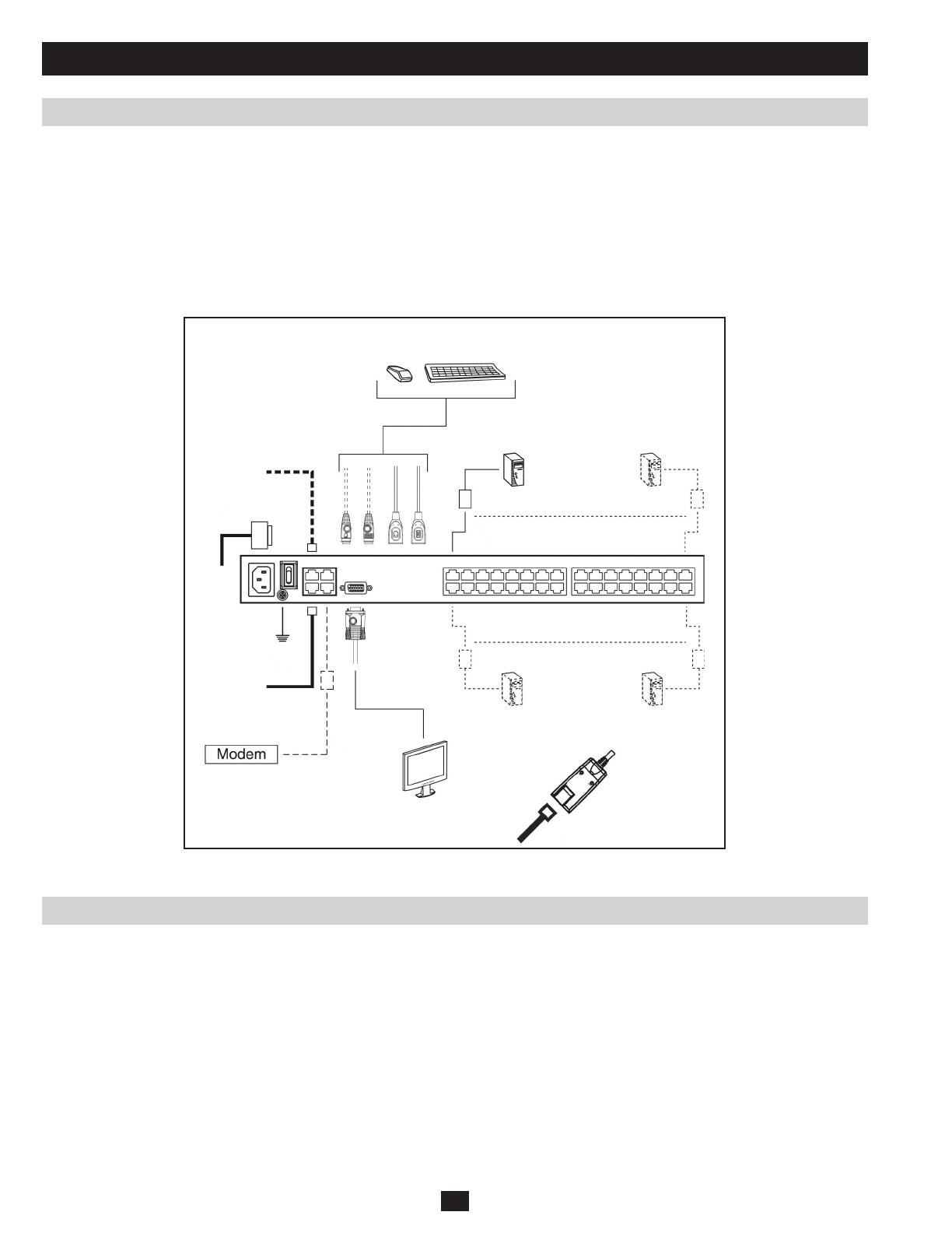
In a Single Stage installation, there are no additional KVM switches cascaded and/or daisy-chained from the B064-Series KVM. To set up a
single stage installation, refer to the following instructions and the corresponding installation diagrams starting on page 10.
1. Make sure that power to all the devices you will be connecting, including all pre-existing devices on the installation, have been turned off.
2. Optional: Plug your Local Console’s keyboard, monitor, and mouse into the KVM’s Local Console Ports. You will need to connect the
included USB – PS/2 Console Cable Kit to the console port on the back of the unit.
Note: You can use any combination of keyboard and mouse connections. For example, you can use a PS/2 keyboard with a USB mouse. USB
keyboards and mice can plug into the USB ports on the front panel, as well as the ports on the USB – PS/2 Console Cable Kit. The B064-Series
KVM Switch does not support distances above 65 ft between the KVM and the local monitor.
3. Use Cat5e cable to connect any available KVM port to a B054-001-PS2 (for PS/2 Servers) or B054-001-USB (for USB Servers) Server
Interface Unit.
Note: The distance between the B064-Series KVM and the Server Interface Unit must not exceed 130 ft.
4. Connect the Server Interface Unit to the computer/server.
5. Connect a Cat5e cable from the network into the KVM switch’s primary network port (LAN 1).
Stacking
Rack Mounting
Single Station Installation
2
4
6
9
8
5
7
2
3
3
10
6. Optional: Connect a second Cat5e cable from the network into the KVM switch’s backup (secondary) network port (LAN 2).
7. Optional Dial-In Modem Connection: Use Cat5e cable to connect the KVM switch’s Modem port to the included RJ45 to DB9 Adapter, and
connect the adapter’s DB9 connector to the modem’s DB9 port.
8. Use the included grounding wire to ground the unit. Connect one end of the wire to the grounding terminal, and the other end of the wire to a
suitable grounded object.
9. Plug the included power cord into the KVM switch’s Power Socket, and then into a Tripp Lite Surge Suppressor, Uninterruptible Power Supply
(UPS) or PDU.
10. Turn on the power to the KVM switch. Once it is powered up, turn on the power to the connected computers.
Single Station Installation (continued)
Two Stage Installations
Hardware Setup
Up to 32 additional KVM switches can be cascaded from the KVM ports of the B064- Series KVM Switch in order to expand the number of
connected computers/servers. In a cascaded installation, the top B064-Series KVM Switch is considered the First Stage unit, the cascaded
switches are considered Second Stage units.
To set up a two stage installation, refer to the instructions below:
1. Make sure that power to all the devices you will be connecting, including all pre-existing devices on the installation, have been turned off.
2. Use Cat5e patch cable to connect any available KVM Port on the First Stage unit (the B064-Series KVM Switch) to a B054-001-PS2 PS2
Server Interface Unit.
3. Plug the B054-001-PS2s KVM connectors to the Keyboard, Video, and Mouse Console ports of the Second Stage unit.
Note: The distance between the Second Stage unit and the First Stage Unit must not exceed 130 ft.
4. Use the appropriate KVM Cable Kits (See the Second Stage KVMs owner’s manual), to connect any available KVM port on the Second Stage
unit to the Keyboard, Video and Mouse ports of the computer/server you are installing.

11
TheB064-SeriesKVMSwitchessupporthotplugging;componentscanberemovedandaddedbackintotheinstallationbyunpluggingandre-
plugging their cables from the ports without the need to shut the unit down. However, if you change computer positions, in order for the OSD
menus to correspond to the KVM port changes, you must manually re-edit the Port Names to reflect the new port information.
Note: If the computer’s Operating System does not support hot plugging, this function may not work properly.
If it becomes necessary to power off the B064-Series KVM Switch, or the switch loses power and needs to be restarted, wait 10 seconds before
powering it back on. The computers should not be affected by this, but if any of them should fail, simply restart them.
Each computer on the installation is assigned a unique Port ID. The Port ID is a one or two segment number that is determined by the Stage Level
and KVM port number of the KVM switch that the computer/server is connected to.
Single Stage Installations
Single stage installations will have a one segment Port ID consisting of two digits.
(For example, a computer/server connected to port 19 of a B064-032-04-IP will have a Port ID of 19. A computer/server connected to port 9 of a
B064-032-04-IP will have a Port ID of 09)
Two Stage Installations
Two stage installations will have a two segment Port ID consisting of 4 digits. (2 digits per segment)
• TherstsegmentofthePortIDrepresentstheportnumberoftheFirstStageKVMswitchthatthecascadedunitisconnectedto.
• ThesecondsegmentofthePortIDrepresentstheportnumberoftheSecondStageKVMswitchthatthecomputer/serverisconnectedto.
(For example, a computer attached to port 3 of a second stage KVM switch that is connected to port 15 of the first stage KVM switch will have a
Port ID of 03-15)
Two Stage Installations (continued)
Hot Plugging
Powering Off and Restarting
Port ID Numbering
Hardware Setup
5. Plug the power cord that came with the cascaded KVM switch into its Power Socket, and then into a Tripp Lite Surge Suppressor,
Uninterruptible Power Supply (UPS) or PDU.
6. Repeat these steps for any other Second Stage units you wish to connect.
7. First power on the B064-Series KVM Switch and then power on all second-stage KVM switches.
8. Turn on the power to all of the connected computers/servers.
Note: The Power On sequence requires that the B064-Series KVM Switch be powered on first. After the B064-Series KVM Switch has been
powered on, all second-stage units must be powered on. After the second-stage units have been powered on, the connected computers/servers
can be powered on.
12
The B064-Series KVM Switches supports three types of users, as shown in the table below:
User Type Description
Super Administrator
Super Administrators have full access to all Ports and Devices in the KVM installation. They can manage all aspects of the
installation.
Administrator
Administrators have access to Ports and Devices that are authorized by the Super Administrator. They can manage Users
and Groups and configure their personal working environment.
User
Users can access Ports and Devices authorized by Super Administrators or Administrators and they can configure their
personal working environment.
First Time Setup
Network Setup - IP Address Determination
Super Administrator Setup
Once the B064-Series KVM Switch has been installed, the Super Administrator needs to set the unit up for user operation. This involves setting
the network parameters and adding users.
If you are an administrator logging in for the first time, you need to
access the B064-Series KVM Switch in order to give it an IP address
thatuserscanconnectto.Therearefourmethodstochoosefrom;
Local Console, IP Installer, AP Windows Client and Browser.
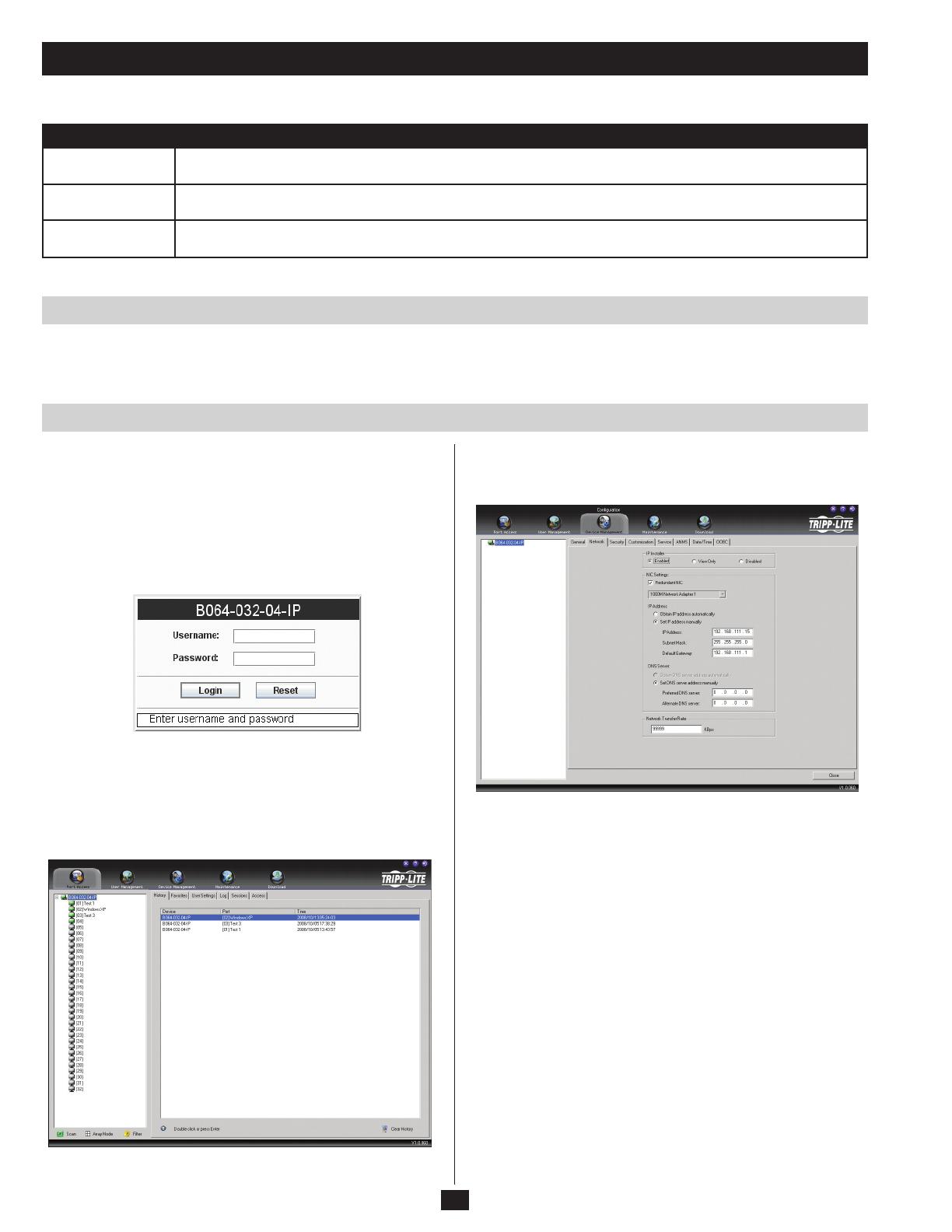
Local Console
After the local console has been connected and the B064-Series KVM
Switch is turned on, a login prompt appears on the console monitor:
Log in using the default Username: administrator and Password:
password. For security purposes, it is strongly recommended that you
change these to a unique Username and Password. (See Changing the
Super Administrator Login, page 14 for details.)
After you successfully log in, the Local Console Main Screen
appears:
1. Click the Device Management icon at the top of the screen.
2. On the notebook screen that appears on the right-hand side of the
page select the Network tab.
Super Administrator Setup
NIC Settings
13
The B064-Series KVM Switch is designed with two network
interfaces. The NIC Setting section of the Network tab allows you
to assign a single IP Address and DNS Server for both network
interfaces, or to assign a separate address for each.
Redundant NIC
If Redundant NIC is enabled (the default), both interfaces use the IP
address assigned to Network Adapter 1. Under this configuration, the
B064-Series KVM Switch will switch to the second network interface
in the event there is a crash on the first network interface.
• IfyouselectRedundantNIC,theNetwork Interface drop-down
menu will be frozen to Network Adapter 1, and you will only have
to enter IP Address and DNS Server settings once.
• IfyoudonotselectRedundantNIC,youwillhavetoenterIP
Address and DNS Server settings for both Network Adapter 1 and
Network Adapter 2. User the Network Interface drop-down menu to
select the Network Adapter you want to configure.
IP Address
The B064-Series KVM Switch can either have its IP address assigned
dynamically (DHCP), or it can be given a fixed IP address.
• FordynamicIPaddressassignment,selecttheObtain IP address
automatically option
• ToassignanIPaddressyourself,selecttheSet IP address manually
option and fill in an IP Address, Subnet Mask and Default Gateway
appropriate for you network
DNS Server
As with the IP Address, you have the option of having the DNS Server
set automatically or setting it yourself.
• ForautomaticDNSServeraddressassignment,selecttheObtain
DNS Server address automatically option
• TospecifytheDNSServeraddressmanually,selecttheSet
DNS server address manually option, and enter in Preferred and
Alternate DNS servers that are appropriate for your network
Note: If you choose to enter the DNS Server manually, it is required
that you specify the preferred DNS Server address. The alternate
DNS Server address is optional.
See pages 41-42 for more information on the settings in the Network
tab of the Device Management section.
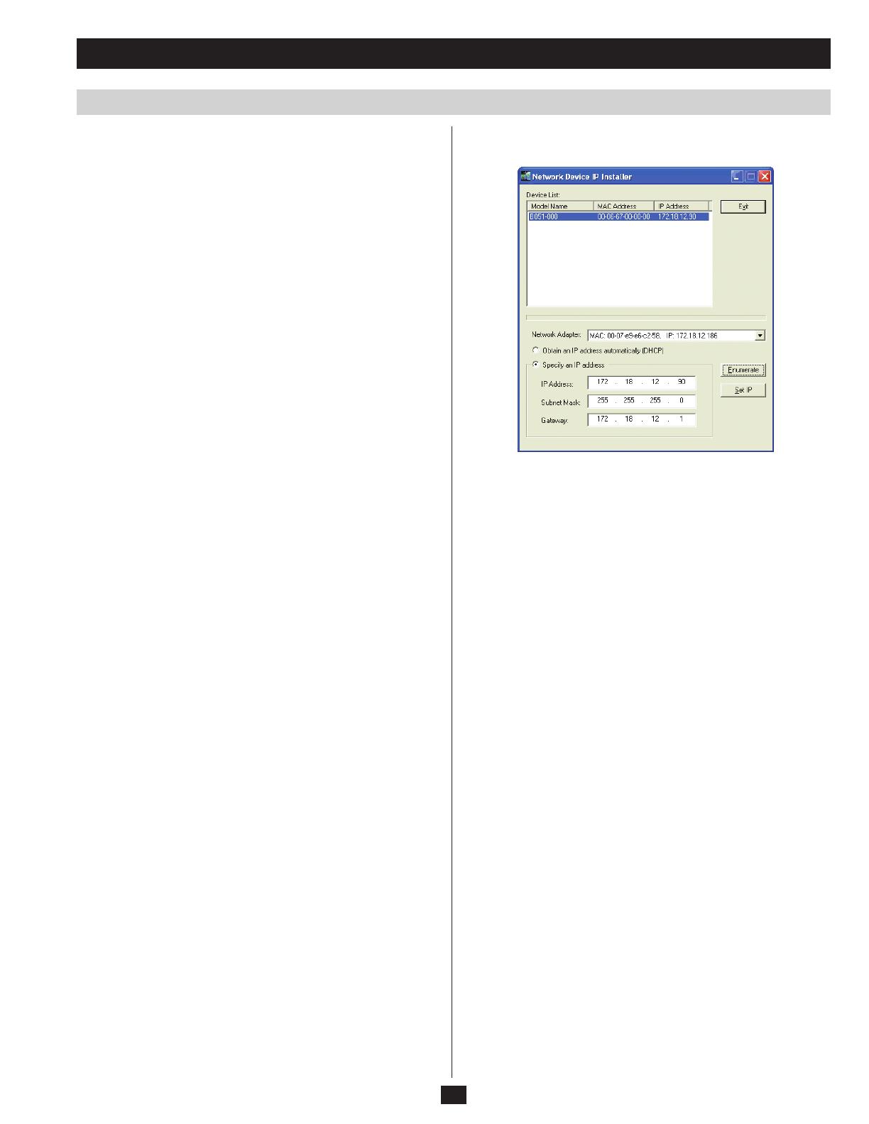
IP Installer
For computers running Windows, an IP address can be assigned with
the IP Installer utility:
1. Obtain the IP Installer file from the CD that came with the B064-
Series KVM Switch and save it to a desired location on a computer
that is on the same network as your B064-Series KVM Switch.
2. Go to the IP Installer file that you just saved and run the IPInstaller.
exe file. A dialog box similar to the one below appears:
3. Select the B064-Series KVM Switch in the Device List.
Note: If the list is empty, or your device doesn’t appear, click
Enumerate to refresh the Device List. If there is more than one device
in the list, use the MAC address to pick the one you want. The B064-
Series KVM Switches MAC address is located on its bottom panel.
4. From here you can choose to Obtain an IP address automatically
(DHCP), or Specify an IP address. If you choose to assign your
own address, fill in the IP Address, Subnet Mask, and Gateway
fields with information appropriate to your network.
5. Click Set IP.
6. After the IP address shows up in the Device List, click Exit.
Browser
1. On a computer/server that is on the same network as your B064-
Series KVM Switch, set the computer/server’s IP address to
192.168.0.XXX, where XXX represents any number or numbers
except 60. (192.168.0.60 is the default address of the B064-Series
KVM Switch.)
2. Access the B064-Series KVM switch using the URL 192.168.0.60
3. Assign a fixed IP address for the B064-Series KVM Switch using
the same instructions as described in the Local Console section of
this chapter.
4. After you log out, reset your computer’s IP address to its original
value.

14
Super Administrator Setup
NIC Settings
Changing the Super Administrator Login
Moving On
AP Windows Client
For computers running Windows, the B064-Series KVM Switch’s IP
address can be determined using the AP Windows Client that comes
on the B064-Series KVM Switch CD. When you run the program it
searches the network segment for B064-Series KVM Switch devices,
and displays the results in a dialog box similar to the one below:
You can use the network address found here to access the B064-Series
KVM Switch. Once you login to the KVM switch, you can change
the IP Address using the instructions in the Local Server and Browser
sections of this chapter.
To change the default Super Administrator Username and Password,
do the following:
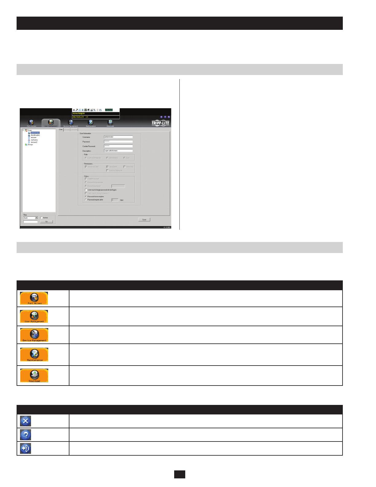
1. At the top of the Web page, click User Management.
The User Management page has a list of Users and Groups in the left
hand panel, and a more detailed list of users in a large central panel.
Since this is the first time the page is being accessed, only the Super
Administrator appears:
2.ClickAdministratorintheleftpanel;or,selectAdministratorinthe
central panel and click the Modify button at the bottom of the page.
The User Information page appears:
3. Change the Username and Password to something unique.
4. Re-enter the password to confirm it is correct.
5. Click Save.
6. When the dialog box informing you that the change completed
successfully appears, click OK.
7. Click on an item in the left-hand panel to close the User Information
page.
After setting up the network and changing the default Super Administrator username and password, you can proceed to other administration
activities. These include User Management, Device Management, and Firmware Upgrade Maintenance.
15
Accessing the B064-Series KVM Switch
Local Console Login
Browser Login
The B064-Series KVM Switches can be accessed in the following ways: via local console, an internet browser, the AP Windows Client and/or
the AP Java Client. Operating the KVM switch and configuring its settings is done the same regardless of how you connect to the B064-Series
KVMSwitch;theonlydifferenceisthewayinwhichyouestablishtheconnection.Thischapterdescribestheloginproceduresforeachofthese
methods.
As described at the beginning of Chapter 3, Super Administrator Setup, the local console login dialog box is displayed once the installation is
complete. When the local console is attached, and there is no user logged in, the login screen will appear on the display. Simply key in your
Username and Password and click Login to bring up the OSD Main Page.
Note: If you supply an invalid login, the authentication routine will return an Invalid Username or Password message. If you see this message,
log in again being careful to enter the correct Username and Password.
The B064-Series KVM Switches can be accessed via Internet browser
from any platform that has the Java Runtime Environment 6, Update
3, or higher installed. If you don’t already have the required JRE
installed, it is available for free download from the Java web site:
www.java.com
To access the switch via browser, do the following:
1. Open the browser and specify the IP address of the B064-Series
KVM Switch you want to access, as given to you by your system
administrator.
Note: For security purposes, a login string may have been set by the
administrator. If so, you must include a forward slash and the login
string along with the IP address when you log in. (For example, a
computer with a login string of B064-032-04-IP would have a URL
such as 192.168.0.100/B064-032-04-IP)
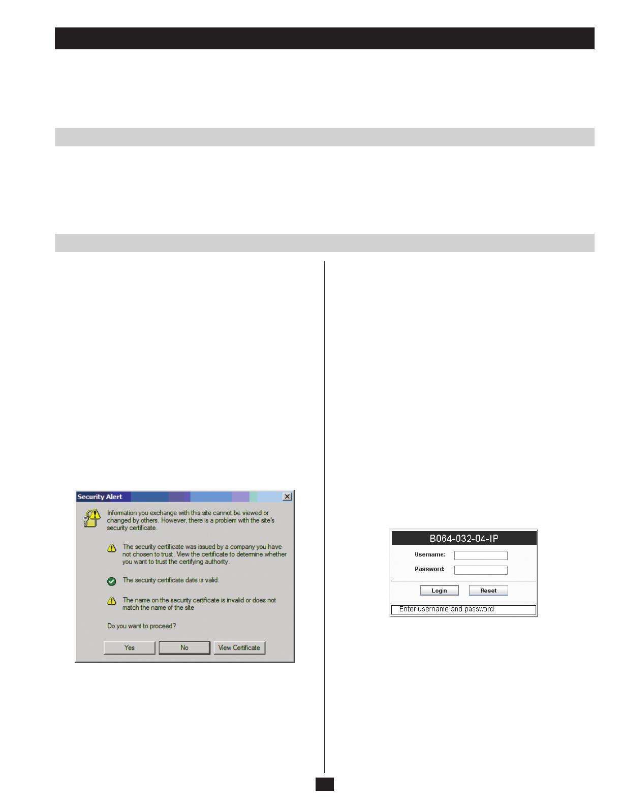
2. When you try to log into the device from your browser, a Security
Alert message appears to inform you that the device’s certificate is
not trusted, and asks if you want to proceed. The certificate can be
trusted, but the alert is triggered because the certificate’s name is
not found on Microsoft’s list of Trusted Authorities.
You have two options:
• Ifyouareworkingonacomputerotherthanyourown,acceptthe
certificate for just this session by clicking Yes.
• Ifyouareworkingatyourowncomputer,installthecerticate.
After the certificate is installed, it will be recognized as trusted. To
install the certificate, do the following:
a) In the Security Alert dialog box, click View Certificate. The
Certificate Information dialog box appears.
Note: There is a red and white X over the certificate to indicate
that it is not trusted.
b) Click Install Certificate.
c) Follow the Installation Wizard to complete the installation.
Unless you have a specific reason to choose otherwise, accept the
default options.
d) When the Wizard presents a caution screen, click Yes.
e) Click Finish to complete the installation and click OK to close
the dialog box. The certificate is now trusted.
Upon installing the certificate or accepting the unrecognized
certificate for the current session, the browser login dialog box
appears.
3. Provide a valid Username and Password (set by the KVM switch’s
administrator), and click Login to bring up the OSD Main Page.
Note: If you supply an invalid login, the authentication routine will
return an Invalid Username or Password message. If you see this
message, log in again being careful to enter the correct Username
and Password.

16
Accessing the B064-Series KVM Switch
AP Windows Client Login
The Connection Screen
The File Menu
In some cases, the Administrator may not want the B064-Series KVM
Switches to be available via browser. The Windows AP Client allows
Windows systems users access to the KVM switch without having to
go through a browser.
The AP Windows Client can be found in the Download Section of the
OSD or on the CD that came with your B064-Series KVM Switch.
If you do not have access to the CD, and browser access to the KVM
switch has already been disabled, you will need to obtain the file from
your system administrator. Once you have saved the AP Windows
Client, go to its location and double-click the WinClient.exe icon to
bring up the Windows Client Connection Screen:
A description of the contents of the Connection Screen is given in the following table:
Item Description
Menu Bar The Menu Bar contains three menus; File, Tools and Help
• The File Menu allows the operator to Create, Save, and Open Work les.
• The Tools Menu contains one entry; Hotkey Setup. (See Hotkey Setup, page 19)
Server List
Each time the WinClient.exe file is run, it searches the User’s LAN segment for B064-Series KVM Switches, and lists the
ones it finds in this box. Double-click on any of the units in this list to connect to it.
Server This area is used when you want to connect to a B064-Series KVM Switch at a remote location.
• Click on the IP drop-down and select an address from the list. If the address you want is not listed, key in the target IP
address in the IP field, and its port number in the Port field.
• When the IP address and port number have been specied, click Connect to bring up a login dialog box. Provide a
Username and Password as provided by your system administrator and click OK to establish a connection with the B064-
Series KVM Switch.
• When you have nished with your session, click Disconnect to end the connection.
Message List Lists status messages regarding the connection to the B064-Series KVM Switch.
Switch to Remote
View
Once a remote connection with a B064-Series KVM Switch has been established, this button becomes active. Click it to
switch to the KVM Switch’s Main OSD Page.
The File Menu allows the operator to Create, Save, and Open Work files. A Work File consists of all the information specified in a Client session.
This includes the items in the Server List and Server IP list, as well as the Hotkey settings.
Whenever a user runs the Client program, it opens with the values contained in the current work file. The current work file consists of the values
that were in effect the last time the program was closed.
The File menu consists of three items:
Item Description
New Allows the user to create a named work file so that its values will not be lost and will be available for future use
Open Allows the user to open a previously saved work file and use the values contained in it
Save Allows the user to save the values presently in effect as the current work file
17
Accessing the B064-Series KVM Switch
The Tools Menu
AP Java Client Login
Tools Menu operations are performed after you connect to the B064-Series KVM Switch, but before you switch to remote view. There is only one
optionintheToolsMenu;HotkeySetup.(Seepage19fordetails)
In those cases in which the Administrator does not want the B064-
Series KVM Switch to be available via browser and the remote user is
not running Windows, the AP Java Client provides access to the KVM
switch.
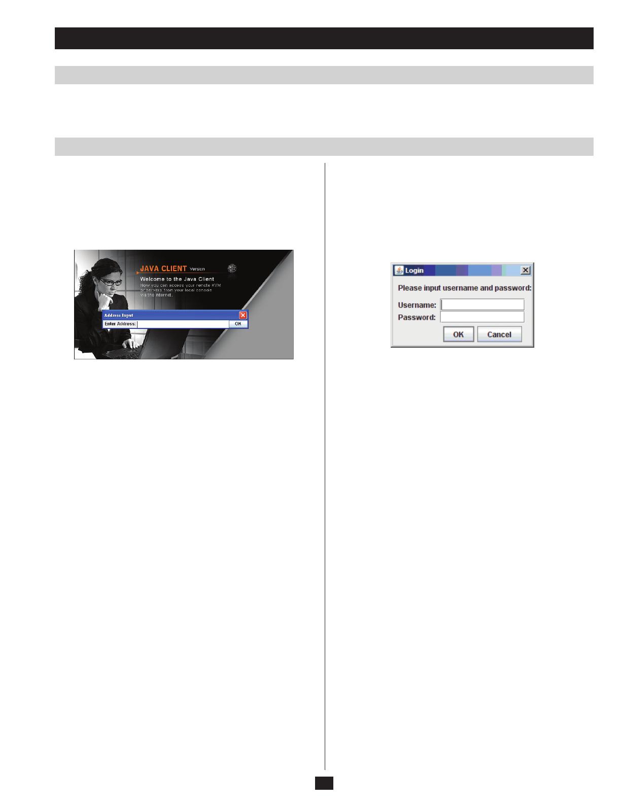
After downloading the AP Java Client, go to the location on your
hard disk where you downloaded the program and double-click the
JavaClient.jar icon to bring up the Address Input dialog box:
1. Key in the IP address for the unit you want to connect to, as given
to you by your system administrator. For security purposes, a login
string may have been set up by the administrator. If a login string
has been set up, a forward slash followed by the login string must
be specified as part of the IP address. (For example, a computer
with a login string of B064-032-04-IP would have a URL such as
192.168.0.100/B064-032-04-IP)
2. Click OK. A Login dialog box appears:
3. Provide a valid Username and Password, as given to you by your
system administrator, and click OK to switch to the OSD Main
Page.
18
The OSD Main Page
The OSD Main Page
OSD Icon Bar
When the OSD Main Page appears, the Port Access page is displayed.
There is an icon bar across the top of the page, as well as a hidden
Control Panel at the upper or lower center of the screen that becomes
visible when you mouse over it:
After you have successfully logged into the B064-Series KVM Switch, the OSD Main Page appears. This chapter describes the functionality of
the OSD Main Page.
Note: The screen shown depicts a Super Administrator’s page.
Depending on your user type and permissions, some of these elements
will not appear on your OSD Main Page. Also, the Control Panel
will not be accessible when accessing the KVM switch via the local
console.
The number and type of icons that appear on the icon bar at the top of the page are determined by user type (Super Administrator, Administrator
or User) and the permissions assigned when the account was created. The functions associated with each of the icons are explained in the table
below:
Icon Description
Port Access: This page is used to access and control the devices on the KVM switch installation. This page is available to
all users.
User Management: This page is used to create and manage Users and Groups, and to assign devices to them. This page
is available to Super Administrator and Administrators, ordinary users will not have access to it.
Device Management: This page is used by the Super Administrator to configure and control the overall operation of the
KVM switch. This page is available to Super Administrators or Administrators/Users who have been given access.
Maintenance: This page is used to install new versions of the B064-Series KVM Switch firmware. This page is available
to Super Administrators or Administrators/Users who have been given access. Note: The Maintenance icon is not available
via the local console.
Download: Users with appropriate permission can click this icon to download the AP Windows Client, the AP Java Client
and the Log Server. This page is available to all users, although what downloads a User can access is determined by the
Super Administrator or Administrator. Note: The Download icon is not available via the local console.
There are three small icons in the upper right-hand corner of the page. Their functions are described in the table below:
Icon Description
Click this icon to close the OSD page and return to the display of the last selected port.
Click this icon to display the firmware version of the B064-Series KVM Switch.
Click this icon to log out and end your B064-Series KVM Switch session.

19
The OSD Main Page
The Control Panel
The Control Panel consists of three rows: a row of icons at the top,
with two text rows below. The Control Panel is only available when
accessing the KVM switch remotely, and will not be accessible via the
local console.
Ordinarily, the text bars display the video resolution and IP address of the device at the remote location. As the mouse pointer moves over the
icons in the icon bar, the information in the text bar changes to describe the icon’s function. To move the Control Panel to a different location on
the screen, place the mouse pointer over the text bar area, and click and drag it to the desired location.
Icon Description
Click this button to keep the Control Panel displayed all the time, or to have it hide itself automatically when not in use.
Click to bring up the Hotkey Setup dialog box. Note: The Hotkey Setup icon is only accessible when accessing the B064-
Series KVM Switch using the AP Windows Client
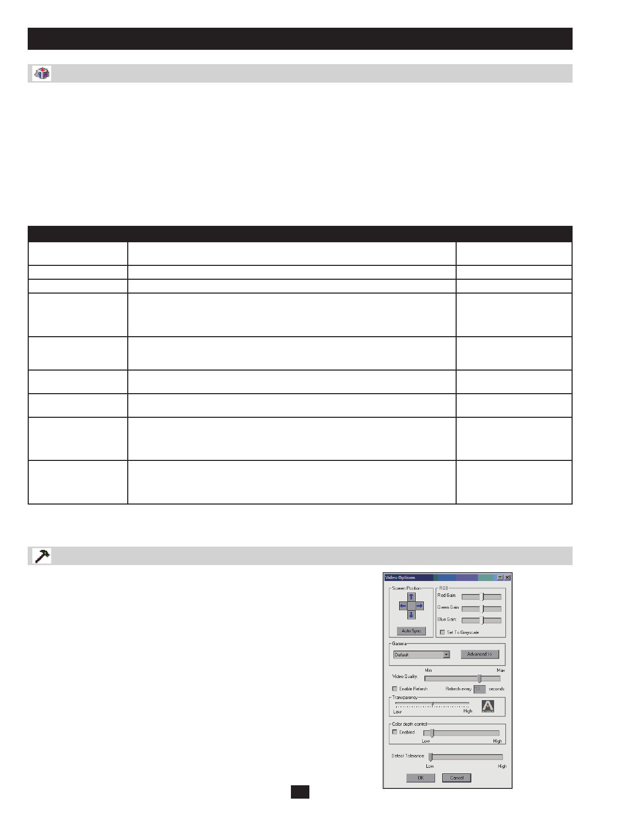
Click to bring up the Video Options dialog box. Right-click to perform a quick Auto Sync. (See Video Settings on pages 20-
21 for details)
Left click to toggle Full Screen Mode on and off. Right click to toggle Keep Screen Size on and off.
Click to bring up the Message Board. (See The Message Board on page 22 for details)
Click to send the Ctrl+Alt+Del command to the remote system.
Click to toggle the remote display between color and gray scale.
Click to bring up the on-screen keyboard. (See the On-Screen Keyboard on page 23 for details)
Click to toggle Automatic or Manual mouse sync on/off. (See Mouse Sync Mode on page 23 for details)
• When the selection is Automatic, a green 4 appears on the icon.
• When the selection is Manual, a red X appears on the icon.
Note: The Automatic feature only supports USB mice on Windows and Mac (G4 or higher) systems. This icon only
becomes active when you are connected to a port that has an online computer matching those requirements – in other
cases, the icon is inactive and only the manual method is available.
Click this icon to end the remote session and log out. This will log you out of the KVM switch, requiring you to enter your
username and password to regain access. If you want to go back to the OSD menu, use the hotkey command to bring up
the remote toolbar, and click on the icon to bring up the OSD Toolbar. (See page 59 for details)
These LEDs show the Num Lock, Caps Lock, and Scroll Lock status of the remote computer. Click on the icon to toggle the
status on/off. Note: When you first connect, the LED display may not be accurate. To be sure, click on the LEDs to set them.
Hotkey Setup
Note: Hotkey functionality is only accessible when accessing the
B064-Series KVM Switch via the AP Windows Client. You will not be
able to access this feature via web browser.
Various actions related to manipulating the remote server can be
accomplished with hotkeys. The Hotkey Setup utility lets you
configure which hotkeys perform these actions. The Action panel on
the left lists the different actions you can perform via hotkey. The
Hotkeys panel on the right displays the hotkey commands that invoke
these actions.
20
The OSD Main Page
Hotkey Setup (continued)
Video Options
The following steps will enable you to reconfigure the default Hotkey combinations:
1. Highlight the Action you wish to change and click Start.
2. Key in the Function keys (one at a time). The key names appear in the key field as you press them.
3. When you have finished keying in your sequence, click Stop.
4. Click Set.
5. Click Close.
Note: You can use the same function keys for more than one action, as long as the first key is not the same. For example, you can use F1 F2 F3
for one action; F2 F1 F3 for another; F3 F2 F1 for a third, etc.
An explanation of the Hotkey actions is given in the table below:
Action Description Default Hotkey Command
Exit Remote Location Breaks the connection to the B064-Series KVM switch and returns you to local
computer operation.
F2, F3, F4
Adjust Video Brings up the video adjustment utility. F5, F6, F7
Toggle OSD Toggles the OSD display Off and On. F3, F4, F5
Toggle mouse display Use this hotkey command to turn the local mouse pointer into a barely-noticeable tiny
circle. This allows the user to concentrate more on the remote mouse pointer. Since
this is a toggle, use the hotkeys again to bring the mouse display back to its original
configuration.
F7, F8, F9
Adjust mouse This hotkey command synchronizes the local and remote mouse pointers following a
video resolution change. After invoking this utility, click the local mouse pointer on top of
the remote mouse pointer to enact the sync.
F8, F7, F6
Video Auto-sync This hotkey command performs an auto-sync operation. It is the same as clicking the
Auto-sync button in the Video Options dialog box.
F6, F7, F8
Show/Hide Local
Cursor
Toggles the local mouse pointer off and on. As opposed to the Adjust mouse command,
this command will hide the local mouse pointer altogether.
F4, F5
Substitute Alt key Although all other keyboard inputs are captured and sent to the remote computer, [Alt
+ Tab] and [Ctrl + Alt + Del] are sent to your local computer. In order to use them on a
remote system, another key may be substituted for the Alt key. If you substitute the F11
key, for example, you would use [F11 + Tab] and [Ctrl + F11 + Del].
F11
Substitute Ctrl key If your local computer captures Ctrl key combinations, preventing them from being
sent to the remote system, you can implement their effects on the remote system by
specifying a function key to substitute for the Ctrl key. If you substitute the F12 key, for
example, pressing [F11 + 5] would appear to the remote system as [Ctrl + 5].
F12
Note: To invoke an action, you must press and release the keys one key at a time. The command will not take effect if you press all keys at the
same time.
Clicking the Hammer icon on the Control Panel brings up the Video
Settings dialog box. The dialog box allows you to adjust the placement
and picture quality of the remote screen on your monitor:
/