Electrolux EIED200QSW00 Installation guide
- Category
- Tumble dryers
- Type
- Installation guide
This manual is also suitable for

Electrolux
o_o oe ooeses®s®so oo ®oese ® • s ® • • • • • • s • • s • • s • • • •
EN FRONT LOAD DRYER INSTALLATION INSTRUCTIONS
FR SECHEUSEA CHARGEMENT FRONTAL INSTRUCTIONS D'INSTALLATION
ES SECADORA DE CARGA FRONTAL INSTRUCCIONES DE INSTALACION

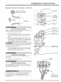
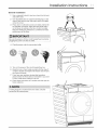
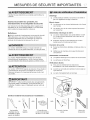
IMPORTANT SAFETY INSTRUCTIONS
For your safety the information in this manual must be followed to minimize the risk of fire or explosion or to prevent property
damage, personal injury or loss of life. Do not store or use gasoline or other flammable vapors and liquids in the vicinity of
this or any other appliance.
I G- O FI E
Read all of the following instructions before installing and using this appliance:
* Destroy the carton and plastic bags after the dryer is unpacked. Children might use them for play. Cartons covered with
rugs, bedspreads, or plastic sheets can become airtight chambers causing suffocation. Place all materials in a garbage
container or make materials inaccessible to children.
* Clothes dryer installation and service must be performed by a qualified installer or service agency.
* Install the clothes dryer according to the manufacturer's instructions and local codes.
* The electrical service to the dryer must conform with local codes and ordinances and the latest edition of the National
Electrical Code, ANSI/NFPA 70, or in Canada, the Canadian electrical code C22.1 part 1.
* The dryer is designed under ANSI Z 21.5.1 or ANSl/UL 2158 - CAN/CSA C22.2 No. 112 (latest editions) for HOME USE
only. This dryer is not recommended for commercial applications such as restaurants, beauty salons, etc.
* Do not stack a dryer on top of washer already installed on pedestal. Do not stack dryer on top of another dryer. Do not stack
washer on top of dryer. Do not stack washer on top of another washer. Do not stack dryer on top of washer without use of
manufacturer approved and correctly installed stacking kit appropriate for your model.
* The instructions in this manual and all other literature included with this dryer are not meant to cover every possible condi-
tion and situation that may occur. Good safe practice and caution MUST be applied when installing, operating and maintain-
ing any appliance.
To avoid back or other injury, have more than one person
movt !he ...............................................................................................................................................................
EXPLOSION HAZARD
Do not install the dryer where gasoline or other flammables
are kept or stored. If the dryer is installed in a garage, it
must be a minimum of 18 inches (45.7 cm) above the floor.
Failure to do so can result in death, explosion, fire or burns.
SAVE THESE INSTRUCTIONS
FOR FUTURE REFERENCE.
TABLE OF CONTENTS
Important Safety Instructions .............................................. 2-3
Installation Requirements ................................................... 4-8
Installation Instructions ..................................................... 6-11
Reversing Door ............................................................... 12 -13
Accessories ......................................................................... 14
Notes ................................................................................... 18
Fran£ais ............................................................................... 16
Espafiol ................................................................................ 30

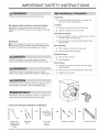
IMPORTANT SAFETY INSTRUCTIONS
Recognize safety symbols, words and labels
Safety items throughout this manual are labeled with a
WARNING or CAUTION based on the risk type as described
below:
Definitions
d_,This is the safety alert symbol. It is used to alert you to
potential personal injury hazards. Obey all safety messages
that follow this symbol to avoid possible injury or death.
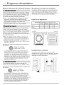
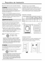
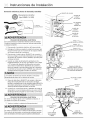
Unpacking
[3 Plastic film (lining drum interior) is removed and
discarded. See also image below.
Leveling
[3 Dryer is level, side-to-side and front-to-back
[3 Cabinet is setting solid on all corners
240v Electric Supply
[3 Approved NEMA 10-30R or 14-30R service cord with
all screws tight on terminal block
[3 Terminal access cover/strain relief installed before
initial operation
Door Reversam
[3 Follow detailed instructions in this guide
[3 Test hinge and latch for function
EmectricaN Power
[3 House power turned on
DANGER indicates an imminently hazardous situation [3 Dryer plugged in
which if not avoided, will result in death or serious injury.
Final Checks
[3 Installation Instructions and Use and Care Guide
read thoroughly
[3 Door latches and drum tumbles when cycle starts
WARNING indicates a potentially hazardous situation
which_ !! n0t avo!ded, cou!d !esu!t in death seEi0us !nju!y:............. [3 Registration card sent in
information which is important but not hazard-related.
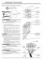
Tools and materials needed for installation:
OR AND AND AND
Optional uni- Adjustable 3 or 4-wire
versal wrench pliers 240 volt
available from cord kit
dealer
Phillips screwdriver Carpenter's level

.........Installation Requirements
Electrical requirements for electric dryer
Because of potentially inconsistent voltage capabilities,
the use of this dryer with power created by gas powered
generators, solar powered generators, wind powered
generators or any other generator other than the local utility
company is not recommended. ................
CIRCUIT - Individual 30 amp. branch circuit fused with 30
amp. time delay fuses or circuit breakers. Use separately
fused circuits for washer and dryer. DO NOT operate a
washer and a dryer on the same circuit.
POWER SUPPLY -3-wire or 4-wire, 208-240 volt, single
phase, 60 Hz, Alternating Current.
Manufactured or mobile home installation
Installation MUST conform to current Manufactured Home
Construction & Safety Standard, Title 24 CFR, Part 32-80
(formerly the Federal Standard for Mobile Home Construction
and Safety, Title 24, HUD Part 280) or Standard CAN/
CSAZ240 MH.
Clearance requirements
MINIMUM INSTALLATION CLEARANCES - inches (cm)
SIDES REAR TOP FRONT
Alcove 0" (0 crn) 0" (0 cm)* 0" (0 crn) n/a
Under Counter 0" (0 crn) 0" (0 cm)* 0" (0 crn) n/a
This dryer is internally grounded to neutral unless itwas
manufactured for sale in Canada.
Only a 4-conductor cord shall be used when the appliance
is installed in a location where grounding through the
neutral conductor is prohibited. Grounding through
the neutral link is prohibited for: (1) new branch circuit
installations, (2) mobile homes, (3) recreational vehicles,
and (4) areas where local codes do not permit grounding
through the neutral. .............
OUTLET RECEPTACLE - NEMA 10-30R or NEMA 14-30R
receptacle to be located so the power supply cord is
accessible when the dryer is in the installed position.
GROUNDING CONNECTION - See 'Grounding requirements"
in Electrical Installation section.
(ecru} " (ocm}
4-WIREPOWERSUPPLYCORDKIT(notsupplied)
4-wire receptacle
(NEMA type 14-30R)
The dryer MUST employ a 4-conductor power supply
cord NEMA 14-30 type SRDT or ST (as required) rated
at 240 volt AC minimum, 30 amp, with 4 open end
spade lug connectors with upturned ends or closed loop
connectors and marked for use with clothes dryers. For
4-wire cord connection instructions see ELECTRICAL
CONNECTIONS FOR A 4-WIRE SYSTEM.
Dryers manufactured for sale in Canada have factory-
installed, 4-wire power supply cord (NEMA 14-30R).
3-WIRE POWER SUPPLY CORD KIT (not supplied)
3-wire receptacle
(NEMA type 10-30R)
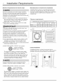
Closet installation
If installing the dryer in a closet, the unit must only be
operated with the door in the open position to allow correct air
circulation. See Use and Care Guide for more information.
ZZ3_
-- TZ2:Z2_
The dryer MUST employ a 3-conductor power supply cord
NEMA 10-30 type SRDT rated at 240 volt AC minimum, 30
amp, with 3 open end spade lug connectors with upturned
ends or closed loop connectors and marked for use with
clothes dryers. For 3-wire cord connection instructions see
ELECTRICAL CONNECTIONS FOR A 3-WIRE SYSTEM.

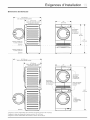
Installation Requirements
Dryer Dimensions
_t, 43" (109 cm) d°°_
to clear open door
24" (61 cm)
to front of closed
.,.1
freestand dryer
on floor
floor line
2_
2_
dryer mounted on
optional pedestal
floor line
•_ 24" I_
(60,5 cm)
0"
, = ,
...........r _
electrical
supply on
rear of unit I
33,5"
(85 cm)
46"
(116,5 cm)
43" (109 cm)
to clear open door
26'* (66 cm)
to front of closed door
floor line
I i
I !
! f
water supply
connection on
rear of unit
\
\
\
\
_1_ 24" I_ I
(60,5 cm)
electrical
supply on
rear of unit I
drain hose on
rear of unit 2
68,5"
(174 cm)
power cord on
rear of uniP
_Power supply cord length on Canadian dryer approximataly 59 inches (150 cm).
2Drain hose length on washer approximately 55 inches (140 cm),
_Power supply cord length on washer approximataly 59 inches (150 cm).

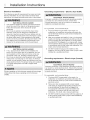
..........Installation Instructions
Electrical installation
Grounding requirements - Electric dryer (USA)
The following are specific requirements for proper and safe
electrical installation of your dryer. Failure to follow these
instructions can create electrical shock and/or a fire hazard.
Improper connection of the equipment grounding conductor
........................................................ can result in a risk of electrical shock. Check with a
ELEcTRiCAL SHOCK HAZARD licensed electrician if you are in doubt as to whether the
appliance is properly grounded.
• This appliance MUST be properly grounded. Electrical
shock can result ifthe dryer is not properly grounded.
Follow the instructions in this manual for proper
grounding.
• Do not use an extension cord with this dryer. Some
extension cords are not designed to withstand the
amounts of electrical current this dryer utilizes and can
melt, creating electrical shock and/or fire hazard. Locate
the dryer within reach of the receptacle for the length
power cord to be purchased, allowing some slack in the
cord. Refer to the pre-installation requirements in this
..................manua !o!h p!op_ powe co b pu!chased.............................
ELECTRICAL SHOCK HAZARD
• A U.h-approved strain relief must be installed onto
power cord. If the strain relief is not attached, the cord
can be pulled out of the dryer and can be cut by any
movement of the cord, resulting in electrical shock.
• Do not use an aluminum wired receptacle with a copper
wired power cord and plug (or vice versa). A chemical
reaction occurs between copper and aluminum and can
cause electrical shorts. The proper wiring and receptacle
is a copper wired power cord with a copper wired
............!eceptac!e: .............................................................................................
For a grounded, cord-connected dryer:
1 The dryer MUST be grounded. In the event of a
malfunction or breakdown, grounding will reduce the
risk of electrical shock by a path of least resistance for
electrical current.
2 After you purchase and install a 3 wire or 4 wire power
supply cord having an equipment-grounding conductor
and a grounding plug that matches you wiring system,
the plug MUST be plugged into an appropriate, copper
wired receptacle that is properly installed and grounded
in accordance with all local codes and ordinances. If in
doubt, call a licensed electrician.
3 DO NOT modify the plug you've installed on this
appliance. If it will not fit the outlet, have a proper outlet
installed by a qualified electrician.
Grounding requirements - Electric dryer (Canada)
ELECTRICAL SHOCK HAZARD
Improper connection of the equipment grounding conductor
Dryers operating on 208 volt power supply will have longer properly grounded.
drying times than dryers operating on 240 volt power .....
supply.
.... For a grounded, cord-connected dryer:
1 The dryer MUST be grounded. In the event of a
malfunction or breakdown, grounding will reduce the
risk of electrical shock by a path of least resistance for
electrical current.
2 Since your dryer is equipped with a power supply
cord having an equipment-grounding conductor and
a grounding plug, the plug must be plugged into
an appropriate outlet that is properly installed and
grounded in accordance with all local codes and
ordinances. If in doubt, call a licensed electrician.
3 DO NOT modify the plug provided with this appliance. If
it will not fit the outlet, have a proper outlet installed by
a qualified electrician.

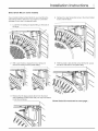
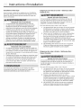
Installation Instructions
Electrical connection (non=Canada) =3 wire cord
3-wire receptacle
(NEMA type 10-30R)
" ---......
terminal cover
DO NOT
REMOVE
THIS SCREW
Failure to disconnect power source before servicing could
result in personal injury or even death.
1 Turn off power supply to outlet.
2 Remove the three screws securing the terminal block
access cover in the upper corner on the back of the
dryer.
3 Using an UNPLUGGED, UL-approved, 30 amp. power
cord, NEMA 10-30 type SRDT, attach the neutral (center
wire) conductor to the SILVER colored center terminal on
the terminal block. Tighten the screw securely.
line 1 - L1
BRASS terminal)
neutral - N
terminal)
line 2 - L2
BRASS terminal)
Terminal screws were shipped from the factory temporarily
attached inside the access cover.
4 Attach the remaining two power cord outer conductors
to the outer, BRASS colored terminals on the terminal
block. Tighten both screws securely.
Do not make a sharp bend or crimp wiring/conductor at
connections.
5 Reinstall the terminal block cover.
internal ground
(GREEN screw)
- route cord here
neutral
ELECTRICAL SHOCK HAZARD
Do not operate dryer without terminal cover in place. A
correctly installed terminal block cover also acts a qualified
strain relief for the power cord.
If moving dryer from a 4-wire system and installing it now
in a 3-wire system, move the internal ground wire from
the center terminal back to the GREEN screw under the
terminal block.

Installation Instructions
Electrical connection (non=Canada) - 4 wire cord
4-wire receptacle
(NEMA type 14-30R)
_._
.............. ., --_ Neutral
H_J 30AMP _G .... d. i(WHITEwire)
T NEMA14-30 _©_J(GREEN wire)
Failure to disconnect power source before servicing could
result in personal injury or even death.
1 Turn off power supply to outlet.
2 Remove the three screws securing the terminal block
access cover in the upper corner on the back of the
dryer.
3 Disconnect the internal (WHITE) dryer harness ground
wire from the (GREEN) ground screw next to the
terminal block.
4 Using an UNPLUGGED, UL-approved, 30 amp. power
cord, NEMA 14-30 type ST or SRDT, attach the ground
(GREEN) power cord wire to the cabinet with the
ground (GREEN) screw. Tighten the screw securely.
Terminal screws were shipped from the factory temporarily
attached inside the access cover.
5 Move the internal dryer harness ground (WHITE) wire
to the terminal block and attach it along with the neutral
(WHITE) power cord wire conductor to the center,
SILVER colored terminal on the terminal block. Tighten
the screw securely.
6 Attach the RED and BLACK power cord conductors
to the outer, BRASS colored terminals on the terminal
block. Tighten both screws securely.
terminal cover
"" _-::::_.__ccess cover
-- .. ":,_ ........... _:' screw
TTE .to \\--, _ /
"_ ) i__ _ DONOT
_' / c REMOVE
Iq __'_s#,'_'_J/ %_ THIS SCREW
access cover
" __ _ screw
-----, accesscover
_/ II/,i' " _#_ '' ,(_<_-_'_'_ screw
line 1 - L1
)
neutral - N
SILVER terminal)
line 2 - L2
'BRASS terminal)
move internal
ground wire to the
center terminal for
4-wire system
._ route cord here
neutral
ELECTRICAL SHOCK HAZARD
Do not make a sharp bend or crimp wiring/conductor at BLACK
connections, or RED
power wire
7 Reinstall the terminal block cover.
GREEN
ground screw
Do not operate dryer without terminal cover in place. A
correctly installed terminal block cover also acts a qualified
strain relief for the power cord.
WHITE
neutral wire
GREEN
ground wire
BLACK
or RED
power wire

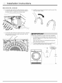
Installation Instructions
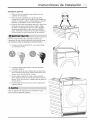
Direct Drain Kit (on some models)
If your model included a direct drain kit, you may follow the
instructions below to install it on your dryer for convenient
drainage of your dryer's condensed water.
1 Locate the redtubing and plastic fitting on the back of
the dryer.
4 Retrieve the clear tubing that came in the kit and install
it also onto the elbow.
With a pair of pliers, release the hose clamp and 5 With the plastic cable tie that came with the kit, secure
remove the tubing from the plastic fitting, the elbow and tubes to the plastic fitting.
Retrieve the 90 degree plastic elbow from the direct
drain installation kit that came with your dryer and install
itonto the red tubing.
\
\
\
Direct Drain Kit continued on next page...

Installation Instructions
Direct Drain Kit, continued
6 To route the drain tube to the leftof the dryer, secure
the tubewith the =P"clamp from the kit to the back of
the dryer with the cabinet screw shown below.
8 Install the hose hanger from the kit onto the end of the
hose and insert in drain.
7 To route the drain tube to the right of the dryer, route the
tube across the back of the dryer and snap it into the
'C" clips shown as below.
Follow these guidelines for proper drain hose installation:
1 The distance from the bottom of the drain tube sag to
the top of highest part of drain tube should be no more
than 20" (50 cm).
Drain tube may need to be shortened with scissors if
sag is greater than allowed.
2 The drain height location should be no more than 40"
(100 cm) above the bottom of the dryer feet.
O (50 cm) MAX
40"
(100crn)

Installation Instructions
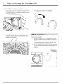
General installation
1 Use a carpenter's level to level your dryer front-to-back
and side-to-side.
2 Use adjustable pliers to adjust the leveling legs so the
dryer is level front-to-rear and side-to-side, and stable
corner-to-corner.
3 Press down on alternate corners and sides and feel for
the slightest movement. Adjust the appropriate leg(s)
so the dryer sits solidly on the floor on ALL four legs.
Keep the leveling leg extension at a minimum for best
performance of the dryer.
Be sure the power is off at a circuit breaker/fuse box before
plugging the power cord into an outlet.
4 Plug the power cord into a grounded outlet.
5 Turn on the power at the circuit breaker/fuse box.
6 Read the Use & Care Guide provided with the dryer. It
contains valuable and helpful information that will save
you time and money.
7 If you have any questions during initial operation,
please review the Avoid Service Checklist" in your Use
& Care Guide before calling for service.
8 Place these instructions in a location near the dryer for
future reference.
A wiring diagram is located next to the water container
behind the left cabinet panel.
I

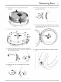
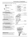
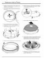
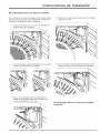
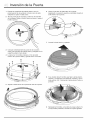
:::::Reversing Door
1 Protect flat work surface, such as top of dryer or floor
near dryer, with a soft cloth or towel.
2 Open dryer door and remove the two hinge screws.
Remove lower screw first, then upper screw.
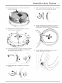
6 Release the door switch striker and move it to the
opposite location and reinstall. Set the inner door ring
aside.
7 Lift the inner lens and set it aside.
3 Gently place dryer door face down on flat, covered work
surface.
4 Locate the 12 screws (no. 1-12) on the inner door ring.
Remove and save these 12 screws.
I' ,k 1'
A i i I_
i
5 Separate inner door ring from the rest of the door.
8 If your model has 8 screws securing the outer lens in
place, remove and save them for later. Lift and rotate
the outer lens 180 ° . Lower the outer lens back in place.
9 Reinstall the 8 screws if removed in previous step. If no
screws were present, move to next step.

Reversing Door
10 Rotate inner lens 180 ° and place back into door
assembly.
14 Rotate the plastic latch cover 180° and snap it in place
around the door latch.
11 Reinstall inner door ring with 12 screws removed earlier.
12
13
_7
0
Gently pry the plastic latch cover from the front panel
and set it aside. Remove the 3 screws securing the door
latch and release the latch.
Rotate the latch 180 ° and reinstall it in the opposite
location.
15 While supporting the door, install the 2 hinge mounting
screws removed in first step. Attach the upper screw first
and then the lower one.
18 Close the door and test operation of hinge, strike and
latch.

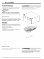
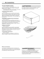
:: Accessories
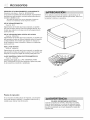
MATCHING STORAGE PEDESTAL*
White Pedestal - P/N EPWD200QSW
A storage pedestal accessory, specifically designed for this
dryer may be used to elevate the dryer for ease of use.
*Other colors may be available. Contact the source where you
purchased your dryer.
DIRECT DRAIN KiT
P/N DK11
Depending on the model you purchased, a direct draining
kit for your condensing dryer's water collection system may
have been included in the initial purchase of your dryer. If your
model did not include a direct draining kit, you may order one.
DRYER STACKING KiT
P/N STAC KIT24
Depending on the model you purchased, a kit for stacking this
dryer on top of matching washer may have been included in
the initial purchase of your dryer. If your model did not include
a stacking kit or you desire another stacking kit, you may
order one.
DRYING RACK
P/N 916093163
Depending on the model you purchased, a drying rack may
have been included in the initial purchase of your dryer. If
your model did not include a drying rack or you desire another
drying rack, you may order one.
UNIVERSAL APPLIANCE WRENCH
P/N 137019200
A UNIVERSAL APPLIANCE WRENCH is available to aid in
dryer/washer/pedestal feet adjustment.
Failure to use accessories manufactured by or approved
by the manufacturer could result in personal in ury,
property damage or damage to the dryer.
Replacement parts:
If replacements parts are needed for your dryer, contact the
source where you purchased your dryer or refer to your Use
and Care Guide for more information.
Label all wires prior to disconnection when servicing controls.
Wiring errors can cause improper and dangerous operation.
Verify proper operation after servicing.
Page is loading ...
Page is loading ...
Page is loading ...
Page is loading ...
Page is loading ...
Page is loading ...
Page is loading ...
Page is loading ...
Page is loading ...
Page is loading ...
Page is loading ...
Page is loading ...
Page is loading ...
Page is loading ...
Page is loading ...
Page is loading ...
Page is loading ...
Page is loading ...
Page is loading ...
Page is loading ...
Page is loading ...
Page is loading ...
Page is loading ...
Page is loading ...
Page is loading ...
Page is loading ...
Page is loading ...
Page is loading ...
Page is loading ...

www electrolux com,'shop
o
od
o
ca
d,
oo
cD
o'3
T'-
(€
-
 1
1
-
 2
2
-
 3
3
-
 4
4
-
 5
5
-
 6
6
-
 7
7
-
 8
8
-
 9
9
-
 10
10
-
 11
11
-
 12
12
-
 13
13
-
 14
14
-
 15
15
-
 16
16
-
 17
17
-
 18
18
-
 19
19
-
 20
20
-
 21
21
-
 22
22
-
 23
23
-
 24
24
-
 25
25
-
 26
26
-
 27
27
-
 28
28
-
 29
29
-
 30
30
-
 31
31
-
 32
32
-
 33
33
-
 34
34
-
 35
35
-
 36
36
-
 37
37
-
 38
38
-
 39
39
-
 40
40
-
 41
41
-
 42
42
-
 43
43
-
 44
44


Electrolux EIED200QSW00 Installation guide
- Category
- Tumble dryers
- Type
- Installation guide
- This manual is also suitable for
Ask a question and I''ll find the answer in the document
Finding information in a document is now easier with AI
in other languages
Related papers
-
Electrolux EFDE210TIW01 Installation guide
-
Electrolux EIED200QSW Installation guide
-
-
Electrolux EFDE210TIS Installation guide
-
-
Electrolux EIMED55IMB3 Installation guide
-
Electrolux EFDE210TIS Operating instructions
-
Electrolux ELFE4222AW Installation guide
-
Electrolux EIMED60JMB0 Installation guide
-
Other documents
-
Kenmore 81942 Installation guide
-
Maytag MED9600SQ0 User manual
-
Frigidaire FAQG7001LW0 Installation guide
-
Crosley CDEC750KW0 Installation guide
-
Kenmore Elite 41791100003 Installation guide
-
-
Frigidaire GLGQ2170KS0 Installation guide
-
-
-