Electrolux EIMED55IMB3 Installation guide

Category
Electric laundry dryers
Type
Installation guide
important Safety instructions
Recognize safety symbols, words and
labels
Safety items throughout this manual are labeled
with a WARNING or CAUTION based on the risk
type as described:
WARNING This symbol alerts you to situa-
tions that may cause serious body
harm, death or property damage.
CAUTION This symbol alerts you to situa-
tions that may cause bodily injury
or property damage.
[ WARNING - RISK OF F RE
Read all of the following _ structions before installing and using this appliance:
Destroy the carton and plastic bags after the dryer is unpacked. Children might use them for play. Cartons
covered with rugs, bedspreads, or plastic sheets can become airtight chambers causing suffocation. Place
all materials in a garbage container or make materials inaccessible to children.
Clothes dryer installation and service must be performed by a qualified installer, service agency or the
gas supplier.
, Install the clothes dryer according to the manufacturer's instructions and local codes.
The electrical service to the dryer must conform with local codes and ordinances and the latest edition
of the National Electrical Code, ANSI/NFPA 70, or in Canada, the Canadian electrical code C22.1 part 1.
The gas service to the dryer must conform with local codes and ordinances and the latest edition of
the National Fuel Gas Code ANSI Z223.1, or in Canada, CAN/ACG B149.1-2000. An individual manual
shut-off valve must be installed within 6 ft (1.83 m) of the dryer in accordance with the National Fuel
Gas Code, ANSI Z223.1/NFPA 54.
The dryer is designed under ANSI Z 21.5.1 or ANSI/UL 2158 - CAN/CSA C22.2 No. 112 (latest edi-
tions) for HOME USE only. This dryer is not recommended for commercial applications such as restau-
rants, beauty salons, etc.
Do not install a clothes dryer with flexible plastic or flexible foil venting material. Flexible venting mate-
rials are known to collapse, be easily crushed and trap lint. These conditions will obstruct clothes dryer
airflow and increase the risk of fire.
Do not stack a dryer on top of washer already installed on pedestal. Do not stack washer on top of
dryer. Do not stack washer on top of another washer.
The instructions in this manual and all other literature included with this dryer are not meant to cover
every possible condition and situation that may occur. Good safe practice and caution MUST be ap-
plied when installing, operating and maintaining any appliance.
TaMe of contents
Important Safety Instructions ......................................... 2
Installation Requirements ............................................ 3-9
Installed Dimensions ...................................................... 9
Installation Instructions ........................................... 10-18
Reversing Door ........................................................ 19-23
Options ......................................................................... 24
WHAT TO DO iF YOU SMELL GAS:
Do not try to light any appliance.
Do not touch any electrical switch; do not use
any phone in your building.
Clear the room, building or area of all occupants.
Immediately call your gas supplier from a neigh-
bor's phone. Follow the gas supplier's instructions.
If you cannot reach your gas supplier, call the fire
department.
Save these instructions for
future reference.
©2011 Electrolux Major Appliances All rights reserved.
Installation Requirements
Please read and save this guide
Thank you for choosing Electrolux, the new
premium brand in home appliances. These
Installation Instructions are part of our commitment
to customer satisfaction and product quality
throughout the life of your new appliance.
For toll-free telephone support in the U.S.: 1-877-
4ELECTROLUX (1-877-435-3287) and in Canada:
1-800-265-8352.
For online support and product information visit
www.electroluxappliances.com.
PreqnstaHation requirements
Tools and materials needed for installation:
or
or
Adjustable Phillips, straight, & Adjustable Universal wrench
pliers square bit screwdrivers wrench supplied with
matching washer
4 inch, rigid metal or
semi-rigid metal exhaust duct work
3-wire or 4-wire
240 volt cord kit
(electric dryer)
Pipe wrench LP-resistant Carpenter's level External
for gas thread tape vent hood
supply (for natural gas ..
or LP supply)
'J2".PTunionflare
4 in, gas line adapters (x2) and
(10.2 cm) shutoff valve flexible gas supply line Metal foil tape
clamp (gas dryer) (gas dryer) (not duct tape)
Installation Requirements
Electrical system requirements
ELECTRICAL REQUIREMENTS FOR ELECTRIC
DRYER:
CIRCUIT - Individual 30 amp. branch circuit
fused with 30 amp. time delay fuses or circuit
breakers. Use separately fused circuits for
washer and dryer. DO NOT operate a washer
and a dryer on the same circuit.
POWER SUPPLY - 3-wire or 4-wire, 240 volt,
single phase, 60 Hz, Alternating Current.
4-WIRE POWER SUPPLY CORD KIT (not supplied)
4-wire receptacle
(NEMA type 14-30R)
The dryer MUST employ a 4-conductor power
supply cord NEMA 14-30 type SRDT or ST (as
required) rated at 240 volt AC minimum, 30 amp,
with 4 open end spade lug connectors with
upturned ends or closed loop connectors and
marked for use with clothes dryers. For 4-wire
cord connection instructions see ELECTRICAL
CONNECTIONS FOR A 4-WIRE SYSTEM.
OUTLET RECEPTACLE - NEMA 10-30R or NEMA
14-30R receptacle to be located so the power
supply cord is accessible when the dryer is in the
installed position.
GROUNDING CONNECTION - See "Grounding
requirements" in Electrical Installation section.
3-WIRE POWER SUPPLY CORD KIT (not supplied)
3-wire receptacle
(NEMA type 10-30R)
The dryer MUST employ a 3-conductor power
supply cord NEMA 10-30 type SRDT rated at
240 volt AC minimum, 30 amp, with 3 open
end spade lug connectors with upturned ends
or closed loop connectors and marked for use
with clothes dryers. For 3-wire cord connection
instructions see ELECTRICAL CONNECTIONS
FOR A 3-WIRE SYSTEM.
ELECTRICAL REQUIREMENTS FOR GAS DRYER:
CIRCUIT - Individual, properly polarized and
grounded 15 amp. branch circuit fused with 15
amp. time delay fuse or circuit breaker.
POWER SUPPLY - 2-wire, with ground, 120 volt,
single phase, 60 Hz, Alternating Current.
POWER SUPPLY CORD - The dryer is equipped
with a 120 volt 3-wire power cord.
GROUNDING CONNECTION - See "Grounding
requirements" in Electrical Installation section.
Grounding type
wall receptacle
Donot, under "_
any circumstances,
cut, remove,
or bypassthe
grounding prong. /
Powercord with
3-prong grounded plug
Installation Requirements
Gas supply requirements
1. Installation MUST conform with local codes, or
in the absence of local codes, with the National
Fuel Gas Code, ANSI Z223.1 (latest edition).
2. The gas supply line should be 1/2 inch (1.27
cm) pipe.
3. If codes allow, flexible metal tubing may be
used to connect your dryer to the gas supply
line. The tubing MUST be constructed of
stainless steel or plastic-coated brass.
4. The gas supply line MUST have an individual
shutoff valve installed in accordance with the
B149.1, Natural Gas and Propane Installation
Code.
5. A 1/8 inch (0.32 cm) N.RT. plugged tapping,
accessible for test gauge connection, MUST
be installed immediately upstream of the gas
supply connection to the dryer.
6. The dryer MUST be disconnected from the
gas supply piping system during any pressure
testing of the gas supply piping system at test
pressures in excess of 1/2 psig (3.45 kPa).
7. The dryer MUST be isolated from the gas supply
piping system during any pressure testing of the
gas supply piping system at test pressures equal
to or less than 1/2 psig (3.45 kPa).
8. Connections for the gas supply must comply
with the Standard for Connectors for Gas
Appliances, ANSI Z21.24.
Exhaust system requirements
Use only 4 inch (102 mm) diameter (minimum) rigid
or flexible metal duct and approved vent hood
which has a swing-out damper(s) that open when
the dryer is in operation. When the dryer stops,
the dampers automatically close to prevent drafts
and the entrance of insects and rodents. To avoid
restricting the outlet, maintain a minimum of 12
inches (30.5 cm) clearance between the vent hood
and the ground or any other obstruction.
Correct
!1
incorrect
The following are specific requirements
for proper and safe operation of your
dryer.
If your present system _smade up of plastic duct
or metal foil duct, replace itwith a rigid or semi-
rigid metal duct. Also, ensure the present duct is
free of any lint prior to installing dryer duct.
Installation Requirements
Exhaust system requirements, continued
The dryer must be connected to an exhaust
outdoors. Regularly inspect the outdoor exhaust
opening and remove any accumulation of lint
around the outdoor exhaust opening and in the
surrounding area.
0
1
2
3
4
MAXIMUM LENGTH
of 4" (102mm) Rigid Metal Duct
VENT HOOD TYPE
(Preferred)
4"
(10.2cm) Iouvered
125 ft. (38.10m)
115 ft. (35.05m)
105 ft. (32.00m)
95 ft. (28.96m)
85 ft. (25.91 m)
2.5"
(6.35cm)
110 ft. (33.53m)
100 ft. (30.48m)
90 ft. (27.43m)
80 ft. (24.38m)
70 ft. (21.34m)
EXHAUST DIRECTION
Directional exhausting can be accomplished by
installing a quick-turn 90° dryer vent elbow directly
to exhaust outlet of dryer. Dryer vent elbows are
available through your local parts distributor or
hardware store.
See also CLEARANCE
REQUIREMENTS on the
next page.
Installation Requirements
Exhaust system requirements, continued
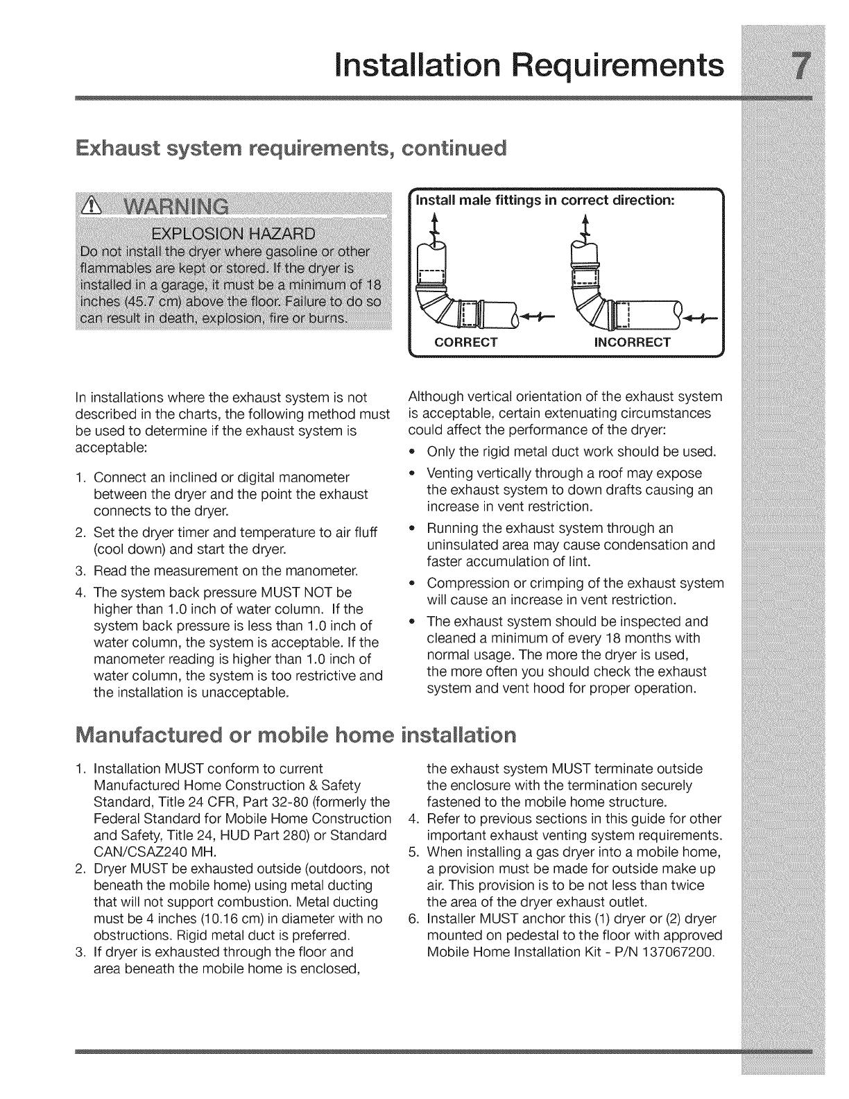
Install male fittings in correct direction:
CORRECT INCORRECT
In installations where the exhaust system is not
described in the charts, the following method must
be used to determine if the exhaust system is
acceptable:
.
.
3.
4.
Connect an inclined or digital manometer
between the dryer and the point the exhaust
connects to the dryer.
Set the dryer timer and temperature to air fluff
(cool down) and start the dryer.
Read the measurement on the manometer.
The system back pressure MUST NOT be
higher than 1.0 inch of water column. If the
system back pressure is less than 1.0 inch of
water column, the system is acceptable. If the
manometer reading is higher than 1.0 inch of
water column, the system is too restrictive and
the installation is unacceptable.
Although vertical orientation of the exhaust system
is acceptable, certain extenuating circumstances
could affect the performance of the dryer:
Only the rigid metal duct work should be used.
Venting vertically through a roof may expose
the exhaust system to down drafts causing an
increase in vent restriction.
Running the exhaust system through an
uninsulated area may cause condensation and
faster accumulation of lint.
Compression or crimping of the exhaust system
will cause an increase in vent restriction.
The exhaust system should be inspected and
cleaned a minimum of every 18 months with
normal usage. The more the dryer is used,
the more often you should check the exhaust
system and vent hood for proper operation.
Manufactured or mobile home installation
1. Installation MUST conform to current
Manufactured Home Construction & Safety
Standard, Title 24 CFR, Part 32-80 (formerly the
Federal Standard for Mobile Home Construction
and Safety, Title 24, HUD Part 280) or Standard
CAN/CSAZ240 MH.
2. Dryer MUST be exhausted outside (outdoors, not
beneath the mobile home) using metal ducting
that will not support combustion. Metal ducting
must be 4 inches (10.16 cm) in diameter with no
obstructions. Rigid metal duct is preferred.
3. If dryer is exhausted through the floor and
area beneath the mobile home is enclosed,
the exhaust system MUST terminate outside
the enclosure with the termination securely
fastened to the mobile home structure.
4. Refer to previous sections in this guide for other
important exhaust venting system requirements.
5. When installing a gas dryer into a mobile home,
a provision must be made for outside make up
air. This provision is to be not less than twice
the area of the dryer exhaust outlet.
6. Installer MUST anchor this (1) dryer or (2) dryer
mounted on pedestal to the floor with approved
Mobile Home Installation Kit - P/N 137067200.
installation Requirements
Clearance requirements
INSTALLATION IN A RECESS OR CLOSET
1. A dryer installed in a bedroom, bathroom,
recess or closet, MUST be exhausted outdoors.
2. No other fuel burning appliance shall be
installed inthe same closet as the gas dryer.
3. Your dryer needs the space around it for proper
ventilation.
DO NOT install your dryer in a closet with a solid
door.
.
Closet door ventilation required: A minimum
of 120 square inches (774.2 cm 2)of opening,
equally divided at the top and bottom of the
door, is required. Openings should be located
3 inches (7.6 cm) from bottom and top of door.
Openings are required to be unobstructed
when a door is installed. A Iouvered door with
equivalent air openings for the full length of the
door is acceptable.
3"
i (7-6cm)
3"
i(7,6cm)
closet door
f
60 sq. in.
(387.1cm 2)
MINIMUM INSTALLATION CLEARANCES -Inches (cm)
SIDES REAR TOP FRONT
Alcove 0" (0 cm) 0" (0 cm)* 0" (0 cm) n/a
Under-
0" (0 cm) 0" (0 cm)* 0" (0 cm) n/a
Counter
Closet 0" (0 cm) 0" (0 cm)* 0" (0 cm) 1" (2.5 cm)
For other than straight back venting, a quick-turn 90°
dryer vent elbow must be installed to achieve 0" (0 cm)
ii
ii
II
0"41 I#
(Ocm) ol
Installation Requirements
Dryer dimensions
53.5" (136 cm)*
to clear open door
freestand dryer
on floor
floor line
31.5" (79.5 cm)*
to front of closed door
..J
m
dryer mounted on
optional pedestal
53.5" (136 cm)*
to clear open door
floor line
31.5" (79.5 cm)*
to front of c osed door
75.75"
(192.5 cm)
*Connection of water inlet hose on steam dryer adds 3/4 in. (2 cm) to installation depth.
_Power supply cord length on gas dryer approximately 60 inches (152.5 cm).
Hot and cold inlet hose length on washer approximately 48.5 inches (123 cm).
3Drain hose length on washer approximately 59 inches (150 cm).
4Power supply cord length on washer approximately 60 inches (152.5 cm).
t
38,0"
(96.5 cm)
27.0" --
(68.5 cm)
53.25"
(135.5 cm)
gas supply
Dpe on rear
of gas unit
l--
17.0"
(43 cm)
electrical
supply on
rear of unit _
centerline
height for
rear vent
19.0"
(48 cm)
water supply
connection on
rear of unit 2 \
\
gas supply
pipe on rear
of gas unit
39.0"
(99 cm)
drain hose on
rear of uniP
electrical
supply on
rear of unit4
centerline
height for
rear vent
)ower cord on
rear of unit 4
41.0"
(105 cm)
Installation Instructions
Electrica installation
The following are specific requirements for proper
and safe electrical installation of your dryer. Failure
to follow these instructions can create electrical
shock and/or a fire hazard.
Grounding requirements - Emectdc dryer (USA}
For a grounded, cord-connected dryer:
1. The dryer MUST be grounded. In the event of
a malfunction or breakdown, grounding will
reduce the risk of electrical shock by a path of
least resistance for electrical current.
2. After you purchase and install a 3 wire or 4
wire power supply cord having an equipment-
grounding conductor and a grounding plug
that matches your wiring system, the plug
MUST be plugged into an appropriate, copper
wired receptacle that is properly installed and
grounded in accordance with all local codes and
ordinances. If in doubt, call a licensed electrician.
3. DO NOT modify the plug you've installed on
this appliance. If it will not fit the outlet, have a
proper outlet installed by a qualified electrician.
For a permanently connected dryer:
1. The dryer MUST be connected to a grounded
metal, permanent wiring system; or an
equipment grounding conductor must be run
with the circuit conductors and connected to
the equipment-grounding terminal or lead on
the appliance.
Installation Instructions
Grounding requirements o
Grounding type
wall receptacle
/
Do not, under
any circumstances,
cut, remove,
or bypass the
grounding prong.
Power cordwith
3-
Electric dryer (Canada}
For a grounded, cord-connected dryer:
1. The dryer MUST be grounded. In the event of
a malfunction or breakdown, grounding will
reduce the risk of electrical shock by a path of
least resistance for electrical current.
.
.
Since your dryer is equipped with a power
supply cord having an equipment-grounding
conductor and a grounding plug, the plug must
be plugged into an appropriate outlet that is
properly installed and grounded in accordance
with all local codes and ordinances. If in doubt,
call a licensed electrician.
DO NOT modify the plug provided with this
appliance. If it will not fit the outlet, have a
proper outlet installed by a qualified electrician.
Gas dryer (USA and Canada}
1. The dryer is equipped with a three-prong
(grounding) plug for your protection against
shock hazard and should be plugged
directly into a properly grounded three-prong
receptacle.
2. The plug must be plugged into an appropriate
outlet that is properly installed and grounded in
accordance with all local codes and ordinances.
If in doubt, call a licensed electrician.
3. DO NOT modify the plug provided with this
appliance. If it will not fit the outlet, have a
proper outlet installed by a qualified electrician.
Installation Instructions
Electrical connection (non-Canada) o 3 wire cord
3-wire receptacle
(NEMA type 10-30R)
.
2.
.
.
.
.
Turn off power supply to outlet.
Remove the screw securing the terminal block
access cover in the lower corner on the back of
the dryer.
Install a UL-approved strain relief according
to the power cord/strain relief manufacturer's
instructions in the power cord entry hole below
the access panel. At this time, the strain relief
should be loosely in place.
Thread an UNPLUGGED, UL-approved, 30 amp.
power cord, NEMA 10-30 type SRDT, through the
strain relief.
Attach the power cord neutral (center wire)
conductor to the SILVER colored center
terminal on the terminal block. Tighten the
screw securely.
Attach the remaining two power cord outer
conductors to the outer, BRASS colored
terminals on the terminal block. Tighten both
screws securely.
___ Install
........... UL-approved
................ _/ strain relief hem
Terminal screw
recovery slot
DO NOTremove
internal ground in
a 3-wire system!!
Neutral
terminal
.
Follow manufacturer's guidelines for firmly
securing the strain relief and power cord.
8. Reinstall the terminal block cover.
Installation instructions
Electrica
connection (non-Canada) - 4 wire cord
4-wire receptacle
(NEMA type 14-30R)
-- Neutral
WHITE wire)
1. Turn off power supply to outlet.
2. Remove the screw securing the terminal block
access cover in the lower corner on the back of
the dryer.
3. Install a UL-approved strain relief according
to the power cord/strain relief manufacturer's
instructions in the power cord entry hole below
the access panel. At this time, the strain relief
should be loosely in place.
4. Thread an UNPLUGGED, UL-approved, 30
amp. power cord, NEMA 14-30 type ST or
SRDT, through the strain relief.
5. Disconnect the internal (WHITE) dryer harness
ground wire from the (GREEN) ground screw
next to the terminal block.
6. Attach the ground (GREEN) power cord wire
to the cabinet with the ground (GREEN) screw.
Tighten the screw securely.
7. Move the internal dryer harness ground
(WHITE) wire to the terminal block and attach
it along with the neutral (WHITE) power cord
wire conductor to the center, SILVER colored
terminal on the terminal block. Tighten the
screw securely.
8. Attach the RED and BLACK power cord
conductors to the outer, BRASS colored
terminals on the terminal block. Tighten both
screws securely.
_ _ Accesscover
_lj screw
Line 2
Neutral
\_ \'_ ---------- (BRASSterminal)
\
_ Internal ground
(GREEN screw)
Install
UL-approved
strain relief here
Terminal screw
recovery slot
Move internal ground (WHITE)
wire to neutral (SILVER)
terminal for 4-wire system.
|
'\\./
GREEN
ground screw
Neutral
terminal
WHITE
neutral wire
9. Follow manufacturer's guidelines for firmly
securing the strain relief and power cord.
10. Reinstall the terminal block cover.
GREEN
ground wir,
BLACKor
REDpower wire
BLACK
or RED
power wire
installation instructions
Gas connection
1. Remove the shipping cap from gas pipe at the 3.
rear of the dryer.
Open the shutoff valve in the gas supply line to
allow gas to flow through the pipe. Wait a few
minutes for gas to move through the gas line.
2_
Connect a 1/2 inch (1.27 cm) I.D. semi-rigid or
approved pipe from gas supply line to the 3/8
inch (0.96 cm) pipe located on the back of the
dryer. Use a 1/2 inch to 3/8 inch (1.27 cm to
0.96 cm) reducer for the connection. Apply an
approved thread sealer that is resistant to the
corrosive action of liquefied gases on all pipe
connections.
Manual GAS FLOW
Shutoff Flare _ Flare
Valve Union Union
_-los t
i Flexible Inlet Pipe on
Open Connector Back of Dryer
All connections must be wrench-tightened
Shutoff Valve-
Open position
.
Check for gas system leaks with a manometer.
If a manometer is not available, test all
connections by brushing on a soapy water
solution.
Installation instructions
Water connection (Steam Model only}
WATER SUPPLY REQUIREMENTS
Cold water faucet MUST be installed within 42
inches (107 cm) of your dryer's water inlet. The
faucet MUST be 3/4 inch (1.9 cm) with thread-
ing for laundry hose connection. Water pressure
MUST be between 30 and 120 psi. Your water
department can advise you of your water pressure.
.
2.
Turn off COLD water supply to washer,
Remove COLD inlet hose from COLD water
supply and inspect for rubber washer. Replace
washer if it is torn or worn out.
RUBBER WASHER
MUST BEPRESENT
AND UNDAMAGED
J
COLD INLET HOSE
TO WASHER
3. Momentarily turn on COLD supply and run
some water into a bucket or container to clear
any contaminants in the line.
4. Remove hose kit from dryer drum and inspect
hose couplings for proper placement of rubber
washers.
RUBBER WASHERS
MUST BE PRESENT
installation instructions
Water connection, con't Stea Model only}
.
If your installation has room for the COLD
water supply to accept the "Y" connector
directly, thread the "Y" connector to the COLD
water supply and snug it by hand; then tighten
it another 2/3 turn with pliers.
6. If there is not room to install the "Y" connector
directly, thread the short extension hose on to
the COLD water supply and snug it by hand;
then tighten it another 2/3 turn with pliers.
7. Thread the "Y" connector to the short
extension hose and snug it by hand; then
tighten it another 2/3 turn with pliers.
8. Connect the COLD inlet hose for the washer
to the "Y" connector and snug it by hand; then
tighten it another 2/3 turn with pliers.
9. Connect the straight end of the long hose from
the kit to the other outlet on the "Y" connector
and snug it by hand. Connect the hose's 90°
coupling to the brass water inlet on the back
of the dryer and snug it by hand. Tighten each
connection of the dryer inlet hose another 2/3
turn with pliers.
10. Turn on the water and check for leaks at all
connections.
DIRECT CONNECTION
OR WITH EXTENSION
WATER INLETON_RYEF
COLD WATER SUPPLY
HOSE TO WASHER
Installation instructions
Genera installation
.
.
.
Connect the exhaust duct to the outside exhaust
system (see pages 5 through 7). Use of a 4" (102
mm) clamp (item A) is recommended to connect
the dryer to the exhaust vent system. Use metal
foil tape to seal all other joints.
Carefully slide the dryer to its final position.
Adjust one or more of the legs until the dryer is
resting solidly on all four legs. Place a level on
top of the dryer. The dryer MUST be level and
resting solidly on all four legs. Rock alternating
corners to check for stability. Remove and
discard door tape.
.
5.
Plug the power cord into a grounded outlet.
Turn on the power at the circuit breaker/fuse
box.
Read the Use & Care Guide provided with ..............
the dryer. It contains valuable and helpful
information that will save you time and money.
6. See the next page about performing a brief,
helpful "Installation Cycle" for your new dryer. .............................................................
7. If you have any questions during initial
operation, please review the "Avoid Sewice
Checklist" in your Use & Care Guide before
calling for service.
8. Place these instructions in a location near the
dryer for future reference.
Power_
3-prong grounded p!ug
Installation Instructions
Pe orming Installation Cycle
With your dryer in final location, perform an Installation Cycle to assist in proper installation.
If your dryer hasthis console:
2a
2b
1 3 4
1. Empty dryer's drum and close door.
2. After you plug in the dryer the first time: wake up the
dryer by pressing any button, rotate cycle knob to
cycle one up from lower right position (1), press the
start button (3) and then the cancel button (4).
3. Wake up the dryer again by pressing any button, then
immediately and simultaneously press and hold but-
tons 2a and 2b for 5 seconds, or until the LCD display
changes.
4. The LCD window will display II'ISTRLCEICLEand show
estimated time of cycle completion. Press the start
button. The Installation Cycle will automatically per-
form various diagnostic routines. At cycle completion,
the LCD window may display II'ISTRLPR.£SI,meaning
your new dryer is properly installed and ready for use.
If it prompts an action such as .SERVICECORD,NOGR.S
or CRLL.SERVICE877 figs 9287, review the installation
steps and make the necessary corrections before you
attempt to use the dryer.
5. Your dryer will exit the installation Cycle and return to
normal operation the next time you wake it up.
6. Please read the Use & Care Guide and enjoy your new
premium dryer!
If your dryer has this console:
Oo
_O
@
1. After you plug in the dryer the first time: wake up the
dryer by pressing any button and follow the prompts
on the LCD User Interface, including language selec-
tion.
2. The Installation Cycle will automatically test for correct
cord connection (on electric models), presence of
gas supply (on gas models) and free flow of exhaust
vent. At cycle completion, the LCD user interface
may display II'ISTRLPR.£St,meaning your new dryer is
properly installed and ready for use. If it prompts an
action such as .SERVICECORD,NOGR.Sor CRLL.SERVICE
877 figs 9287, review the installation steps and make
the necessary corrections before you attempt to use
the dryer.
3. Your dryer will exit the installation Cycle and return to
normal operation the next time you wake it up.
4. Please read the Use & Care Guide and enjoy your new
premium dryer!
Reversing Door
Preparing to
1
2
3
4
reverse door swing
Be sure you have adequate swing area before reversing door.
You will need a screw driver with a #2 square bit.
Protect flat work surface, such as top of dryer or floor near dryer,
with a soft cloth or towel.
Be sure dryer is unplugged from power source!
Tools needed:
Screwdrivers with
#2 square &
straight bit
Removing door and hardware
A) Removing Trim Ring
1 Open door to 90 degree angle.
2 Remove and save trim plug and long,
course-thread, panhead screw.
B) Removing Door from Hinge
1 Reopen door to 90 degree angle.
2 Remove 4 long, course-thread, counter-sunk
hinge screws from door.
3 Close door.
4 Rotate door trim approximately 3A"counter-
clockwise and pull ring away from door.
\
3
4
While supporting the weight of the door
with both hands, separate the door from the
hinge.
Gently place door face down on flat, covered
work surface.
Reversing Door
Reversing door and hardware
C) Removing Hinge from Front Panel
1 With the hinge in open position, remove 2
short, course-thread, panhead screws on
hinge plate.
Remove 3 short, fine-thread, counter-sunk
screws in hinge side.
D) Reversing Hardware on Front Panel
1 Remove 2 short, course-thread, panhead
screws from striker and 2 plastic hole plugs.
Rotate striker and move to opposite
opening. Attach with 2 short, course-thread,
panhead screws.
3 Install plastic hole plugs.
E) Reattaching Hinge to Front Panel
1 Rotate the hinge and move it to the opposite
opening. Use the side locating pins to align the
hinge and install 1 short, fine-thread, counter-
sunk screw in the center hole of hinge side.
2 Install the other 2 short, fine-thread, counter-
sunk screws in the upper and lower holes of
hinge side.
3 Install 2 short, course-thread, panhead
screws through hinge plate.
Reversing Door
F) Removing Striker Plate
1 Remove 2 long, course-thread, counter-sunk
screws and latch plate.
2 Set the latch plate to the side for later.
G) Removing Latch Indicator
\
2
Insert flat blade screwdriver into open slot of
latch indicator.
Gently pry upward to release tab.
H) Removing Hole Plug
1 Insert flat blade screwdriver into open slot of
hole plug.
2 Gently pry upward to release tab.
3 Pull the hole plug out and set it aside.
3 Pull the indicator out and set it aside.
  • Page 1 1
  • Page 2 2
  • Page 3 3
  • Page 4 4
  • Page 5 5
  • Page 6 6
  • Page 7 7
  • Page 8 8
  • Page 9 9
  • Page 10 10
  • Page 11 11
  • Page 12 12
  • Page 13 13
  • Page 14 14
  • Page 15 15
  • Page 16 16
  • Page 17 17
  • Page 18 18
  • Page 19 19
  • Page 20 20
  • Page 21 21
  • Page 22 22
  • Page 23 23
  • Page 24 24
  • Page 25 25
  • Page 26 26
  • Page 27 27
  • Page 28 28
  • Page 29 29
  • Page 30 30
  • Page 31 31
  • Page 32 32
  • Page 33 33
  • Page 34 34
  • Page 35 35
  • Page 36 36
  • Page 37 37
  • Page 38 38
  • Page 39 39
  • Page 40 40
  • Page 41 41
  • Page 42 42
  • Page 43 43
  • Page 44 44
  • Page 45 45
  • Page 46 46
  • Page 47 47
  • Page 48 48
  • Page 49 49
  • Page 50 50
  • Page 51 51
  • Page 52 52
  • Page 53 53
  • Page 54 54
  • Page 55 55
  • Page 56 56
  • Page 57 57
  • Page 58 58
  • Page 59 59
  • Page 60 60
  • Page 61 61
  • Page 62 62
  • Page 63 63
  • Page 64 64
  • Page 65 65
  • Page 66 66
  • Page 67 67
  • Page 68 68
  • Page 69 69
  • Page 70 70
  • Page 71 71
  • Page 72 72
  • Page 73 73
  • Page 74 74
  • Page 75 75
  • Page 76 76

Electrolux EIMED55IMB3 Installation guide

Category
Electric laundry dryers
Type
Installation guide

Ask a question and I''ll find the answer in the document

Finding information in a document is now easier with AI