Page is loading ...


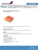
1. Heatsink
· Dimensions(mm) : 126(L) x 110(W) x 45(H)
· Weight(g) : 290
· Materials
- Dissipation Fins : Pure Aluminum
- Base: Pure Copper
- Heatpipe : Pure Copper
1
Cautions on Use and Installation
Specifications
Components
Disclaimer) Zalman Tech Co., Ltd. is not responsible for any damages due to external causes,
including but not limited to, improper use, problems with electrical power, accident,
neglect, alteration, repair, improper installation, or improper testing.
By installing this product on a VGA (Video Graphics Array) card, two PCI slots adjacent to the PCIe (or AGP)
slot occupied by the VF2000 will become unusable.
The product CANNOT be installed on Matrox VGA cards, NVIDIA PCX 5*** , NVIDIA Geforce 6600 AGP
Series, Geforce 7600/7900 AGP Series, and ATI Radeon 9550/9600 Series, any cards with less than four
installation holes, and any cards with a diagonal installation hole distance that is not 75.2mm.
To properly install the cooler onto a CPU, please remove the motherboard from the case and install the
VF2000 so that the ends of the cooler’s heatpipes are directed towards the case’s exhaust fan.
If the VGA card and/or its components interfere with the installation of this product, then stop the installation,
refer to the list of compatible VGA cards or motherboards at Zalman’s website, and install this product with one
of the compatible VGA cards or motherboards.
If this product is to be installed on a recently released VGA card, please check for compatibility at Zalman’s
website first.
The use of an exhaust fan positioned on the rear side of the case is recommended for enhanced product performance.
Check the components list and condition of the product before installation. If any problem is found, contact the
retailer to obtain a replacement.
Do not ingest the Thermal Grease, and avoid its contact with skin and eyes. If contact is made with skin, wash
off with water. If ingested or any irritation persists, seek medical attention.
Excessive force exerted on the cooler may cause damage to the cooler and/or system.
Avoid inserting objects into the fan while it is in operation.
Zalman is not responsible for any damages caused by overclocking.
During transportation of the system, the cooler must be removed. Zalman is not responsible for any damages
that occur during the transport of a system.
Product design and specifications may be revised to improve quality and performance.
1.
2.
3.
4.
5.
6.
7.
8.
9.
10.
11.
12.
13.
2. Fan
· Dimensions(mm) : 92(L) x 92(W) x 15(H)
· Bearing Type : 2 Ball-Bearing
· Speed (with Fan Mate 2)
- 1400rpm ± 10%(5V, Quiet Mode)
- 2350rpm ± 10%(12V, Performance Mode)
· Noise Level (with Fan Mate 2)
- 19dBA ± 10%(5V, Quiet Mode)
- 29dBA ± 10%(12V, Performance Mode)
1. Common Components
①
One (1) VF2000 Cooler
②
Four (4) Springs
③
Four (4) Fixing Nuts
④
Two (2) Thermal Grease
⑤
One (1) PVC Washer Plate
⑥
One (1) Fan Controller (FAN MATE 2)
⑦
One (1) Cable for FAN MATE 2
⑧
One (1) Double-Sided Tape (to attach FAN MATE 2)
⑨
One (1) User’s Manual
2. VGA Components
⑩
Eight (8) RAM Heatsinks
⑪
Four (4) Nipples A
⑫
Four (4) Rubber Rings A
3. CPU Components
⑬
Two(2) Intel Socket 775 Clips A
⑭
Two(2) AMD Socket AM2/AM2+Clips B
⑮
Four (4) Bolts
⑯
Four (4) Nipples B
⑰
Four (4) Rubber Rings B
①
⑤⑥ ⑦ ⑧ ⑨
⑩⑪⑫
⑬⑭⑮⑯⑰
②③④

2
Explode View (Usage as VGA Cooler)

3
Explode View (Usage as CPU Cooler)
Intel Socket 775
Intel Socket 775
AMD Socket AM2/AM2+

4
Installation Procedure (Usage as VGA Cooler)
4. Spring Insertion on the Fixing Nut
Slowly turn the Spring in counter clockwise motion so that theSpring is correctly
attached to the Fixing Nut.
Note 1)
The ends of the Springs are of different diameters. Install the Spring end with the
smaller diameter on the Fixing Nut as shown in the diagram.
Note 2)
Make sure that the Spring is installed perpendicularly and not leaning to one
side.
1. VGA RAM Heatsink Attachment
Remove the film from the Thermal Tapes on the bottom
of the RAM Heatsinks and attach the Heatsinks on the
VGA RAM.
Note 1)
If Thermal Grease or other residue remains on the RAM,
then the Thermal Tapes will not stick. Clean the surface of
the RAM with acetone or alcohol before attaching the
RAM Heatsinks.
Note 2)
The bonding strength of the Thermal Tapes reaches 90%
after 24 hours of curing. Do not exert excessive force on
the RAM Heatsinks during this period.
Note 3)
Thermal Tapes are not reusable because they lose
adhesiveness after their initial application. Purchase new
Thermal Tapes if the RAM Heatsinks need to be
reattached.
※※
The following installation sequence MUST be followed.
(1. VGA RAM Heatsink Attachment
→ 2. Thermal Grease Application → 3. Nipple A Installation on Retention
Guide
→ 4. Spring Insertion on the Fixing Nut → 5. VGA Cooler Installation → 6. VGA Card Installation → 7. Fan
Power Cable Connection)
2. Thermal Grease Application
Clean the contact surface of the VGA Chipset completely.
Apply a thin and thorough layer of Thermal Grease on the
VGA Chipset that makes contact with the base of the
VGA Cooler.
3. Nipple A Installation on the Retention Guide
Install the short end of the Nipples A on the VGA Cooler’s
Retention Guide after determining the appropriate
Installation Holes.
(Note)
The Nipples MUST be tightened by hand. Using tools to
tighten the Nipples may damage the tips of the Nipples.
※ Cards with less than four installation holes, or with a diagonal
installation hole distance that is not 75.2mm are not compatible .
※ Please check the table below to identify the correct Nipple installation
Holes for specific models of VGA cards.
Section
Radeon HD 4870 Series
Radeon HD 4850 Series
Radeon HD 4830 Series
Radeon HD 3870 Series,
Radeon HD 3850 Series
Radeon HD 2600XT(DDR4) Series
Radeon X1950 Series
Radeon X1900 Series
Radeon X1800 Series
Geforce 9800GT Series
Geforce 9600GT, GSO Series
Geforce 9500GT, 9400GT Series
Geforce 8800GT, GS, GTS(G92) Series
Geforce 8600GT, 8500GT Series
Geforce 7950 Series(except GX2)
Geforce 7900, 7800, 7600 Series
Geforce 6800, 6600 Series
(except 6600 AGP Series)
Quadro FX Series
(except 4600, 4700X2, 5600 Series)
NVIDIA
Compatible
VGA cards
AMD(ATI)

5. VGA Cooler Installation
1) Insert the Rubber Rings A into the VGA Cooler’s Nipples A.
2) Install the Nipple A-attached VGA Cooler on the VGA card’s mounting holes.
※ The VGA Chipset MUST be positioned on the center of the VGA Cooler’s base.
3) Simultaneously hold the VGA Cooler and the VGA card with one hand, then flip the VGA card so that its
backside is facing upwards.
(Note) Make sure that the VGA Chipset and the VGA Cooler’s base do not get detached while
simultaneously flipping the VGA Cooler and the VGA card.
5
◆ When the RPM Control Knob on FAN MATE 2 is turned fully counter-clockwise, the fan operates in Quite Mode.
Turned fully clockwise, it operates in Performance Mode. You can select the desired fan RPM by turning the knob.
(Note) FAN MATE 2 has been specifically designed for the fan of this product.
Zalman Tech Co., Ltd. is not responsible for any damage to systems or VGA Chipsets caused by using it
with other types of fans.
Connect the appropriate 3-pin connector on the
cable to the motherboard fan header and the
VF2000 LED fan connector.
Pull the 6-pin connector out of the system through the
back and connect it to FAN MATE 2, which should be
installed on the case using the included Double-Sided
tape (⑧)
6. VGA Card Installation
Insert the assembled VGA card into the motherboard
’s
PCIe (or AGP) slot. Use the Fixing Bolt to secure the
VGA card onto the computer case. If the VGA card has a
power connector on it, then remember to plug in the
power cable.
7. Fan Power Cable Connection
① Installing FAN MATE 2 on the Inside of the System ② Installing FAN MATE 2 on the Outside of the System
4) Place a PVC Washer over each Nipple on the back side of the
VGA card.
5) Slightlyen screw each of the four Spring-attached Fixing Nuts onto
each Nipple, then tighten each Fixing Nut one rotation at a time
until all are completely tightened.
Note 1) Fully tightening one Fixing Nut at a time may result in
damaging the VGA chipset. Please tighten each Fixing Nut
one rotation at a time until all are completely tightened.
Note 2) Make sure that the VGA Cooler’s base and the VGA
chipset are completely in contact with each other.
Note 3) Make sure that the VGA Cooler does not interfere with the
VGA card’s capacitors and other components.

6
Installation Procedure (Usage as CPU Cooler)
※※
The following installation sequence MUST be followed.
(1. Removal of Motherboard from Case → 2. Removal of pre-installed coolers and installation hardware → 3.
Thermal Grease Application → 4. Installation of Intel/AMD Clip → 5. Installation of Nipple B onto Clip → 6. Spring
Insertion on the Fixing Nut → 7. VF2000 installation → 8. Motherboard Installation → 9. Fan Power Cable
Connection)
1. Removal of Motherboard from Case
Please remove the motherboard from the case to allow proper installation of the VF2000.
2. Removal of Pre-installed Coolers and Installation Hardware
Please remove any pre-installed coolers and all related hardware components from the motherboard.
(Note)
In the case of the AMD AM2/AM2+ motherboards, the stock retention frame MUST be removed.
3. Thermal Grease Application
Clean the contact surface of the CPU completely. Apply a thin and thorough layer of Thermal Grease on the
CPU that makes contact with the base of the VF2000.
4. Installation of Intel/AMD Clip
※※
Please refer to the table below to choose the appropriate clip for your CPU.
※ The following diagram shows the installation of the VF2000 to a Intel Socket 775 CPU.
Please insert the appropriate Clip between the Cover and the Base of the VF2000, then fasten with Bolts.
Note 1)
The Clip should be assembled in the direction that allows the Clip’s Burring to face the fan (refer to ①)
Note 2)
Please do not use excessive force when installing the VF2000.
Section Intel Socket 775
Supported
Speeds
Supported
Speeds
AMD Socket AM2/AM2+
Compatible
CPU
Core 2 Duo
Core 2 Quad
Pentium D : Prescott
Cedar Mill
Celeron D
All Speeds
All Speeds
Up to 540
Up to 650
All Speeds
Phenom X4
Phenom X3
Athlon 64 X2
Athlon 64 FX
Athlon 64
Sempron
Up to 9850
All Speeds
All Speeds
Up to 53
All Speeds
All Speeds
Using Clip
Clip A Clip B
Clip Installation Direction

7
5. Installation of Nipple B
Install the short end of Nipple B onto the Clip that was previously Installed
onto the VF2000.
(Note)
The Nipples MUST be tightened by hand. Using tools to tighten the
Nipples may damage the tips of the Nipples .Please take extra precaution
when fastening the Nipples.
6. Spring Insertion on the Fixing Nut
Slowly turn the Spring in counter clockwise motion so that the Spring is
correctly attached to the Fixing Nut.
Note 1)
The ends of the Springs are of different diameters. Install the Spring end
with the smaller diameter on the Fixing Nut as shown in the diagram.
Note 2)
Make sure that the Spring is installed perpendicularly and not leaning to
one side.
4) Place a PVC Washer over each Nipple B on the back side of the motherboard.
5) Slightly screw each of the four Spring-attached Fixing Nuts onto each Nipple, then tighten each Fixing Nut one
rotation at a time until all are completely tightened.
Note 1) Fully tightening one Fixing Nut at a time may result in poor contact between the CPU and the Cooler.
Please tighten each Fixing Nut one rotation at a time until all are completely tightened.
Note 2) Excessive force exerted on the Fixing Nut may cause damage to the cooler and/or system.
Note 3) Make sure that the CPU Cooler’s Base and the CPU are properly in contact with each other.
Note 4) Make sure that the CPU Cooler does not interfere with the motherboard’s capacitors and other
components.
7. CPU Cooler Installation
1) Insert the Rubber Rings B to the Nipples B that are attached to the VF2000.
2) Install the Nipple B-attached CPU Cooler on the motherboard’s Mounting Holes.
※ The MUST be positioned on the center of the Cooler’s Base.
Note 1) Install the cooler so that the ends of the heatpipes are directed towards the case’s exhaust fan.
Note 2) If physical interference results, rotate the cooler 90。with respect to the CPU(for AM2/AM2+ sockets
rotate 180。) to avoid interference.
3) Simultaneously hold the CPU Cooler and the motherboard with one hand, then flip the motherboard so that its
backside is facing upwards.
(Note)
Make sure that the VGA Chipset and the VGA Cooler’s base do not get detached while simultaneously flipping
the VGA Cooler and the VGA card.

8. Motherboard Installation
Install the motherboard (with the VF2000 installed) into the case.
After the motherboard is installed, please check for interferences with the components such as the PSU, ODD etc..
9. Fan Power Cable Connection
Please refer to “7. Fan Power Cable Connection” on page 5.
8
/