Lennox CH23 Series Coils Installation guide
- Type
- Installation guide

Page 1
THIS MANUAL MUST BE LEFT WITH THE HOMEOWNER
FOR FUTURE REFERENCE
WARNING
Improper installation, adjustment, alteration, service or
maintenance can cause personal injury, loss of life, or
damage to property.
Installation and service must be performed by a qualified
installer or service agency.
WARNING
Risk of explosion or fire.
Can cause injury or death.
Recover all refrigerant to relieve pressure before open
ing the system.
CAUTION
As with any mechanical equipment, contact with sharp
sheet metal edges can result in personal injury. Take care
while handling this equipment and wear gloves and pro
tective clothing.
IMPORTANT
The Clean Air Act of 1990 bans the intentional venting of
refrigerant (CFCs, HCFCs and HFCs) as of July 1, 1992.
Approved methods of recovery, recycling or reclaiming
must be followed. Fines and/or incarceration may be
levied for noncompliance.
INSTALLATION
INSTRUCTIONS
CH23 Series Coils
HORIZONTAL EVAPORATOR COILS
503,486M (098001701)
7/2018
Table of Contents
General 1.......................................
Shipping and Packing List 1.......................
CH23 Coil Dimensions 2..........................
Installation 3....................................
CH23 Refrigeration Systems 3.....................
Refrigerant Line Connections 3....................
Condensate Drain Connections 5..................
Sealing Ducts 5..................................
Evaporator Coil Air Pressure Drop 5................
Clean-Up 6......................................
Maintenance 6...................................
General
The CH23 series horizontal coils are designed for installa
tion with a horizontal furnace and a matched outdoor unit.
These units are for indoor installation only. Refer to the
CH23 Product Specification bulletin for match-up informa
tion.
These instructions are intended as a general guide and do
not supersede local or national codes in any way. Authori
ties having jurisdiction should be consulted before installa
tion.
The coil drain pan is high quality engineering polymer with
a maximum service temperature of 500°F. However, ad
equate space must be provided between the drain pan and
furnace heat exchanger. At least 2” space is required for
heat exchanger and 4” for drum-type or oil-fired furnace
heat exchanger. Closer spacing may damage the drain pan
and cause leaking.
Check contents for shipping damage. If any damage is
found, contact the last carrier immediately.
Shipping and Packing List
Package 1 of 1 contains the following:
1- Coil cabinet assembly
1- Bag assembly containing the following:
1-Suction line elbow with equalizer port
1-90° liquid line stub
1-O-ring
1-Heat shield
1-3/8 inch x 5/16 inch reducer coupling (-21, -31 only)
1-7/8 inch x 5/8 inch reducer bushing (-21, -31 only)
1-7/8 inch x 3/4 inch reducer bushing (-41 only)
Check equipment for shipping damage. If you find any
damage, immediately contact the last carrier.

Page 2
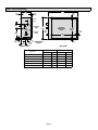
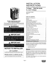
CH23 Coil Dimensions
3/4
(19)
3/4
(19)
OPENING
SAME BOTH
ENDS
SUCTION
LINE
CONDENSATE
DRAINS
AIR
FLOW
10
(254)
3/4
(19)
3/4
(19)
4
(102)
1‐1/8
(29) 2‐1/2
(64)
12
(305)
4
(102) 23
(584)
A
B
21‐1/2
(546)
LIQUID
LINE
FRONT VIEW END VIEW
3/4
(19)
3‐1/2
(89)
2‐1/4
(57)
3
(76)
Model No. A B
in. mm in. mm
CH23‐21 27 686 22‐3/4 578
CH23‐31 31 787 26‐3/4 679
CH23‐41 31 787 26‐3/4 679
CH23‐51 35 889 30‐3/4 781
CH23‐65 41 1041 36‐3/4 933
CH23‐68 47 1194 42‐3/4 1086

Page 3
Installation
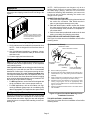
NOTE - To remove the coil from its casing after installation,
remove the two shipping screws from the coil flange. See
Figure 1.
Remove the two shipping screws
from the coil flange. The coil can't
be removed from the case if the
screws are present
Figure 1. Removing Shipping Screws
1. CH23 cabinet must be installed for horizontal air flow.
NOTE — Coils are designed for air flow from either di
rection.
2. Use field-fabricated transitions or adaptors (recom
mended 18 inches minimum width) to connect CH23
and blower unit.
3. Connect supply and return duct work.
Refrigerant Systems
CH23 coils are factory equipped with a fitting that may in
corporate either an RFCIV (fixed orifice) or TXV expansion
valve metering device.
A 90° liquid line stub and an o-ring (provided in the bag
assembly) are used with the seal nut to accommodate
installation of either type of refrigerant metering devices.
Also shipped with the coil is a 90° suction line elbow with a
1/4 inch port to facilitate the use of an expansion valve. The
size of the suction line elbow allows the suction line piping
to be routed as desired and allows room to install the TXV
bulb close to the port before insulating.
For RFC applications, use the fixed orifice shipped with
the air conditioner unit to ensure proper match-up.
For TXV applications, refer to the outdoor unit engi
neering handbook (heat pump or air conditioning unit)
data for appropriate TXV expansion valve part number.
Refrigerant Line Connections
Liquid line connections on CH23 units are 3/8 inch sweat
connections. Suction line connections on CH23 units are
7/8 inch sweat connections. Apply line sets and refrigerant
control devices to correspond with matching remote con
densing unit.
NOTE — CH23 evaporators use nitrogen or dry air as a
holding charge. If there is no pressure when you remove
the rubber plugs (Step A), check the coil or line set for
leaks before installing. After installation, pull a vacuum on
the line set and coil before releasing the outdoor unit
charge into the system.
CONNECTING SUCTION LINE
1. Place heat shield against the piping plate and around
the suction line connection. Heat shield must be in
place to guard against damage to the paint.
2. With heat shield in place, sweat in suction line. Suction
line elbow service port has no core. Secure cap to port
to prevent leakage. After procedure is completed, re
move heat shield.
3. Refer to instructions provided with outdoor unit for leak
testing, evacuating and charging procedures.
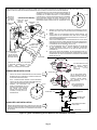
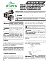
FIXED ORIFICE APPLICATIONS (LIQUID LINE)
Use Figure 2 to either remove or installation a fixed orifice
metering device.
TEFLON RING
FIXED ORIFICE
(Uncased Coil Shown)
BRASS NUT
LIQUID LINE ASSEMBLY
(INCLUDES STRAINER)
LIQUID LINE ORIFICE HOUSING
DISTRIBUTOR TUBES
DISTRIBUTOR
ASSEMBLY
REMOVE AND DISCARD
WHITE TEFLON SEAL (IF
PRESENT)
ARemove rubber plug liquid line.
BEnsure that the fixed orifice supplied with the outdoor unit is
installed with the nylon seat pointing toward the distributor
assembly.
CApply a small amount of refrigerant oil on the Teflon ring and
insert the Teflon ring securely into the orifice housing.
DAttached the liquid line assembly to the liquid line orifice
housing. Finger tighten and use an appropriately sized
wrench to turn an additional 1/2 turn clockwise as illustrated in
Figure 3, or 20 ft-lb.
EPlace the supplied fixed orifice sticker on the indoor cabinet
after installation.
Figure 2. Typical Fixed Orifice Metering Device
Installation Procedure
TXV APPLICATIONS (LIQUID LINE)
Use Figure 2 to either remove or installation a fixed orifice
metering device.

Page 4
AATTACH THE VAPOR LINE SENSING BULB IN THE PROPER
ORIENTATION AS ILLUSTRATED TO THE RIGHT USING THE
CLAMP AND SCREWS PROVIDED.
NOTE - CONFIRM PROPER THERMAL CONTACT BETWEEN
VAPOR LINE AND CHECK EXPANSION BULB BEFORE INSU
LATING THE SENSING BULB ONCE INSTALLED.
BCONNECT THE EQUALIZER LINE
FROM THE EXPANSION VALVE TO
THE EQUALIZER VAPOR PORT ON
THE VAPOR LINE. FINGER
TIGHTEN THE FLARE NUT PLUS
1/8 TURN (7 FT-LBS) AS ILLUS
TRATED BELOW.
THE EXPANSION VALVE UNIT CAN BE INSTALLED INTERNAL OR
EXTERNAL TO THE INDOOR COIL. IN APPLICATIONS WHERE AN
UNCASED COIL IS BEING INSTALLED IN A FIELD-PROVIDED
PLENUM, INSTALL THE CHECK EXPANSION VALVE IN A MANNER
WHICH PROVIDES ACCESS FOR FIELD SERVICING OF THE
EXPANSION VALVE. REFER TO BELOW ILLUSTRATION FOR
REFERENCE DURING INSTALLATION OF EXPANSION VALVE
UNIT.
TWO PIECE
PATCH PLATE
(UNCASED
COIL ONLY)
VAPOR
LINE
LIQUID LINE
ORIFICE
HOUSING
DISTRIBUTOR
TUBES
LIQUID LINE
MALE EQUALIZER LINE
FITTING (SEE
EQUALIZER LINE
INSTALLATION FOR
FURTHER DETAILS)
SENSING
LINE
EQUALIZER
LINE
EXPANSION
VALVE
TEFLON®
RING
(Uncased Coil Shown)
SENSING BULB INSULATION IS REQUIRED
IF MOUNTED EXTERNAL TO THE COIL
CASING. SEE SENSING BULB
INSTALLATION FOR BULB POSITIONING.
STUB
END
TEFLON®
RING
LIQUID LINE
ASSEMBLY WITH
BRASS NUT
DISTRIBUTOR
ASSEMBLY
THIS OUTDOOR UNIT IS DESIGNED FOR USE IN SYSTEMS THAT USE A CHECK EXPANSION VALVE METERING DEVICE. SEE THE OUTDOOR UNIT
PRODUCT SPECIFICATION FOR APPROVED EXPANSION VALVE KIT MATCH-UPS AND APPLICATION INFORMATION.
AREMOVE THE FIELD-PROVIDED FITTING THAT TEMPORARILY RECON
NECTED THE LIQUID LINE TO THE INDOOR UNIT'S DISTRIBUTOR AS
SEMBLY.
BINSTALL ONE OF THE PROVIDED TEFLON® RINGS AROUND THE
STUBBED END OF THE EXPANSION VALVE AND LIGHTLY LUBRICATE
THE CONNECTOR THREADS AND EXPOSE SURFACE OF THE TEFLON®
RING WITH REFRIGERANT OIL.
CATTACH THE STUBBED END OF THE EXPANSION VALVE TO THE LIQUID
LINE ORIFICE HOUSING. FINGER TIGHTEN AND USE AN APPROPRIATELY
SIZED WRENCH TO TURN AN ADDITIONAL 1/2 TURN CLOCKWISE AS IL
LUSTRATED IN THE FIGURE ABOVE, OR 20 FT-LB.
DPLACE THE REMAINING TEFLON® WASHER AROUND THE OTHER END
OF THE EXPANSION VALVE. LIGHTLY LUBRICATE CONNECTOR
THREADS AND EXPOSE SURFACE OF THE TEFLON® RING WITH RE
FRIGERANT OIL.
EATTACH THE LIQUID LINE ASSEMBLY TO THE EXPANSION VALVE. FIN
GER TIGHTEN AND USE AN APPROPRIATELY SIZED WRENCH TO TURN
AN ADDITIONAL 1/2 TURN CLOCKWISE AS ILLUSTRATED IN THE FIGURE
ABOVE OR 20 FT-LB.
VAPOR LINE
FLARE NUT
COPPER FLARE
SEAL BONNET
MALE BRASS EQUALIZER
LINE FITTING
FLARE SEAL CAP
OR
12
3
4
5
6
7
8
9
10
11 12 1/2 TURN
SENSING BULB INSTALLATION
EQUALIZER LINE INSTALLATION
REMOVE AND DISCARD EITHER THE FLARE SEAL CAP OR FLARE
NUT WITH COPPER FLARE SEAL BONNET FROM THE EQUALIZER
LINE PORT ON THE VAPOR LINE AS ILLUSTRATED IN THE FIGURE
TO THE RIGHT.
ON 7/8” AND LARGER LINES,
MOUNT SENSING BULB AT
EITHER THE 4 OR 8 O'CLOCK
POSITION. NEVER MOUNT
THE SENSING BULB ON
BOTTOM OF LINE.
12
ON LINES SMALLER THAN
7/8”, MOUNT SENSING
BULB BETWEEN THE 9
AND 3 O'CLOCK
POSITIONS.
12
BULB
VAPOR LINE
NOTE - NEVER MOUNT
THE SENSING BULB ON
BOTTOM OF LINE.
BULB
BULB
BULB
9 O'CLOCK TO
3 O'CLOCK
1
2
3
4
5
6
7
8
9
10
11 12
1/8 TURN
Figure 3. Typical TXV Metering Device Removal and Installation Procedure

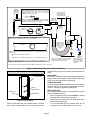
Page 5
ABOVE
FINISHED
SPACE?
OVERFLOW DRAIN LINE
ALWAYS RUN AN OVERFLOW DRAIN LINE. IF NOT POSSIBLE TO
ROUTE OVERFLOW DRAIN LINE, INSTALL LOW VOLTAGE
OVERFLOW SWITCH KIT. WIRE KIT TO SHUT DOWN
COMPRESSOR PER INSTRUCTIONS.
NO
YES
OEM CATALOG#
X3169 CLEAN OUT
VENT
PRESS IN
(DO NOT GLUE)
VENT MUST EXTEND
ABOVE HEIGHT OF
COIL DRAIN PAN BY
TWO INCHES (51MM)
1” X 3/4” X 3/4”
REDUCING
TEE WITH
PLUG
OEM CATALOG
NUMBERS* P-TRAP
49P66, J-TRAP #
91P90 OR ANY PVC
SCH 40 P- OR
J-TRAP 3/4”
OVERFLOW
DRAIN
OPTIONAL
SAFETY
PAN
COIL DRAIN PAN
WHEN A COIL IS LOCATED ABOVE A FINISHED SPACE, A 3/4” (19.1MM) SECONDARY DRAIN
LINE MUST BE:
CONNECTED TO SECONDARY DRAIN PAN
OR
CONNECTED TO THE OVERFLOW DRAIN OUTLET OF THE AIR HANDLER DRAIN PAN.
TRAPS MUST BE DEEP ENOUGH TO OFFSET MAXIMUM STATIC DIFFERENCES —
GENERALLY, TWO INCHES (51MM).
DRAIN LINE SHOULD
SLOPE A MINIMUM OF
ONE INCH PER 10
FEET (25MM PER 3
METERS)
NOTE — WHEN A AIR HANDLER IS LOCATED ABOVE A FINISHED SPACE THE SECONDARY DRAIN
PAN MUST HAVE A LARGER FOOTPRINT THAN THE AIR HANDLER.
MAIN
DRAIN
TO APPROVED
DRAIN
FOR NEGATIVE PRESSURE COILS (BLOWER
AFTER COIL) TRAPS ARE REQUIRED ON ALL
DRAIN LINES CONNECTED TO COIL.
COMPACT OVERFLOW SWITCH WITH 3/4” FEMALE SLIP INLET
AND MALE ADAPTER, TWO PART DESIGN FOR USE WHERE
OBSTRUCTIONS PREVENT DIRECT THREADING
SECONDARY
DRAIN PAN
2”
(51MM)
TRAP DEPTH
*OEM CATALOG # P-TRAP 49P66 REQUIRES A LARGER INSTALLATION SPACE THAN THE J-TRAP 91P90.
Figure 4. Typical Main and Overflow Drain Installations
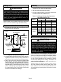
Condensate Drain Connections
MAIN DRAIN
OVERFLOW
DRAIN
SUCTION
CONNECTION
LIQUID
CONNECTION
Figure 5. Connections
CH23 coil has both main and overflow drains. Overflow
drain removes condensation should main drain become
plugged. Refer to Figure 5 for auxiliary and main drain loca
tions.
MAIN DRAIN
Connect the main drain and route downward to drain line or
sump. Do not connect drain to a closed waste system. See
Figure 4 for typical drain trap configuration.
OVERFLOW DRAIN
It is recommended that the overflow drain is connected to a
overflow drain line for all units. If overflow drain is not con
nected, it must be plugged with provided cap.
BEST PRACTICES
The following best practices are recommended to ensure
better condensate removal:
Main and overflow drain lines should NOT be smaller
than both drain connections at drain pan.
Overflow drain line should run to an area where home
owner will notice drainage.
It is recommended that the overflow drain line be
vented and a trap installed. Refer to local codes.

Page 6
Sealing Ducts
WARNING
There must be an airtight seal between the bottom of the
furnace and the return air plenum. Use fiberglass sealing
strips, caulking, or equivalent sealing method between
the plenum and the air handler cabinet to ensure a tight
seal. Return air must not be drawn from a room where
this air handler or any gas-fueled appliance (i.e., water
heater), or carbon monoxide-producing device (i.e.,
wood fireplace) is installed.
Ensure the duct is secured and all joints are properly
sealed to either the coil cabinet flanges (fully cased mod
els) or the furnace cabinet flanges (uncased models).
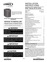
Evaporator Coil Air Pressure Drop
1. Drill test holes in supply duct to read pressure drop
across CH23 coil. See Figure 6.
CENTER PLUMBING
CONNECTIONS
HORIZONTALLY
IN DUCT
6 in
(152 mm)
AIR TEST HOLES
BLOWER
UNIT
TRANSITION
DUCT SUPPLY
DUCT
MANOMETER
ZERO END
Figure 6. Air Test Hole Locations
2. Connect draft gauge with zero end of scale at air enter
ing side of coil. Insert 1/4 inch (6 mm) of test holes in
side cabinet. Seal around test hose with permagum.
3. Table 1 lists a range of air volumes and equivalent draft
gauge readings, as well as maximum operating CFM.
Observe draft gauge readings with blower access pan
el in place and blower operating. If reading is low, close
adjustable pulley or wire direct drive blower to higher
speed. If reading is high, open adjustable pulley or wire
to a lower blower speed. Close blower access panel
each time to eliminate false readings.
Clean-Up
1. Insulate refrigerant connections at CH23 coil system
suction line. Use a wrap-around insulation.
2. Set room thermostat at desired setting.
3. Pick up all shipping cartons, metal scraps, extra insula
tion and clean up the installation area.
Table 1. Draft Gauge Reading (Dry Evaporator)
400 CFM/190 L/S Per Ton
Model No. Air Volume Total Resistance
cfm L/s in. w.g. Pa
CH23‐21
600 285 .05 12
800 380 .07 17
CH23‐31 1000 470 .04 10
CH23‐41 1200 565 .09 22
CH23‐51 1600 755 .17 42
CH23‐65
CH23‐68
1800 850 .20 50
2000 945 .24 60
2200 1040 .28 70
2400 1135 .32 80
Maintenance
CAUTION
A damaged coil fin can affect equipment operation and
performance. Do not use flame, high-pressure water,
steam, or volatile cleaners on fins or tubing surfaces. If
cleaning requires the use of acidic or alkaline cleaners,
follow the manufacturer's instructions. Thoroughly flush
cleaner from all equipment components. (Be careful to
prevent damage or corrosion of the components
connected to the system or areas surrounding the
equipment being cleaned.)
A trained technician or service agency must perform main
tenance and service on equipment. At the beginning of
each ing or cooling season, indoor coils should be cleaned.
Do not use hydrofluoric acid, alkaline, or similar chemicals
on coils. These chemicals are not necessary to dissolve
salt, and may damage the fin coating. Acid washes are
used to dissolve oils and greases, which generally are not
present on most installations.
Alkaline washes are useful for dissolving oxides such as
zinc oxide, aluminum oxide, and iron oxide (rust). These
three oxides are more corrosion‐resistant than base met
als, so dissolving or removing them will cause an increase
in corrosion.

Page 7
CLEANING THE COIL:
1. Remove the coil from the cabinet or plenum, and take
the coil to an appropriate place to clean it.
2. Vacuum or brush the coil to remove matted and sur
face debris from the fin. Use vacuum attachments and
/or brushes that are non-destructive to fins.
3. If oil deposits are present, spray the coil with ordinary
household liquid detergent. Allow detergent to soften
deposits and wait 10 minutes.
NOTE - For units in coastal regions, fresh water will dis
solve away any salt deposits. (Wash coils with fresh water
at least every six months.)
4. Spray the coil at a vertical angle of 30 to 45 degrees
with a constant stream of water at moderate pressure.
A pressure washer with a fan nozzle will work best. Do
not spray the coil from a horizontal direction.
5. Direct the spray so that any debris is washed out of the
coil and basepan. For most residential units, hot water
is not necessary.
NOTE - Attempting to back flush from the inside of the coil
will require removing parts from the unit, and it may be very
difficult to flush the whole coil surface. Attempting to blow
water through a coil will slow the water stream and reduce
the flushing action of the outer fin surface.
6. Replace the coil into the cabinet or plenum. Ensure
that you have followed the proper procedure for routing
and securing the refrigerant tubing.
Do not use hydrofluoric acid, alkaline, or similar chemicals
on coils. These chemicals are not necessary to dissolve
salt, and may damage the fin coating. Acid washes are
used to dissolve oils and greases, which generally are not
present on most installations.
Alkaline washes are useful for dissolving oxides such as
zinc oxide, aluminum oxide, and iron oxide (rust). These
three oxides are more corrosion‐resistant than base met
als, so dissolving or removing them will cause an increase
in corrosion.
-
 1
1
-
 2
2
-
 3
3
-
 4
4
-
 5
5
-
 6
6
-
 7
7


Lennox CH23 Series Coils Installation guide
- Type
- Installation guide
Ask a question and I''ll find the answer in the document
Finding information in a document is now easier with AI
Related papers
-
Lennox Heat Pump 50677201 User manual
-
-
-
Lennox Heat Pump 506586-01 User manual
-
-
-
-
-
Lennox Merit 14HPX-060 Installation Instructions Manual
-
 Lenox Elite XP16-024-230 User manual

Other documents
-
Carrier CNRVU1814ALA Installation Instructions Manual
-
 Blueridge BH1P36B Installation guide
-
Allied 4SCU23LX User manual
-
COMFORT-AIRE MCG60P21E Installation, Operation & Maintenance Manual
-
Allied Commercial 14V87A Operating instructions
-
Rheem RCF3621SEAMCA Installation guide
-
Allied 4AC16L Installation guide
-
 Allied Commercial 14V87A Installation, Operation & Maintenance Manual
-
Aspen Manufacturing CE48D44175L015 Installation guide
-
 Aspen Manufacturing CE48C44210L087 Installation guide


