Page is loading ...

Model 400
B/W Reflection
Densitometer
Operation Manual

ii
Dear Customer:
Congratulations! We at X-Rite, Incorporated are proud to present
you with the X-Rite 400 B/W Reflection Densitometer. This
instrument represents the very latest in microcontrollers, integrated
circuits, optics, and display technology. Your X-Rite 400 is a
rugged, reliable, finely engineered instrument whose performance is
unsurpassed.
To fully appreciate and protect your investment, we suggest that you
take the necessary time to read and fully understand this manual. As
always, X-Rite stands behind your 400 with a full one year limited
warranty and a dedicated service organization. If the need arises,
please don’t hesitate to call us.
Thank you for your trust and confidence.
X-Rite, Incorporated

iiii
CE DECLARATION
Manufacturer's Name: X-Rite, Incorporated
Manufacturer's Address: 3100 44
th
Street, S.W.
Grandville, Michigan 49418
U.S.A.
Model Name: Densitometer
Model No.: 400
Directive(s) Conformance: EMC 89/336/EEC LVD 73/23/EEC
NOTE: The device complies to the product specifications for the Low Voltage
Directive when furnished with the 230VAC AC Adapter (X-Rite P/N SE30-62),
and to UL Standards when furnished with the 115VAC AC Adapter
(X-Rite P/N SE30-61).

iiiiii
FEDERAL COMMUNICATIONS COMMISSION NOTICE
FCC Statement
This equipment has been tested and found to comply with the limits
for a Class A digital device, pursuant to Part 15 of the FCC Rules.
These limits are designed to provide reasonable protection against
harmful interference when the equipment is operated in a
commercial environment. This equipment generates, uses, and can
radiate radio frequency energy and, if not installed and used in
accordance with the instruction manual, may cause harmful
interference to radio communications. Operation of this equipment
in a residential area is likely to cause harmful interference in which
case the user will be required to correct the interference at his own
expense.
Canada
This Class A digital apparatus meets all requirements of the
Canadian Interference-Causing Equipment Regulations.
Cet appareil numérique de la classe A respecte toutes les exigences
du Règlement sur le matériel brouilleur du Canada.
The Manufacturer: X-Rite, Incorporated
Der Hersteller: 3100 44th Street, S.W.
El fabricante: Grandville, Michigan 49418
Le fabricant:
Il fabbricante:
Declares that: Densitometer
gibt bekannt: 400
advierte que:
avertit que:
avverte che:
is not intended to be connected to a public telecommunications network.
an ein öffentliches Telekommunikations-Netzwerk nicht angeschlossen werden soll.
no debe ser conectado a redes de telecomunicaciones públicas.
ne doit pas être relié à un réseau de télécommunications publique.
non deve essere connettuto a reti di telecomunicazioni pubblici.

iviv
CAUTION: Operational hazard exists if AC adaptor other than
X-Rite SE30-61 (115V) or SE30-62 (230V) is used.
VORSICHT: Betriebsgefahr besteht bei Gebrauch von anderen
Adaptern als X-Rite SE30-61 (115 U) oder SE30-62 (230 U).
AVISO: No use otro adaptador C.A. que no sea la pieza X-Rite
SE30-61 (115V) o SE30-62 (230V), por el riesgo de mal
funcionamiento del equipo.
ATTENTION: Ne pas utiliser d’adaptateur autre que SE30-61
(115V) ou SE30-62 (230V) de X-Rite au risque de mauvais
fonctionnement de l’appareil.
AVVISO: Non usare un altro adattatore C.A. che non è del pezzo
X-Rite SE30-61 (115V) o SE30-62 (230V), per il rischio di
malfunzionamento dell’apparecchio.
NOTE: Shielded interface cables must be used in order to
maintain compliance with the desired FCC and European emission
requirements.

vivi
Contents
1 Overview and Setup
Features............................................................................ 1-1
Packaging and Parts............................................................ 1-3
Instrument Vocabulary ......................................................1-4
Unlocking/Locking the Shoe.............................................. 1-5
Batteries and Power.......................................................... 1-6
Adjusting the Display Angle............................................... 1-9
I/O Port Setup...................................................................1-10
2 Calibration
Response Settings ............................................................ 2-1
Overview of Calibration Procedures.................................. 2-2
Long Calibration................................................................ 2-3
Quick-Cal™ ......................................................................2-4
3 Density Functions
Selecting Density Function................................................ 3-2
Density Measurement........................................................ 3-2
Density Difference Measurement ......................................3-3
Miscellaneous Display Messages ......................................3-4
4 Dot Functions
Dot Formula......................................................................4-1
Selecting Dot Area or Dot Gain ......................................... 4-4
Dot Area Function............................................................. 4-5
Dot Gain Function.............................................................4-7
5 Range Functions
Reference Value ............................................................... 5-1
Absolute Range Measurement ..........................................5-2
Range Minus Reference Measurement.............................. 5-2
6 Technical Information
Serial Interface Information...............................................6-1
Instrument Specifications.................................................. 6-4
Accessories....................................................................... 6-6
General Cleaning.............................................................. 6-7
Optics Maintenance........................................................... 6-7
Target Window Replacement............................................ 6-8
Lamp Replacement........................................................... 6-9

viivii
7 Appendices and Index
Proprietary Notice ............................................................. 7-1
Limited Warranty............................................................... 7-2
Index................................................................................. 7-3
Copyright 1998 by
X-Rite, Incorporated
“ALL RIGHTS RESERVED”
X-Rite is a registered trademark and Quick Cal™, Q Cal™, Electronic Function
Selection™, Computerized Color Response™, and CCR™, are trademarks of X-Rite,
Incorporated. All other logos, brand names, and product names are the properties of their
respective holders.

1-11-1
1 Overview
and Setup
Features................................... 1-1
Packaging and Parts.................... 1-3
Instrument Vocabulary.............. 1-4
Unlocking/Locking the Shoe...... 1-5
Batteries and Power.................. 1-6
Adjusting the Display Angle ...... 1-9
I/O Port Setup..........................1-10
The X-Rite 400 B/W Reflection Densitometer is designed to meet
the quality control needs of the general graphic arts,
phototypesetting, and newspaper industries. This completely
portable instrument features different measurement modes for
quickly measuring ink density, density difference, dot area, and dot
gain. Measurements are taken with simple hand-held operation, and
measurement data is clearly read on the interactive display. The
three control buttons make measurement mode selection easy.
FEATURES
The X-Rite 400 features several state-of-the-art technologies that
place the instrument a step above competitive instruments in terms
of accuracy, speed, and simplicity:
QuickCal™ One-Step Calibration
The 400’s Quick-Cal feature makes calibration fast and easy. You
simply select the “Q-Cal” mode on the instrument, then measure the
white patch on the supplied calibration target card. You can also get
complete agreement with other densitometers using the three-color
response calibration.
DEN (Density)
The DEN function allows you to take absolute density and density
difference measurements.

400 B/W Reflection Densitometer
1-21-2
DOT
The DOT function allows Dot area and Dot gain measurements. Dot
is calculated with paper subtracted out using the Murray-Davies or
Yule-Nielson formulas.
Range
Range subtracts the lowest measurement from the highest and
displays the difference. Range-Reference subtracts a reference value
from the range and displays the difference.
Nonvolatile Memory
A lithium battery stores calibration data and measured values when
the densitometer’s primary rechargeable batteries are depleted or
removed.
Additional Features
Ÿ Large LCD display clearly identifies measurement data and
mode function. No need for numeric codes to identify this
information.
Ÿ Three large buttons place all function controls at operator’s
fingertips.
Ÿ AC adapter is provided to allow readings while batteries are
being recharged.
Ÿ Two-way RS-232 interface operates at 1200 baud, or one of
several other baud rates.

Overview and Setup
1-31-3
PACKAGING AND PARTS
After removing the instrument from the shipping carton, inspect for
possible damage. If any damage is noted, contact the transportation
company immediately. Do nothing more until the carrier’s agent has
inspected the damage.
If damage is not evident, check to ensure that all items are included
(refer to the parts list below).
Your Package Should Include…
1 400 B/W Reflection Densitometer
1 Carrying Case
1 Operation Manual
1 Reflection Calibration Reference 400-62
1 Warranty Registration Card
1 P/N SE30-61 Battery Charger, 115V
or P/N SE30-62 Battery Charger, 230V
1 P/N SD01-41 Certificate of Calibration
Along with this Operation Manual, several important notices are
included. You should read each of these notices before using the
instrument.
Return Packaging
Your X-Rite 400 was packaged in a carton specially designed to
prevent damage. If re-shipment is necessary, the instrument should
be re-packaged in the original carton. If the original carton is not
available, a new one can be obtained from X-Rite.

400 B/W Reflection Densitometer
1-41-4
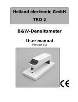
INSTRUMENT VOCABULARY
FUNCTION
ENTER ZERO
8-character
Interactive Display
3 Operating Keys
AC Adapter
(Charger) Jack
RS232
I/O Port
Target Window
Shoe
FUNCTION
Button
ENTER Button
ZERO
Button
Arrows indicate button’s function for
adjusting display values up or down.

Overview and Setup
1-51-5
UNLOCKING/LOCKING THE SHOE
To take measurements with the instrument, you must unlock the
Shoe (see Instrument Vocabulary drawing in previous chapter).
When the instrument is not in use, the Shoe should be re-locked to
protect the instrument optics.
A sliding button on the bottom of the instrument locks the Shoe
closed.
To unlock, hold Shoe against the unit and slide the lock button back
until the button latch clears the Shoe tab. Carefully release the Shoe
to open. (Figure 1-1)
To lock, hold the Shoe against the unit and slide the lock button
forward until the button latch captures the Shoe tab. (Figure 1-2)
Figure 1-1 Figure 1-2
Button Latch
Shoe Tab
Latch
captures Tab

400 B/W Reflection Densitometer
1-61-6
BATTERIES AND POWER
Your 400 instrument’s batteries should be charged before use. It can
be operated while the batteries are being charged.
Before you begin charging, you must remove the battery isolation
insert protruding from the battery cover. (Figure 1-3)
Figure 1-3
NOTE: Make sure the voltage indicated on the AC adapter complies
with the AC line voltage in your area. If it does not, contact your
X-Rite dealer.
To charge the battery:
1. Plug the AC Adapter Line Cord into the AC Adapter Jack on
back of instrument. (Figure 1-4)
2. Plug AC Adapter into AC wall outlet.
You can use the instrument while it recharges. The instrument
will be fully charged in approximately 14 hours.
Figure 1-4
Battery Isolation Tab
Plug AC Adapter Cord
into AC
Adapter Jack

Overview and Setup
1-71-7
NOTE: If your unit has not been used for several weeks recharge for
approximately 24 hours.
NOTE: When storing the unit for a long period of time, the
batteries should be removed.
Applying Power
The instrument remains “powered down” until a measurement is
taken. When a measurement is taken, or when any key is pressed,
the instrument automatically turns on.
If no measurements are taken or keys pressed for 45 seconds, the
instrument automatically turns off again to conserve battery power.
Inserting/Removing the Batteries
Your instrument is shipped with six AA NI-CAD batteries already
installed. Should you ever need to replace the batteries, first close
and lock the Shoe (when the shoe is unlocked and open, it blocks
the battery door). Next, slide the battery door in the rear of the
instrument down and off. The batteries will spring out a bit.
To replace the batteries, insert six fresh AA NI-CAD batteries into
the instrument, three into each chamber. Note the proper polarity
of the batteries in Figure 1-5, and on the CAUTION label
beneath the instrument. You will need to press and hold the
batteries down in place while you slide the battery cover back on.
Push the cover into place until it is flush with the bottom of the
instrument.

400 B/W Reflection Densitometer
1-81-8
Figure 1-5

Overview and Setup
1-91-9
ADJUSTING THE DISPLAY ANGLE
You can most clearly read the LCD display by viewing it at a 90º
angle. The angle of the display can be adjusted to accommodate this
for different user sight lines.
To adjust the display angle:
1. Set the Display Angle Adjustment Knob on the right side of the
instrument to its midpoint setting. (Figure 1-6)
Figure 1-6
2. Activate the display by taking a measurement or pressing a
control button.
3. Adjust the Display Angle Adjustment Knob until the displayed
data can be most clearly seen from your line of sight.
Display Angle
Adjustment Knob

400 B/W Reflection Densitometer
1-101-10
I/O PORT SETUP
Your X-Rite 400 has a serial port that allows data to be transmitted
toor received from an external device. With this I/O connection
made, the 400 can controlled externally by Serial Input Commands.
If you do not plan to use the I/O port at this time, you can skip
ahead to Chapter 2, “Calibration.”
You can configure different functions of your I/O port using the
instrument’s MODE selection procedures. You can set up:
Ÿ The desired Baud rate (output rate of characters per second) for
transmitting data via the I/O port;
Ÿ the desired header (HDR) that will appear above the transmitted
or printed data; and
Ÿ the desired computer output format (COMP).
To set up the I/O port:
1. Press the FUNCTION button and the ENTER button
simultaneously, then release.
N cal X Y appears in the display, where “X” represents the
installed response (B or R).
2. Press FUNCTION to indicate no, you do not want to calibrate.
N mode Y appears in the display.
3. Press ZERO to indicate yes, you do want to set mode. ↓ I/O Y
appears in the display.
4. Press ZERO to indicate yes, you do want to set I/O Ports. Each
depression of ZERO will alternate between Aenter and Menter
When Aenter is selected, data is automatically transmitted at
the end of each measurement.
When Menter is selected, data is manually transmitted after
a measurement by pressing SEND.
N calX Y
N mode Y
^ Aenter
^ I/O Y

Overview and Setup
1-111-11
5. Press FUNCTION to advance to HDR. Each depression of
ZERO will alternate between HDR ON and HDR OFF.
When HDR ON is selected, a header will appear above
transmitted or printed data indicating the data typeeither
DEN (density) or DOT.
—When HDR OFF is selected, no header appears.
6. Press FUNCTION to advance to COMP. Each depression of
ZERO will alternate between COMP ON and COMP OFF.
When COMP ON is selected, transmitted or printed data will
simply be configured with single spaces between each
measurement value.
When COMP OFF is selected, transmitted or printed data
will be configured in a “column” format, with a carriage return
and line feed after each measurement value.
7. Press FUNCTION three times to exit to normal operation.
HDR ON
COMP ON
DEN
C 1.24
C 1.24
DEN V0.67 C0.20 M1.23 Y0.77
DEN
V0.67
C0.20
M1.23
Y0.77

400 B/W Reflection Densitometer
1-121-12
RS232 Connector Interface
Your X-Rite 400 instrument can be connected to a computer or
printer using a standard RS232 9-pin connector.
For more information on Serial Input Commands and remote
control operation of the 400 contact X-Rite Technical Services.
I/O Port for Serial Interface

2-12-1
2 Calibration
Response Settings.................... 2-1
Overview of Calibration
Procedures............................... 2-2
Long Calibration ....................... 2-3
Quick-Cal™..............................2-4
Frequency of Calibration
Under long operating conditions, the instrument should be calibrated
once per week, or whenever the instrument displays a message
regarding calibration. You should perform a “long calibration”
whenever possible. However, you can also perform a Quick-Cal™
procedure any time after an initial long calibration has been performed.
Before calibrating, you should determine the appropriate densitometer
response setting for your instrument, based on your production control
requirements.
RESPONSE SETTINGS
A densitometer’s measurement system consists of several different
components (lamp, optics, light sensor). Different densitometers consist
of different types of these components. The density readings measured
by these systems are called a densitometer response. Because
components differ among densitometers, standard responses have been
established in the industry. These standards ensure that even
instruments with different components will measure in accordance with
the same response.
/