
Read these instructions completely before beginning
installation. Failure to follow them could cause a heater
malfunction resulting in serious injury and/or property
damage.
WARNING: All electric heaters have hot and arcing or
sparking parts inside. Do not use it in areas where gaso-
line, paint or ammable liquids are or are stored.
WARNING: This heater is tested and listed for use only
with the optional accessories listed in these instruc-
tions. Use of optional accessories not specically
tested for this heater could void the heater warranty
and/or result in a safety hazard.
This replace meets the construction and safety stan-
dards of H.U.D. for application in manufactured homes
when installed according to these instructions.
INSTALLER: Leave this manual with the appliance.
CONSUMER: Retain this manual for future reference.
For more information, visit www.desatech.com
ELECTRIC FIREPLACE/INSERT
SAFETY INFORMATION AND INSTALLATION MANUAL
FOR MODELS CGEF26A, VEF26A and ES300

www.desatech.com
119624-01A2
SAFETY INFORMATION
WARNING: Improper installa-
tion, adjustment, alteration, ser-
vice or maintenance can cause
injury or property damage. Refer
to this manual. For assistance or
additional information, consult
a qualied installer.
CAUTION: Do not expose the
heater to the elements (such as
rain, etc).
CAUTION: The replace insert
unit is mounted on rubber feet. The
purpose is to ensure adequate air
circulation beneath unit. DO NOT
remove these feet. Do not install
directly on carpet, rug, furniture
or similar surfaces which could
hinder or block the air ow.
Due to high temperatures, the
rebox should be located out of
trafc and away from furniture
and draperies.
Do not place clothing or other
ammable material on or near
rebox. Never place any objects
on the replace.
Carefully supervise young chil-
dren when they are in the room
with replace.
Fireplace becomes very hot
when running. Keep children and
adults away from hot surfaces to
avoid burns or clothing ignition.
Fireplace will remain hot for a
time after shutdown. Allow sur-
faces to cool before touching.
When using electrical heaters, basic precautions
should always be followed to reduce the risk of
re, electric shock and injury to persons, including
the following:
1. Read all instructions before using this heater.
2. Keep combustible materials, such as furniture,
pillows, bedding, papers, clothes and curtains
at least 3 feet from front of heater and keep
them away from sides and rear.
3. Always unplug heater when not in use.
4. Do not operate any heater with a damaged cord
or plug or after heater malfunctions, has been
dropped or damaged in any way. Return heater
to authorized service facility for examination,
electrical or mechanical adjustment or repair.
5. Do not use outdoors.
6. This heater is not intended for use in bath-
rooms, laundry areas and similar indoor
locations. Never locate heater where it may
fall into a bathtub or other water container.
7. Do not run cord under carpeting. Do not cover
cord with throw rugs, runners or the like. Ar-
range cord away from trafc area and where
it will not be tripped over.
8. To disconnect heater, turn controls to "OFF"
before removing plug from outlet.
9. Do not insert or allow foreign objects to enter any
ventilation or exhaust opening as this may cause
an electric shock or re or damage the heater.
10. To prevent possible fire, do not block air
intakes in any manner.
11. A heater has hot and arcing or sparking parts
inside. Do not use it in areas where gasoline,
paint or ammable liquids or vapors are used
or stored.
TABLE OF CONTENTS
Safety Information ............................................... 2
Listing Approvals ................................................. 3
Product Dimension Specications ....................... 3
Product Identication ........................................... 3
Locating Fireplace ............................................... 4
Unpacking and Testing Fireplace ........................ 4
Installation ........................................................... 5
Finishing .............................................................. 7
Operating Instructions ......................................... 7
Cleaning and Maintenance .................................. 8
Technical Service............................................... 10
Replacement Parts ............................................ 10
Troubleshooting ..................................................11
Illustrated Parts Breakdown and Parts List........ 12
Warranty Information ...........................Back Cover

www.desatech.com
119624-01A 3
SAFETY INFORMATION
Continued
12. Use this heater only as described in this
manual. Any other use not recommended
by the manufacturer may cause re, electric
shock or injury to persons.
13. Avoid the use of an extension cord because
the extension cord may overheat and cause
a risk of re. However, if you have to use an
extension cord, the cord should be No. 14
AWG minimum size and rated not less than
1875 WATTS.
14. Always use properly grounded fused and
polarized outlets.
15. Always use ground fault protection where
required by electrical codes.
16. Always disconnect power before performing
any cleaning, maintenance or relocation of
heater.
17. To prevent a possible re, do not burn wood
or other materials in this heater.
18. To prevent electric shock or re, always use
a certied electrician should new circuits or
outlets be required.
19. When transporting or storing heater, keep in
a dry place free from excessive vibration and
store as to avoid damage.
LISTING APPROVALS
This heater has been tested in accordance with the
CSA Standards for xed and location-dedicated
electric room heaters in the United States. All
components are UL or CSA safety certied.
If you need assistance during installation, please con-
tact your local dealer or the DESA Heating Products
Technical Services Department at 1-866-672-6040.
Description: 26" Fireplace/Insert
Voltage: 120
Watts: 1500
Amps: 15 Amp
Grounded Circuit
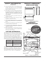
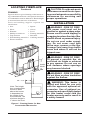
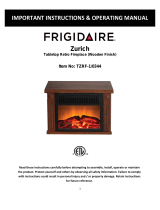
PRODUCT DIMENSION
SPECIFICATIONS
Figure 1 - Heater Dimensions
Note: This heater must be electrically wired and
grounded in accordance with local codes or, in
the absence of local codes, with National Electric
Code ANSI/NFPA 70-latest edition or the Cana-
dian Electric Code, CSA C2.1 as appropriate.
FL
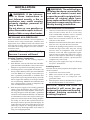
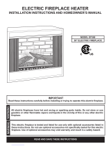
Figure 2 - Product Identication
PRODUCT
IDENTIFICATION
Top Screen
Screws
Bottom Screen
Screw
Heat Vents
Back
Glass
ON/OFF
Power Button
Flame Control
and Temp.
Buttons
Bottom Panel
Fuse
22.75
26.125
21.26
21.125
13.25
12.0
4.33
22.75
26.125
21.26
21.125
13.25
12.0
4.33

www.desatech.com
119624-01A4
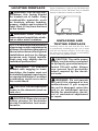
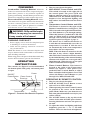
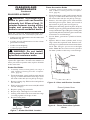
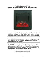
Figure 3 illustrates a variety of ways the heater may
be located in a room. The heater may be installed
directly on the oor or raised on a hearth.
LOCATING FIREPLACE
WARNING: Due to high tem-
peratures, this heater should
be located out of trafc. Keep
combustible materials such
as furniture, pillows, bedding,
papers, clothes and curtains at
least 3 feet (0.9 m) from the front
of the heater.
WARNING: Never locate this
heater where it may fall into a bath-
tub or other water container.
NOTICE: Minimum and maximum
clearances must be maintained at
all times. Illustrations throughout
these instructions reect typical
installations and are for design
purposes only. Actual installa-
tions may vary slightly due to
individual preferences.
WARNING: To prevent
contact with sagging or loose
insulation, the heater must not
be installed against vapor barrier
or exposed insulation. Localized
overheating could occur and a
re could result.
CAUTION: Do not expose the
heater to the elements (such as
rain, etc.)
CAUTION: Wear gloves and
safety glasses for protection
during installation and main-
tenance.
Figure 3 - Heater Locations
UNPACKING AND
TESTING FIREPLACE
Carefully remove the unit from the box. Prior
to permanently installing the unit, test to make
sure the unit operates properly. To do this, plug
the unit's power supply cord into a conveniently
located 120-volt grounded outlet.
CAUTION; The unit's power
supply cord must be connected
to a properly grounded and pro-
tected 120-volt outlet. Always
use ground fault protection
where required by the electri-
cal code.
WARNING: Do not operate
the unit if it is damaged or has
malfunctioned. If you suspect
the unit is damaged, return the
unit to an authorized service
facility for examination, electri-
cal or mechanical adjustment
or repair.

www.desatech.com
119624-01A 5
FRAMING
Figure 4 shows a typical framing of this heater us-
ing combustible materials. All required clearances
to combustibles must be adhered to. Header height
is measured from the base of the heater.
Tools and building supplies required for
installation:
• Saw • Square
• Pliers • Gloves
• Hammer • Level
• Phillips screwdriver • Framing materials
• Tape measure • Surround
• Wall-nishing materials • Caulking material
• Electric drill/bits
LOCATING FIREPLACE
Continued
CAUTION: Provide adequate
clearances around the air open-
ings and adequate accessibility
clearances for servicing and
proper operations.
Figure 4 - Framing Heater for New
Construction/Renovation
3/4" - 1/2"
Note: The height
that a combustible
mantel is tted
above the heater
is dependent on
the height of the
front selected. The
minimum height is
1" above the front.
26
3
/
4
"
27"
Header
Height
13"
INSTALLATION
WARNING - RISK OF FIRE!
The power cord must not be
pinched or against a sharp edge.
Secure cord to avoid tripping or
snagging to reduce the risk of re,
electric shock or personal injury.
Do not run cord under carpet-
ing. Do not cover cord with
throw rugs, runners or the like.
Arrange cord away from trafc
areas and where it will not be
tripped over.
WARNING - RISK OF FIRE!
To prevent a possible re, do
not block air intake or exhaust
in any manner. Do not use on
soft surfaces where openings
may become blocked.
WARNING - RISK OF FIRE!
Do not blow or place insulation
against the rebox.
WARNING: This heater is
tested and listed for use only
with the approved optional ac-
cessories. Use of optional ac-
cessories not specically tested
for this heater could void the
heater warranty and/or result in
a safety hazard.

www.desatech.com
119624-01A6
WARNING: If the informa-
tion in these instructions is
not followed exactly, a re or
explosion may result causing
property damage, personal in-
jury or death.
Do not store or use gasoline or
other ammable vapors in the vi-
cinity of this or any other heater.
INSTALLING AS A FIREPLACE
Select a suitable location that is not susceptible to
moisture and is away from drapes, furniture and
high trafc areas. Note: Follow all national and
local electrical codes. This insert can be installed
into either an existing replace or as new construc-
tion/renovation.
NOTICE: Never pick unit up by
louvers. Louvers will bend.
Existing Fireplace Installation
1. Thoroughly clean out the existing replace
and hearth area.
2. Seal all drafts, vents or ash clean-outs with ber-
glass insulation. Seal the ue. Once sealed, close
damper to stop debris from falling onto unit.
3. If existing re box is susceptible to moisture, cap
the top of the chimney ue to prevent inltration
of water. Note: It is strongly advised that you
hire a qualied professional to undertake this
step in order to prevent personal injury. Once the
ue is capped, the chimney is no longer suitable
for wood burning. Note: Do not install this unit
into a replace that is prone to dampness; the
area of installation must be dry.
4. Plan the power supply. If an existing grounded
outlet is near the replace, the power cord can
run along the front of the replace. If the cord is
not long enough to reach the outlet, a grounded
extension cord minimum AWG No. 14 and rated
to a minimum of 1875 watts, may be used. If you
plan to cut or drill a hole in the existing replace
for wiring, it is best to hire a professional to do
this step in order to prevent personal injury. To
reduce the risk of re, do not run the power cord
under rugs, carpets, etc. Arrange the power sup-
ply cord away from high trafc areas where it
may pose a tripping hazard.
WARNING: The solid fuel/gas
replace has been converted for
use with an electric insert and
cannot be used for original fuels
unless all original parts have
been replaced and the replace
has been reapproved by the au-
thority having jurisdiction.
New Construction or Renovation
1. Select a location that is not prone to moisture
and is located at least 0.9 m or 3 feet away
from combustible materials such as curtains
or drapes, furniture, bedding, paper, etc.
2. Place unit in selected location to see how it
will look in the future.
3. Mark the desired location on the oor and store
unit in a safe, dry and dust free location.
4. Frame in an opening leaving at least 1/4" (6 mm)
around the edge of the unit. Any new wiring
must be done in compliance with local and
national codes and other applicable regula-
tions in order to reduce the risk of re, electric
shock or other injuries. Therefore, it strongly
recommended that you hire a professional to
complete any such work.
5. Plan you power supply. See step 4 of Existing
Fireplace Installation.
Installing Insert
Once the site has been prepared, the replace insert
can be installed.
1. Install trim onto front of unit.
2. Make sure switch is in the "OFF" position.
3. Plug fireplace into a 15-amp/120 volt,
grounded outlet.
4. Push replace insert so that the trim is against
the nished mantle or wall surface.
NOTICE: When the front is
installed it will cover the gap
between the heater and framing,
cabinet, nishing materials or
existing replace.
INSTALLATION
Continued

www.desatech.com
119624-01A 7
FINISHING
Combustible Finishing Material: Materials
made of or surfaced with wood, compressed paper,
plant bers, plastics or any material capable of
igniting and burning, whether ame proofed or not,
plastered or unplastered (this includes drywall).
Noncombustible Finishing Material : Mate-
rials which will not ignite and burn. Such materials
are those consisting entirely of steel, iron, brick,
tile, concrete, slate, glass or plasters or combina-
tions thereof or have a re rating of zero.
WARNING: Grills on this heater
cannot, in any way, be covered as
it may create a re hazard.
FINISHING CHECKLIST
• Power supply service must be completed prior
to nishing to avoid reconstruction.
• Grills and air openings cannot be covered in
any circumstances.
Note: The heater is a zero clearance replace and
may be nished with combustible or noncombus-
tible nishing materials.
When using paint or lacquer to nish the mantel, they
must be heat resistant to prevent discoloration.
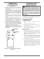
OPERATING
INSTRUCTIONS
The controls (see Figure 5) are located behind
the bottom panel. Pull gently on bottom panel
to open.
Figure 5 - Controls For Electric Fireplace
1. Pluginyourelectricreplace.
2. Main ON/OFF Power Switch and LED:
This switch is located on the right side of
the control panel. The power LED will
light up when the unit is on (see Figure 5).
When unit is on, the default settings for the
replace is low background lighting and
highemberbedandameandtheheater
is off.
3. Temperature Control Button and LED:
This button is located to the right of the
Remote Control Receiver (see Figure 5). The
LED is located to the right of the Flame But-
ton. Push button to cycle through settings.
When this button is pushed the LED will
come on. When heater is on heat will emit
through vents located in the middle of the
top louver panel (see Figure 2, page 3).
The heater has a built-in thermostat so
it will shut off automatically once the set
temperature is reached. It will also turn
on automatically if the room temperature
drops below the set temperature.
Note: When the heater is turned on for the
rsttime,itmayreleaseaslight,harmless
odor. This odor is a normal occurrence caused
by the initial heating of the internal heating
elements and should not occur again after
initial burn off. (This odor may occur again
if dust or debris has been trapped.)
4. Flame Control Button: This button is
located to the right of the Temperature
Button (see Figure 5). After power is on,
push the Flame Control Button to adjust
ameandemberbedbrightness.Pressand
release the Flame Control Button to cycle
through LO, MED, HI and OFF.
OPERATING BY REMOTE CONTROL
1. Pluginyourelectricreplace.
2. Push the ON/OFF Power Button to turn
unit on. Power LED will light.
3. When operating the remote control, it must
be pointed at the sensor on the bottom
panel. Note:Makesureyourbatteriesare
fully charged and installed correctly in your
remote control.
4. The ON/OFF button at the top left of the
remote is the main ON/OFF power button.
Pressing this button activates the power to
the unit.
5. Toadjusttheemberbedlightingandame
brightness, press the "-" or "+" FLAME
buttons . There are four levels of brightness.
FL
ON/OFF
Power Button
Receiver
Flame Control
Power
Heater
Temperature

www.desatech.com
119624-01A8
OPERATING
INSTRUCTIONS
Continued
CLEANING AND
MAINTENANCE
WARNING: Always discon-
nect power and allow the heater
to cool before performing any
cleaning, maintenance or reloca-
tion of this heater. Turn controls
to OFF and remove plug from
outlet or turn off circuit breaker
to heater.
Turn off heater and circuit breaker to heater before
performing any cleaning and/or maintenance. Al-
low heater to cool completely.
CLEANING FIREBOX
COMPARTMENT
1. Remove screws that hold front panel in
place.
2. Carefully remove front panel.
3. Using the brush vacuum attachment, gently
clean compartment.
4. After cleaning compartment, replace front
panel. Reset circuit breaker.
BACK GLASS
1. The glass is cleaned in the factory during
assembly. During shipment, installation, han-
dling, etc. the glass surface may collect dust
particles. These can be removed by bufng
lightly with a clean dry cloth.
2. To remove ngerprints or other marks, the
glass can be cleaned with a damp cloth using
a good quality household glass cleaner. The
glass should be completely dried with a lint
free cloth or paper towel.
3. In the event of glass breakage, vacuum all
remaining glass pieces with a shop vac. DO
NOT VACUUM WHILE PIECES ARE HOT.
Replace glass only with replacement part
specically for this heater. Never substitute
material. Only fully tempered soda lime safety
glass may be used on this heater.
6. The HEATER button activates the heater,
The heater is pre-set to the following
temperatures:
HI will shut off when room reaches approxi-
mately 86° F (30° C). The LED will be red.
MED will shut off when room reaches ap-
proximately 75° F (24° C). The LED will be
orange.
LO will shut off when room reaches ap-
proximately 64°F (18° C). The LED will be
green.
7. To adjust the light that shines on the logs
use the LAMP button. To increase or de-
crease, press the "-" or "+" buttons to cycle
through the four brightness settings.
8. Toturnoffthereplace,presstheON/OFF
buttononce.Whenyourestartthereplace
with the remote control, all of the features
you had set will remain in effect.
NOTICE: This remote control must remain
within8metersor26feetofthereplaceto
be effective.
FLAME
ON/OFF
+-
+-
HEATER
LAMP
Indicator
Light
Infrared
Ray Exit
Figure 6 - Remote Control For Electric
Fireplace

www.desatech.com
119624-01A 9
BULB REPLACEMENT
WARNING: The halogen light
bulbs in your unit can become
extremely hot. Allow at least 10
minutes between turning off the
heater and removing the light
bulbs to avoid accidental burns.
There are a total of 8 halogen light bulbs (type
GX6.35 rated 120 volts, 35 watts) in your unit.
• 2 bulbs provide illumination for the ember bed
beneath the log set
• 2 bulbs provide illumination for the flame
generation assembly
• 2 bulbs for backlighting
• 2 bulbs for replacement
WARNING: Do not install
replacement bulbs that exceed
specied maximum watts.
Your replace unit must be opened in order to
replace the light bulbs. To reduce the number of
times you need to open the unit, replace all bulbs
at the same time.
Ember Bed Bulbs
1. Carefully remove front panel (see steps 1
and 2 under Cleaning Firebox Compart-
ment, page 8).
2. From the bottom, gently pull forward and lift
up log set ember bed until front edge clears
the front of the unit (do not pull up on logs).
3. Remove spring clip. Hold socket and pull out
the old bulb.
4. Hold socket and push in new bulb (DO NOT
exceed wattage).
5. Replace spring clip onto bulb.
6. Repeat steps 3 through 5 for second bulb.
7. Gently push ember bed down until rear edge
is resting against rear ledge of unit.
8. Replace front panel.
CLEANING AND
MAINTENANCE
Continued
Figure 7 - Ember Bed Bulb Location
Bulbs
Spring Clip
Flame Generation Bulbs
1. Carefully remove front panel (see steps 1
and 2 under Cleaning Firebox Compart-
ment, page 8).
2. From the bottom, gently pull forward and lift
up log set ember bed until front edge clears
the front of the unit (do not pull up on logs).
3. Remove left and right screws and brackets
that hold glass in place. These are located at
the bottom of glass panel (see Figure 8).
4. With gloves and safety glasses in place, lift up on
bottom of glass by placing the bracket removed
in step 3 under the edge of the glass. Gently push
upward and pull forward. Place glass on smooth,
soft surface to avoid breakage.
5. Locate ame generation cylindrical drum,
Figure 9.
6. Squeeze half of drum cylinder until it's top
edge clears the top drum track. Remove bot-
tom edge of cylinder drum from bottom drum
track. This will give you access to the light
bulbs. Note: Do not exert excessive pressure
on drum cylinder as this may cause damage.
Figure 8 - Glass and Bracket Location
Glass
Bracket
Glass
Flame Cylinder Drum
Figure 9 - Flame Generation Cylinder
Drum

www.desatech.com
119624-01A10
7. Remove spring clip. Hold socket and pull out
old bulb.
8. Hold socket and push in new bulb (DO NOT
exceed wattage). Replace spring clip.
9. Repeat steps 5 and 6 on page 9 for second
bulb.
10. Insert bottom edge of removed cylinder half
into bottom drum track. Squeeze drum cylin-
der until it's top edge ts into top drum rack.
11. With gloves, carefully replace glass. Slide top
of glass into metal slot and slide bottom onto
ledge.
12. Place brackets against glass and tighten
screws.
13. Gently push ember bed down until rear edge
is resting against rear ledge of unit.
14. Replace front panel.
Backlighting Bulbs
1. Remove front panel.
2. Remove spring clips. Note: Bulbs located on
underside of top. Hold socket and pull out old
bulb.
3. Hold socket and push in new bulb.
4. Replace spring clip on bulb
5. Replace front panel.
TECHNICAL SERVICE
You may have further questions about installation,
operation or troubleshooting. If so, contact DESA
Heating Products’ Technical Service Department
at 1-866-672-6040. When calling please have your
model and serial numbers of your heater ready.
You can also visit DESA Heating Products’ techni-
cal services web site at www.desatech.com.
CLEANING AND
MAINTENANCE
Continued
REPLACEMENT PARTS
Note: Use only original replacement parts. This
will protect your warranty coverage for parts
replaced under warranty.
PARTS UNDER WARRANTY
Contact authorized dealers of this product. If
they can’t supply original replacement part(s),
call DESA Heating Products’ Technical Service
Department at 1-866-672-6040.
When calling DESA Heating Products, have
ready
• your name
• your address
• model and serial numbers of your heater
• how heater was malfunctioning
• purchase date
Usually, we will ask you to return the part to the
factory.
PARTS NOT UNDER WARRANTY
Contact authorized dealers of this product. If they
can’t supply original replacement part(s), call
DESA Heating Products at 1-866-672-6040 for
referral information.
When calling DESA Heating Products, have
ready
• model number of your heater
• the replacement part number

www.desatech.com
119624-01A 11
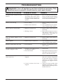
TROUBLESHOOTING
WARNING: Turn off appliance and let cool before servicing. Only
a qualied service person should service and repair heater.
POSSIBLE CAUSE REMEDY
OBSERVED PROBLEM
1. Fireplace has overheated
and safety devise has cause
thermal switch to disconnect
or home circuit breaker has
opened
1. Loose wiring
2. Flame motor defective
1. Bulb(s) are burnt out
2. Wiring is loose
1. Bulb(s) are burnt out
1. Flame motor is defective
1. Low batteries
1. Fireplace is not plugged in to
an electrical outlet
2. Fuse has blown
1. Thermal switch has been
tripped
2. Circuit breaker has been
tripped
Fireplace turns off and will not
turn on
Flame is not moving
Dim or poorly visible ame
Log set and/or ember is not
glowing
Flame sputters
Remote control does not work
Fireplace will not come on when
switch is ipped to ON
Heater does not provide heat
when turned on
1. Reset switch by turning main
power switch off and waiting
5 minutes then turning it back
on or reset circuit breaker
1. Inspect wiring for loose con-
nections
2. Call a qualied service techni-
cian to replace ame motor
1. Inspect bulbs and replace if
necessary
2. Disconnect from power source
and inspect wiring for loose
connections and repair or
replace if necessary
1. Inspect bulbs and replace if
necessary
1. Call a qualied service techni-
cian to replace ame motor
1. Replace AA batteries in re-
mote control
1. Check plug
2. Disconnect from power source
and replace fuse (see Figure 2,
page 3) with F3.15A fuse
1. Turn unit off and unplug
unit for 5 minutes. Plug back
in and turn unit on. If plug
cannot be reached, follow
directions for tripped circuit
breaker
2. Turn off circuit breaker that
supplies electricity to unit.
Wait 5 minutes then ip circuit
breaker back on

www.desatech.com
119624-01A12
6
5
1
2
9
11
10
10
3
4
8
9
7
10
12
10
12
11
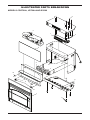
ILLUSTRATED PARTS BREAKDOWN
MODELS CGEF26A, VEF26A AND ES300

www.desatech.com
119624-01A 13
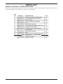
PARTS LIST
MODELS CGEF26A, VEF26A AND ES300
This list contains replaceable parts used in your replace. When ordering parts, follow the instructions
listed under Replacement Parts on page 10 of this manual.
KEY
NO. PART NO. DESCRIPTION QTY.
1 117748-01 Blower and Heater Assembly 1
2 119612-01 Control Board (26" Electric) 1
3 117697-01 Flame Motor 1
4 117749-01 Flame Cylinder Assembly 1
5 119614-01 Log 1
6 117745-01 Rear Glass (Mirror) 1
7 119615-01 Front Face and Glass with Trim 1
8 119613-01 ON/OFF Touch Pad 1
9 119616-01 Hardware Kit: Feet, Screws,
Board Clips
1
10 117754-01 Light Bulb Sockets 4
11 117695-01 Bulb 6
12 117743-01 Screw and Clip (Glass Retainer) 2
PARTS AVAILABLE — NOT SHOWN
117711-01 Remote Control 1
111401-01 Batteries (AA) 2

www.desatech.com
119624-01A14
_____________________________________________________
______________________________________________________
______________________________________________________
______________________________________________________
______________________________________________________
______________________________________________________
______________________________________________________
______________________________________________________
______________________________________________________
______________________________________________________
______________________________________________________
______________________________________________________
______________________________________________________
_____________________________________________________
______________________________________________________
______________________________________________________
______________________________________________________
______________________________________________________
______________________________________________________
______________________________________________________
______________________________________________________
______________________________________________________
NOTES

www.desatech.com
119624-01A 15
_____________________________________________________
______________________________________________________
______________________________________________________
______________________________________________________
______________________________________________________
______________________________________________________
______________________________________________________
______________________________________________________
______________________________________________________
______________________________________________________
______________________________________________________
______________________________________________________
______________________________________________________
_____________________________________________________
______________________________________________________
______________________________________________________
______________________________________________________
______________________________________________________
______________________________________________________
______________________________________________________
______________________________________________________
______________________________________________________
NOTES

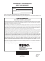
WARRANTY INFORMATION
KEEP THIS WARRANTY
Model
Serial No.
Date Purchased
119624-01
Rev. A
06/06
2701 Industrial Drive
P.O. Box 90004
Bowling Green, KY 42102-9004
www.desatech.com
LIMITED WARRANTY
ELECTRIC FIREPLACE/INSERT
DESA Heating Products warrants this product to be free from defects in materials and components for one (1) year
from the date of rst purchase (excluding bulbs and fuses), provided that the product has been properly installed,
operated and maintained in accordance with all applicable instructions. To make a claim under this warranty the
Bill of Sale or cancelled check must be presented.
This warranty is extended only to the original retail purchaser. This warranty covers the cost of part(s) required
to restore this heater to proper operating condition (excluding bulbs and fuses) and an allowance for labor when
provided by a DESA Heating Products Authorized Service Center. Warranty part(s) MUST be obtained through
authorized dealers of this product and/or DESA Heating Products who will provide original factory replacement
parts. Failure to use original factory replacement parts voids this warranty. The heater MUST be installed by a
qualied installer in accordance with all local codes and instructions furnished with the unit.
This warranty does not apply to parts that are not in original condition because of normal wear and tear or parts that
fail or become damaged as a result of misuse, accidents, lack of proper maintenance or defects caused by improper
installation. Travel, diagnostic cost, labor, transportation and any and all such other costs related to repairing a
defective heater will be the responsibility of the owner. Replacement bulbs are not included in this warranty.
TO THE FULL EXTENT ALLOWED BY THE LAW OF THE JURISDICTION THAT GOVERNS THE SALE
OF THE PRODUCT; THIS EXPRESS WARRANTY EXCLUDES ANY AND ALL OTHER EXPRESSED
WARRANTIES AND LIMITS THE DURATION OF ANY AND ALL IMPLIED WARRANTIES, INCLUDING
WARRANTIES OF MERCHANTABILITY AND FITNESS FOR A PARTICULAR PURPOSE TO ONE (1)
YEAR ON ALL COMPONENTS (EXCLUDING BULBS) FROM THE DATE OF FIRST PURCHASE; AND
DESA HEATING PRODUCTS’ LIABILITY IS HEREBY LIMITED TO THE PURCHASE PRICE OF THE
PRODUCT AND DESA HEATING PRODUCTS SHALL NOT BE LIABLE FOR ANY OTHER DAMAGES
WHATSOEVER INCLUDING INDIRECT, INCIDENTAL OR CONSEQUENTIAL DAMAGES.
Some states do not allow a limitation on how long an implied warranty lasts or an exclusion or limitation of
incidental or consequential damages, so the above limitation on implied warranties or exclusion or limitation on
damages may not apply to you.
This warranty gives you specic legal rights and you may also have other rights that vary from state to state.
For information about this warranty write:
Always specify model and serial numbers when communicating with the factory.
We reserve the right to amend these specications at any time without notice. The only warranty applicable is our
standard written warranty. We make no other warranty, expressed or implied.
NOT A UPC
119624 01
-
 1
1
-
 2
2
-
 3
3
-
 4
4
-
 5
5
-
 6
6
-
 7
7
-
 8
8
-
 9
9
-
 10
10
-
 11
11
-
 12
12
-
 13
13
-
 14
14
-
 15
15
-
 16
16


Desa ES300 Owner's manual
- Category
- Fireplaces
- Type
- Owner's manual
Ask a question and I''ll find the answer in the document
Finding information in a document is now easier with AI
Related papers
-
Desa Tech CGEF21A Owner's manual
-
-
FMI CGEFSO21 Owner's manual
-
Desa Tech CEF26-2 Owner's manual
-
-
-
-
-
Desa CGESBL User manual
-
Other documents
-
Generation Lighting OL5901BK Installation guide
-
Lenoxx LF100 Important Instructions & Operating Manual
-
 Warm House DSF-10302 Installation guide
-
Frigidaire KSF-10301 Installation guide
-
CASAINC TS50 Installation guide
-
 Warm House TZRF-10344 Installation guide
-
-
 MHS Boilers EF500 Installation Instructions Manual
-
-
 EdenPURE PurATron Fireplace FP2011 User manual


