Unique Home Designs 5V0000DN0WH00A Installation guide
- Category
- Garage Door Opener
- Type
- Installation guide
This manual is also suitable for
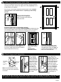
Unique Home Designs 5V0000DN0WH00A is a premium security screen door that provides an additional layer of protection for your home. It features a durable meshtec screen that is both tear-resistant and fire-resistant, ensuring that your home is safe from intruders and pests. The door is also equipped with a heavy-duty lock and reinforced hinges for added security. With its easy installation and low maintenance requirements, the Unique Home Designs 5V0000DN0WH00A is the perfect choice for those looking to enhance the security of their home without sacrificing style or convenience.
Unique Home Designs 5V0000DN0WH00A is a premium security screen door that provides an additional layer of protection for your home. It features a durable meshtec screen that is both tear-resistant and fire-resistant, ensuring that your home is safe from intruders and pests. The door is also equipped with a heavy-duty lock and reinforced hinges for added security. With its easy installation and low maintenance requirements, the Unique Home Designs 5V0000DN0WH00A is the perfect choice for those looking to enhance the security of their home without sacrificing style or convenience.


-
 1
1
-
 2
2
-
 3
3
-
 4
4
-
 5
5
-
 6
6
-
 7
7
-
 8
8
-
 9
9


Unique Home Designs 5V0000DN0WH00A Installation guide
- Category
- Garage Door Opener
- Type
- Installation guide
- This manual is also suitable for
Unique Home Designs 5V0000DN0WH00A is a premium security screen door that provides an additional layer of protection for your home. It features a durable meshtec screen that is both tear-resistant and fire-resistant, ensuring that your home is safe from intruders and pests. The door is also equipped with a heavy-duty lock and reinforced hinges for added security. With its easy installation and low maintenance requirements, the Unique Home Designs 5V0000DN0WH00A is the perfect choice for those looking to enhance the security of their home without sacrificing style or convenience.
Ask a question and I''ll find the answer in the document
Finding information in a document is now easier with AI
Related papers
-
Unique Home Designs 5V0002DN0BZ00B Installation guide
-
-
-
Unique Home Designs 1S2029EL1BKP2A Installation guide
-
Unique Home Designs 5V0000DN2WHGLA Installation guide
-
-
Unique Home Designs SDR06000361150 Installation guide
-
-
-
Other documents
-
MD Building Products 87767 Installation guide
-
Unbranded HD1628S26L Installation guide
-
 Accent Builders Hardware DS-3006SC Installation guide
-
Titan 1S2001DL2CC00A User manual
-
IDEAL Security BKGLMB Installation guide
-
Unbranded 165-SSCHFO-50 Operating instructions
-
Everbilt 165-SCH-FO-40 Installation guide
-
-
Titan 5V0002UL0AL00B Installation guide
-
 Screen Tight GFLAB32 Operating instructions

