Page is loading ...


2 ADS FlowShark HV O&M Manual
© 2010 ADS Environmental Services. All rights reserved.
ADS
®
, ADS Environmental Services
®
, and FlowShark
®
are registered trademarks
of ADS LLC.
All other brand and product names are trademarks or registered trademarks of their
respective holders.
Notice of Proprietary Information
The information contained herein represents the latest information available at the
time of publication. ADS LLC reserves the right to make any changes or
modifications to the content of this document, without notice, to reflect the latest
changes to the equipment. No part of this document may be reproduced in any form
without the written consent of ADS LLC.

ADS FlowShark HV O&M Manual 3
Table of Contents
Introduction ..................................................................................................5
Product Warranty .........................................................................................7
New Product Warranty ...........................................................................7
Out of Warranty Product Repairs ...........................................................7
Troubleshooting Fee ..............................................................................7
Shipping .................................................................................................7
System Overview .........................................................................................9
Operational and Environmental Conditions .........................................10
Setup and Operation ...................................................................................13
Charging the Battery ............................................................................13
Connecting the Sensor to the Control Unit ..........................................14
Operating the FlowShark HV ..............................................................14
Calibrating the Sensor ..........................................................................16
Positioning the Sensor in the Flow ......................................................17
Taking Velocity Readings ....................................................................17
Viewing the Results .............................................................................18
Maintenance ...............................................................................................21
Troubleshooting .........................................................................................23
Technical Specifications ............................................................................25
Control Unit .........................................................................................25
Sensor ...................................................................................................26
CE Guidelines ......................................................................................26


ADS FlowShark HV O&M Manual 5
Introduction
The ADS
®
FlowShark
®
HV (hand-held velocity) is a battery-powered, portable device
designed for taking instantaneous peak flow velocity measurements in wastewater
collection systems, irrigation channels, and streams. The FlowShark HV includes a
control unit, sensor, and battery charger. This manual explains how to setup, operate,
maintain, and troubleshoot the FlowShark HV. It also includes supplemental
information detailing the technical specifications for the equipment. Please read this
manual carefully to ensure proper operation.
Note: When using other components in conjunction with the FlowShark HV,
please consult the component’s accompanying documentation to verify
compatibility with the FlowShark HV.
The manual includes the following sections:
Warranty This section provides comprehensive details concerning product
warranty, repair, and replacement.
System Overview This section offers a brief functional description of the
FlowShark HV system and the operational and environmental conditions
necessary for optimal use.
Setup and Operation This section provides simple instructions on
properly setting up and operating the FlowShark HV for velocity
measurement. It includes general information on charging the battery,
connecting the components, calibrating the sensor, taking velocity
measurements, using the control unit display, and interpreting the results.
Maintenance This section includes basic guidance and instructions for
performing routine maintenance on the FlowShark HV.
Troubleshooting This section provides troubleshooting techniques and
possible solutions for problems that may arise when operating the FlowShark
HV.
Technical Specifications This section lists the technical specifications for
the individual components representing the FlowShark HV. It also includes
some limited certification information.


ADS FlowShark HV O&M Manual 7
Product Warranty
This section includes warranty information for the ADS FlowShark HV.
New Product Warranty
All new products manufactured by ADS will be free from defects in material and
workmanship for up to two (2) years following the date of shipment from ADS.
During this warranty period, upon satisfactory proof of a defect, the product may be
returned for repair or replacement, at ADS’s sole option. No returns will be accepted
unless the Owner has prepaid shipping and has received a prior authorization return
number from ADS. Please contact ADS to obtain an authorization return number.
Warranty repairs and replacements will be performed only by ADS. Any
unauthorized repair or replacement will void this product warranty. Any repair or
replacement will be covered by this new product warranty for ninety (90) days from
the date that such repaired or replaced product is shipped from ADS. This warranty is
available only if the product has been setup and operated in accordance with the
procedures outlined in the ADS Operations and Maintenance Manual. This warranty
does not apply to damage by catastrophes of nature, fire, explosion, acts of God
(including, but not limited to, lightning damage and power surges), accidents,
improper use or service, damage during transportation, or other similar causes beyond
ADS’s control.
Out of Warranty Product Repairs
After the new product warranty expires, a product may be returned, at the owner’s
prepaid expense, to ADS for repair. The owner will pay for all parts and labor
associated with the repair. Any repair part will be covered by the new product
warranty for 90 days from the date of shipment from ADS.
Troubleshooting Fee
ADS will charge a troubleshooting fee if the reported product defect cannot be found
and/or the reported defect is not due to a defect in materials or workmanship.
Shipping
All repaired products will be returned via surface transportation prepaid by ADS.
Import duties, fees, taxes, and other related charges are the responsibility of the
owner.

8 ADS FlowShark HV O&M Manual
THIS IS THE ONLY WARRANTY FOR ADS PRODUCTS. NO OTHER
WARRANTY IS EXPRESSED OR IMPLIED, INCLUDING FITNESS FOR A
PARTICULAR PURPOSE OR MERCHANTABILITY. PRODUCT REPAIR
OR REPLACEMENT IS THE ONLY REMEDY. IN NO EVENT WILL ADS
BE RESPONSIBLE FOR ANY DIRECT, INDIRECT, CONSEQUENTIAL, OR
SPECIAL DAMAGES.

ADS FlowShark HV O&M Manual 9
System Overview
The portable, battery-powered FlowShark HV determines peak flow velocity through
pulse Doppler measurement. A piezoelectric crystal on the sensor transmits
ultrasonic bursts (signals) of a known frequency in rapid succession into the flow for
reflection off existing particles. The FlowShark HV evaluates the echos returned
within a defined time to determine the distances from the sensor to the particles based
on the reflected signals. Analyzing and evaluating the displaced frequencies from the
signals and compensating for the temperature of the flow provides a consistent peak
velocity measurement.
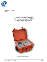
FlowShark HV components – control unit (left) and sensor (right)
Measuring velocity using the Doppler principal requires the presence of scattered
particles, such as air or solid particles, in the flow. To ensure detection, a scattered
particle must be larger than 0.02 inches (0.5 mm) in diameter and occur within flow
containing solids greater than 100 parts per million per volume unit.
v = ∆f
∆f = f
E
- f
S
Where,
∆f = Doppler frequency
f
S
= frequency emitted by sensor
f
E
= frequency displaced by velocity of particles in the flow
C = speed of sound in the flow

10 ADS FlowShark HV O&M Manual
Operational and Environmental Conditions
The technical specifications of the FlowShark HV and the flow and hydraulic
conditions at the measurement location determine the operational success and/or
performance level of the FlowShark HV. Therefore, consider the following
limitations in the hardware and conditions at the location when investigating a
prospective location for performing measurement activities:
Hardware Limitations
Operating Temperature Do not measure velocity at locations exhibiting
temperatures outside the operating temperature range of the sensor.
Relative Humidity The sensor cannot properly measure velocity levels in
the context of relative humidity levels lower than 90% (absence of
condensation).
Electromagnetic Interference The intensity of electromagnetic
interference at the site must not violate the CE guidelines.
Range The sensor cannot measure velocity outside the measurement range
or window designated for the sensor.
Durability The control unit, sensor, and cable contain delicate mechanisms
and electronics. Therefore, handle them with extreme care and avoid stepping
or placing heavy objects on the cable or contacting it with a sharp object. In
addition, the equipment, while durable, is subject to wear, particularly in a
harsh measurement environment. Therefore, conduct routine maintenance on
all components according to the instructions included in the Maintenance
section on page 21. Contact ADS for further information concerning the
durability and limitations of the equipment.
Flow/Hydraulic Limitations
Particulate Size and Reflectivity Measuring velocity using the Doppler
ultrasonic effect involves reflecting emitted signals off particles in the flow.
Smooth, clear flow does not provide objects for reflection and, therefore, is
not the appropriate environment for Doppler measurement. Particles in the
flow, such as air bubbles and solid particles, must be larger than 0.02 inches
(0.5 mm) in diameter and occur in a volume greater than 100 parts per million
for relevant and accurate sensor measurement.
Turbulent/Inconsistent Flow Abnormal or non-uniform flow conditions,
such as turbulence, currents, or reverse flows, adversely affect velocity
measurement. Therefore, do not measure velocity at a location in a pipe or
channel that is in close proximity to these flow conditions.

ADS FlowShark HV O&M Manual 11
Flow Depth Flow levels must exist at a depth of at least 2 to 3 inches (51 to
76 mm) above the bottom center of the pipe or channel to successfully obtain
velocity measurements.
Channel Wall/Water Surface Do not measure velocity within 1.5 inches
(38 mm) of the channel wall or flow surface.


ADS FlowShark HV O&M Manual 13
Setup and Operation
Properly setting up and operating the FlowShark HV are critical to obtaining the most
accurate and reliable velocity measurements. Developing a basic understanding of the
control unit keyboard and display before taking measurements is also essential to
accessing and interpreting the results correctly. These combined skills and knowledge
are fundamental to performing measurement activities effectively and efficiently.
This section provides general information and instructions in the following areas of
setup and operation of the FlowShark HV:
Charging the battery
Connecting the sensor to the control unit
Operating the FlowShark HV
Calibrating the sensor
Positioning the sensor in the flow
Taking velocity readings
Viewing the results
Charging the Battery
Charge the battery before attempting to operate the unit by removing the protective
cap from the corresponding port on the FlowShark HV and connecting the battery
charger to the port. A green light on the charger indicates the battery is fully charged
and the FlowShark HV is ready for use. A yellow light on the charger indicates the
battery in the FlowShark HV is not fully charged, but is being recharged. When
charging is complete, remove the charger and replace the protective cap on the port.
After the initial charge, ADS recommends recharging the battery only once a month
under normal operating conditions. This battery type maintains a longer life and
capacity when recharged less frequently. However, once every 3 months, ADS
recommends draining the battery completely before recharging. The battery is
considered drained at 10.2 volts. The unit will not function when the voltage falls
below 10.
Warning! Close the protective cap manually to avoid damaging the plastic
threads.

14 ADS FlowShark HV O&M Manual
Connecting the Sensor to the Control Unit
Connect the sensor to the control unit by removing the protective cap from the
corresponding port on the unit and then inserting and screwing in the connector from
the sensor cable into the port.
When measurement is complete, unscrew and remove the sensor connector from the
control unit and replace the protective cap onto the port.
Operating the FlowShark HV
Turn on the FlowShark HV by pressing and holding down the Enter key ( ) on the
control unit for at least 5 seconds. The unit temporarily will display the current
firmware version installed and then the current temperature, peak velocity of the flow,
average peak velocity (when initiated manually), and time period over which the
average has been determined. This screen represents the first of three top-level
screens accessible through the control unit.
The second screen displays the battery voltage of the battery in the control unit and
indicates whether the sensor is connected to the control unit. The third screen
displays the signal quality of the measurment, the Doppler frequency, the main peak
velocity, the designated number of neighborhood peaks, and a histogram representing
the measurements taken. Navigate backward and forward among these top level
screens using the horizontal arrow keys (,).
Turn off the control unit by pressing and holding down the ESC key on the unit for at
least 2 seconds. The unit will turn off automatically following 8 minutes of inactivity
on the keyboard.
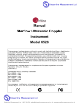
FlowShark HV display

ADS FlowShark HV O&M Manual 15
Modifying the Parameter Settings
The lower level screens provide access to parameter settings that may be modified to
provide additional information, compensate for flow conditions, support associated
hardware, and address other relevant issues involved in velocity measurement
activities. The default parameters are set for the FlowShark HV at the factory. Under
normal conditions, it should not be necessary to access or modify the parameter
settings on the control unit.
Warning! Making changes to the parameter settings requires a
comprehensive understanding of the equipment and settings because it can
have a significant impact on the outcome and accuracy of the velocity
measurements. Therefore, please contact a regional ADS representative for
assistance before setting or modifying any parameters on the FlowShark HV.

16 ADS FlowShark HV O&M Manual
Understanding the Keys on the Control Unit
The following table provides general functional descriptions for the keys on the
control unit. Each key serves multiple functions. The current function of a key
depends on the current content displayed on the control unit screen.
Key
Functional Description
ESC
Turns off the control unit when held down for more than 2 seconds
Returns the menu to the previous level
Turns on the control unit when held down for at least 5 seconds
Displays the parameter settings from the top level
Displays subsettings of parameter settings (when applicable)
Displays current value/option setting corresponding to parameter setting selected
Activates editing mode for bracketed text/values ([xxx])
Deactivates editing mode for bracketed text/values (<xxx>) and saves text/values for
parameter
Scrolls forward through top level screens
Scrolls forward through available parameter settings and subsettings
Moves cursor forward through individual characters in editable field
Scrolls backward through available parameter settings and subsettings
Moves cursor backward through individual characters in editable field
Scrolls forward through individual characters or options in editable field
Scrolls forward through available options for selection in an editable field representing a
particular parameter setting
Scrolls backward through individual characters or options in editable field
Scrolls backward through available options for selection in an editable field representing a
particular parameter setting
Calibrating the Sensor
Before taking velocity measurements, immerse the sensor into the flow to acclimate
the FlowShark HV’s integrated temperature sensor to the temperature of the flow.
Temperature differences between the sensor and flow can produce inaccurate velocity
measurements. A difference of only 1°C can lead to a measurement error of 0.24%.
Acclimation is complete when the temperature reading displayed begins to stabilize
and deviates only within a very limited temperature range of a few degrees.
Temperature and velocity stabilization may require 1 to 5 minutes upon initial use. It
can require several minutes if a large difference exists between the temperature of the
flow and the temperature at the location outside the flow.

ADS FlowShark HV O&M Manual 17
Note: If acclimation and stabilization do not occur within 5 minutes, please
contact an ADS representative for further assistance.
The sensor has been calibrated for measuring velocity in water. However, if velocity
measurements will be taken in another kind of medium in which the speed of sound
differs from that of water (4872 feet per second (1485 mps) at 20°C (68°F)), contact
ADS for assistance in modifying the calibration factor accordingly when setting the
parameters.
Note: Placing the sensor into the flow before turning on the unit may
expedite the temperature acclimation process.
Positioning the Sensor in the Flow
Align the sensor probe parallel to the axis of the pipe/canal. Use the bubble level
attached to the telescoping rod to align the probe horizontally.
Properly positioning the sensor in the flow is essential to obtaining accurate velocity
measurements. Even a slight error in angle can produce errors in velocity readings.
For example, an angle error of 5° will lead to a measurement error of 0.4%; a 10%
angle error will result in a 1.5% measurement error.
Taking Velocity Readings
When immersed in the flow in a pipe or channel, the FlowShark HV measures and
displays the localized, current peak velocity. It also can provide an average, or mean,
of the peak velocity over a specific period of time.
The first (top) row on the control unit display shows the current peak velocity. The
second row displays the current operating temperature read through the temperature
sensor in the probe. Select the up arrow key () to view the current raw frequency
and voltage readings from which the velocity and temperature readings are calculated.
The third row displays the average peak velocity, and the fourth row displays the time
period over which the average peak velocity has been calculated.
Calculating Average (Mean) Peak Velocity
To view the average of the peak velocity over a defined period of time, select the
down arrow key () to initiate the velocity average calculations and then select the
same key again after the desired time period has passed. The FlowShark HV displays
and updates the average velocity following each consecutive reading based on the
cumulative readings taken since the down arrow key was originally selected. The
average velocity displayed represents a “running” average and continues until the
down arrow key is selected again. The last average velocity reading and associated

18 ADS FlowShark HV O&M Manual
time period over which the average was calculated will display until a new running
average velocity is initiated or the control unit display is turned off or goes off
automatically.
ADS also recommends an ISO standard that includes several other methods for
calculating average velocity using the individual velocity measurements obtained
through the FlowShark HV:
ISO 748:2007, Hydrometry – Measurement of Liquid Flow in Open Channels Using
Current-Meters or Floats.
Viewing the Results
A velocity frequency histogram shows the distribution of the Doppler frequencies
emitted. Each bar (peak) represents a frequency group, and up to 11 frequency groups
can display at one time. The frequency range is automatically adjusted to fit the range
of the velocities. The distribution and formation of frequency groups in the histogram
indicate the quality of the velocity readings.
The quality of a measurement (ranging from 0 to 100%) represents the correlation
between the evaluated Doppler frequency and the complete spectrum of the measured
frequencies. Typically, higher quality ratings reflect more reliable velocity
measurements. However, occasionally, a velocity measurement with a relatively high
quality can be unreliable. When a measurement is questionable, examine the form of
the frequency distribution. Velocity measurements with a quality of less than 15%
will be rejected. Consider the following sample histograms for reference in assessing
histograms:
Optimum The following histogram diplays a narrow frequency range with a
stable, very high peak.
--- ---
--- --- --- --- ---
Normal The following histogram reflects a wide frequency range with a
stable, high peak. It has a quality rating greater than 40%.
--- --- ---

ADS FlowShark HV O&M Manual 19
Poor Reflection Quality in Flow The following histogram displays a very
wide range of frequencies with no stable peak, producing a quality rating of
less than 30%. The velocity readings displayed are essentially too low, and
the histogram suggests that the low quality rating may be the result of a low
concentration of reflective particles that are too small for detection. Scattering
or air-injecting reflective particles, such as sand, into the flow for a short time
could improve the histogram and produce more reliable velocity readings.
Refer to the technical specifications for the sensor for specific information on
the minimum particulate size and concentration required for adequate signal
reflection.
--- --- ---
Disturbing Influences The following histogram reveals a wide range of
frequences with a random (jumpy) peak that appears in several frequency
groups. The calculated Doppler frequency (F) jumps significantly. Although
the quality is greater than 40%, the velocity readings are erroneous or unstable
and inconsistent. This histogram could reflect the formation of a whirlpool,
standing waves, a turbulent flow surface, or a very shallow flow depth.
Therefore, a site exhibiting these conditions would not be a suitable location
for obtaining reliable velocity measurements.
--- --- ---

/