Page is loading ...

1
2A9096-010
Hoshizaki Heated Condensate Pan Kit
HS-5453
For Use with the Following Commercial and Steelheart Series:
A. CPT and PR Models: 46, 67, and 93
B. Freezer and Prep Table Models: 48, 60, and 72
Check to ensure that all parts are included:
Index
No. Description
Part
Number Qty
Index
No. Description
Part
Number Qty
1 Heated Condensate Pan 3B0185-01 1 5 Condensate Drain Hose 4A0658L01 1
2 Condensate Pan Bracket 2A9087-01 1 6 Nylon Ties 8911-0200 4
3 Wire Harness Receptacle 4A6049-01 1 7 Bell Connector 8101-14CE 3
4 Self-Drilling Hex Screw 7B03I1210 4 8 Wiring Label 3B0188-01 1
WARNING
• Only qualied service technicians should install and service the appliance to reduce the risk of death, electric
shock, serious injury, or re.
• No installation or service should be undertaken until the technician has thoroughly read these instructions.
Failure to follow these instructions will adversely affect safety, performance, component life and warranty
coverage, and may result in costly water damage.
• See the instruction manual included with the appliance for installation instructions and safety information not
covered in this instruction sheet. If an instruction manual is not available, visit www.hoshizaki.com or contact
your Hoshizaki distributor.
• Appliance is heavy. Use care when lifting or positioning. Work in pairs when needed to prevent injury or
damage.
• To reduce the risk of electric shock, do not touch the plug with damp hands. Unplug the appliance from the
electrical outlet before servicing.
• Protect the oor when moving the appliance to prevent damage to the oor.
• Wear proper personal protection equipment (PPE) when executing these procedures.
A. Installation Instructions for CPT and PR Models
1) On existing models, unplug the appliance from the electrical outlet, then remove all product from the appliance.
2) Move the appliance out to access the rear of the appliance, then lock the casters.
3) On new appliance installation, from the instruction manual, follow and complete all of the installation instructions up to section
"II.E. Door/Drawer Reversal".
4) Remove the front, left side, and rear louver panels. See Fig. 1. Next, remove the current condensate pan and condensate pan
brackets as shown in Fig. 2 and discard, then remove the condensate drain hose. Note: Remove elbow from condensate drain hose
for re-use, then discard condensate hose.
Fig. 1
Rear Louver
Panel
Left Side
Panel
Front Panel
Current
Condensate Pan
Current Condensate
Pan Bracket
Model Shown: PR46A
Fig. 2
Condensate
Drain Hose
Elbow

2
2A9096-010
5) Secure the new condensate pan bracket provided in this kit, with the self-drilling hex screws provided in this kit to the inner wall of
the lower panel. See Fig. 3.
6) Place the new heated condensate pan on the base of the new condensate pan bracket. See Fig. 4.
7) Place the new condensate drain hose over the condensate drain. See Fig. 5. Note: When placing the new condensate drain hose
into position, be sure that the elbow nor the new condensate drain hose make contact with the heater. (Adjust as necessary).
B. Installation Instructions for Freezer and Prep Table Models
1) On existing models, unplug the appliance from the electrical outlet, then remove all product from the appliance.
2) Move the appliance out to access the rear of the appliance, then lock the casters.
3) On new appliance installation, from the instruction manual, follow and complete all of the installation instructions up to section
"II.F. Glass Door Reversal".
4) Remove the rear louver panel. See Fig. 6.
New Condensate
Pan Bracket
Self-Drilling
Hex Screws
Model Shown: PR46A
Fig. 3
New Condensate
Pan Bracket
Inner Wall
Lower Panel
New Heated
Condensate Pan
Fig. 4
Heater
Model Shown: PR46A
Fig. 5
Heater
New Condensate
Drain Hose
Condensate Drain
New Condensate
Drain Hose
Fig. 6
Rear Louver
Panel
Model Shown: UF48A
Note: Make sure
condensate hose
or elbow does not
make contact
with heater.

3
2A9096-010
5) Next, remove the current condensate pan (if applicable) and condensate pan brackets (if applicable), and discard. See Fig. 7.
Specic Instructions for Models: UF48A and WF48A
6) Remove the truss head screw securing the blocking panel to the bottom panel. See Fig. 8. Next, place and level the condensate
pan bracket on the blocking panel, then using the self-drilling hex screws provided in this kit, secure the condensate pan bracket
provided in this kit to the bottom panel as shown in Fig. 9. Note: Verify that the condensate pan bracket is level.
(Adjust as necessary).
Condensate
Pan Bracket
Model Shown: UF48A
Fig. 7
Condensate
Pan
Model Shown: UF60A
Condensate
Pan
Condensate
Drain Hose
Condensate
Drain Hose
Model Shown: UF60A
Fig. 10
Truss Head
Screw
New Condensate
Pan Bracket
Self-Drilling
Hex Screws
Bottom
Panel
Model Shown: UF48A
Bottom
Panel
New Condensate
Pan Bracket
Specic Instructions for Freezer and Prep Table Models (Except UF48A and WF48A Models)
6) Using the self-drilling hex screws, secure the condensate pan bracket to the mounting holes on the bottom panel. See Fig. 10.
Fig. 8 Fig. 9
Blocking
Panel
Bottom
Panel
Self-Drilling
Hex Screws
Blocking
Panel
Mounting
Holes

4
2A9096-010
7) Place the new heated condensate pan on the base of the new condensate pan bracket. See Fig. 11. Note: When placing the heated
condensate pan into position, be sure that the elbow nor the new condensate drain hose make contact with the heater. See Fig. 12.
(Adjust as necessary).
New Condensate
Pan Bracket
Model Shown: UF48A
New Heated
Condensate Pan
Fig. 11
Condensate
Drain Hose
New Heated
Condensate Pan
Condensate
Drain Hose
Heater
Fig. 12
C. Wiring Instructions
If the condensate pan heater wire harness receptacle is already installed skip to step 15. Otherwise, continue to step 8.
8) Locate and remove the folded plastic sleeve to gain access to the wires and bell connectors. See Fig. 13.
Fig. 13
Nylon Tie
Folded Protective Sleeve
Bell Connectors Inside
9) Conrm the appliance is unplugged from the electrical outlet. Next, locate the power supply neutral white (W) wire. Leaving plenty of
slack, cut the power supply neutral white (W) wire.
10) Strip both ends of the power supply neutral white (W) wire cut in step 9 a 1/4" (6.35 mm) back from the ends. Place the wire
harness receptacle provided in this kit, white (W) wire and the 2 power supply neutral white (W) wires just cut and stripped, in a bell
connector provided in this kit, and tighten. See Fig. 14.
11) Next, locate the power supply black (BK) wire. Leaving plenty of slack, cut the power supply black (BK) wire.
12) Strip both ends of the power supply black (BK) wire cut in step 11 a 1/4" (6.35 mm) back from the ends. Place the wire harness
receptacle black (BK) wire and the 2 power supply black (BK) wires just cut and stripped, in a bell connector, and tighten.
Heated
Condensate Pan
Fig. 14
White
(W) Bell
Connector
Black
(BK) Bell
Connector
Appliance
Ground
Wire Harness Receptacle Ground
13) Attach and secure the wire harness receptacle ground green (GR) wire to
the appliance ground screw. See Fig. 15. WARNING! Make sure grounding
wires are attached and secure.
Appliance Grounding Screw
Fig. 15

5
2A9096-010
14) Slide the bell connectors into the protective sleeve removed in step 8, then fold the protective sleeve and secure using a nylon tie
provided in this kit. See Fig. 16.
15) Remove the wire harness receptacle cap, then plug the heated condensate pan power cord into the wire harness receptacle.
See Fig. 17. Secure the heated condensate pan power cord to the appliance main power cord with a nylon tie.
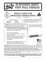
16) Place the wiring label provided in this kit, near the wiring label on the appliance. See Fig. 18. Warning! Conrm that nothing is in
contact with the condensate pan heater.
17) Plug the appliance into the electrical outlet to start the refrigeration process. Do not load product at this time. Warning! Condensate
pan heater is energized and heating up as soon as the appliance is plugged into the electrical outlet. Do not touch.
18) Once plugged in, check the amp draw of the new condensate pan heater.
Note: The condensate pan heater amperage at 115VAC is 2.2A maximum (starting) and 0.3A minimum (A few min. after startup).
19) Replace all panels in their correct positions.
20) Move the appliance back to its correct position.
21) Allow the appliance to cool to set point before putting product back in.
Fig. 16
Nylon Tie
Folded
Protective
Sleeve
Bell Connectors
Inside
Bell Connectors Inside
Folded Protective Sleeve
Wire Harness Receptacle
Cap
Fig. 17
Heated Condensate
Pan Power Supply
Cord
WIRE COLOR CODE
BK BLACK
BR BROWN
BU BLUE
DBU DARK BLUE
GR GREEN
GY GRAY
LBU LIGHT BLUE
O ORANGE
P PINK
R RED
V VIOLET
W WHITE
Y YELLOW
BK/W BLACK/WHITE
CONDENSATE HEATER
3B0115-010
(W)
(BK)
(GR)
CONDENSATE HEATER
POWER CORD
(BK)
(W)
(BK)
(BK)
(GR)
(BK)
(GR)
TO LINE CONNECTION
TO NEUTRAL CONNECTION
This unit has been converted to include a CONDENSATE HEATER.
See the addendum CONDENSATE HEATER wiring schematic below.
HEATER
CONDENSATE HEATER
GND
L
N
115/60/1
WIRE HARNESS
GND
Fig. 18
New
Wiring Label
New
Wiring Label
Current
Wiring Label
Rear
Louver Panel
Model Shown: UF48A
Model Shown: PR46A
Front Panel
Current
Wiring Label
/