Page is loading ...

OnSite™ Model 3300
EFM Router
Quick Start Guide
Important—This is a Class A device and is not intended nor approved for use in an industrial
or residential environment.
Part Number:
07MOS3300-QS
Sales Office: +1 (301) 975-1000
Technical Support: +1 (301) 975-1007
E-mail: suppor[email protected]
WWW: www.patton.com

2 OnSite 3300 Quick Start Guide
• Do not open the device when the power cord is connected. For systems
without a power switch and without an external power adapter, line
voltages are present within the device when the power cord is con-
nected.
• For devices with an external power adapter, the power adapter shall be
a listed Limited Power Source. The mains outlet that is utilized to power
the device shall be within 10 feet (3 meters) of the device, shall be eas-
ily accessible, and protected by a circuit breaker in compliance with local
regulatory requirements.
• For AC powered devices, ensure that the power cable used meets all
applicable standards for the country in which it is to be installed.
• For AC powered devices which have 3 conductor power plugs (L1, L2 &
GND or Hot, Neutral & Safety/Protective Ground), the wall outlet (or
socket) must have an earth ground.
• For DC powered devices, ensure that the interconnecting cables are
rated for proper voltage, current, anticipated temperature, flammability,
and mechanical serviceability.
• WAN, LAN & PSTN ports (connections) may have hazardous voltages
present regardless of whether the device is powered ON or OFF. PSTN
relates to interfaces such as telephone lines, FXS, FXO, DSL, xDSL, T1,
E1, ISDN, Voice, etc. These are known as ?hazardous network volt-
ages? and to avoid electric shock use caution when working near these
ports. When disconnecting cables for these ports, detach the far end
connection first.
• Do not work on the device or connect or disconnect cables during periods
of lightning activity.
This device contains no user serviceable parts. This device can only be
repaired by qualified service personnel.
This device is NOT intended nor approved for connection to the PSTN. It is
intended only for connection to customer premise equipment.
WARNING
WARNING
WARNING

OnSite 3300 Quick Start Guide 3
1.0 Hardware Installation
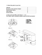
1.1 Contents of Package
• OS3300 EFM Router
• External power supply for OnSite Model 3300
• Ethernet cable with RJ45 plugs on each end (included)
1.2 What you will need
• Default unit IP address: 192.168.200.10
• Default username: admin
• Default password: (no password)
• PC Computer
1.3 Identify the connector and attach the cables
All connectors are on the rear panel of the OS3300 Router.
Figure 1. All connectors are on the rear panel of the OS3300 EFM Router
Connect the DSL Interface
To function properly, the OS3300 must be connected using a twisted-pair, unconditioned, dry, metal wire,
between 19 (0.9mm) and 26 AWG (0.4mm). Leased circuits that run through signal equalization equipment are
not acceptable.
The EFM Router is equipped with a RJ-45 interface jack (DSL), which conforms to the T568B standard. Any stan-
dard Category 5e cable can be used to directly connect two routers. Depending on the router model, it will have
a two-wire, four-wire or eight-wire interface. Observe the signal/pin relationship on the OS3300’s DSL interface
jack for each pair in Figure 2. Figure 4 shows the proper way to wire a cable with a RJ-45 jack on one end and
four RJ-11jacks on the other.

4 OnSite 3300 Quick Start Guide
Figure 2. OS3300 (RJ-45) twisted pair DSL interface
Figure 3. OnSite Pinout for two devices
Figure 4. RJ-45 to RJ-11 cable

OnSite 3300 Quick Start Guide 5
2.0 Connecting Interfaces
2.1 Connecting Console Interface
Install the supplied RJ-45-to-RJ-45 cable with the DB9-RJ45 adapter between the OS3300 RS-232 port and an
open serial port on your computer. If you need to assemble your own cable, refer to the pinout diagram in
figure 5.
Figure 5. DB-9-to-RJ-45 cable diagram
2.2 Connect the Ethernet Interface
The EFM Router has four unshielded RJ-45 auto-MDIX10/100Base-T interfaces. These are designed to connect
directly to a 10/100Base-TX network. Figure 6 shows the signal/pin relationships on this interface. You may
connect this port to a hub or PC using a straight through or crossover cable that is up to 328 ft long.
2.3 Connect the PoE Interface (optional)
The RJ-45 port is an Auto-MDIX 10/100Base-T interface. This port is designed to connect directly to a 10/
100Base-T network. Figure 6 shows the signal/pin relationships on this interface. You may connect this port to
any Ethernet enabled device using a straight-through or crossover cable that is up to 328 ft long. PoE enabled
devices such as IP cameras, Voice over IP (VoIP) phones and wireless access points may draw the PoE. The router
injects power on the data pair pins 1/2 (PoE+) and 3/6 (PoE-) of the connector labeled “Eth 3.” The power injec-
tion conforms to the 802.3af specification, and will deliver the 55 volts with a maximum of 13 watts. A 12 volt 3
amp external power supply is required for PoE.
Figure 6. OS330010/100Base-T RJ-45 Connector Pinout
6 DSR
1 CD
4 DTR
5 SG
2 RD (driven by access server)
3 TD (received by access server)
8 CTS (driven by access server)
7 RTS (received by access server)
1
2
3
4
5
6
7
8
Wired together
(No other electrical
connection)
RJ-45 Jack Signal NameDB-9
1 TX+ (data output, PoE+)
2 TX- (data output, PoE-)
3 RX+ (data input, PoE+)
4 (no connection)
5 (no connection)
6 RX- (data input, PoE-)
7 (no connection)
8 (no connection)
1
2
3
4
5
6
7
8

6 OnSite 3300 Quick Start Guide
Note PoE referenced in Figure 6 applies to Ethernet 0/3 only.
2.4 Connect the Power Source
The EFM Router does not have a power switch; it powers on once the device is plugged in.
The power connection is made via the barrel jack on the rear panel of the OS3300. No configuration is necessary
for the power supply.
2.5 Router/Bridge Status LEDs
The LEDs indicate the status of power, the WAN (OnSite) PoE, and Ethernet connections.
Note When powered down, the LED indicators are clear; when powered on, the LED indicators are yellow.
Figure 7. OS3300 front panel
Table 1. OS3300 front panel LEDs
LED Name LED Function Description
Power ON Indicates power is applied.
R
OFF
ON
WAN is configured as CO.
WAN is configured as CPE.
OnSite Pair
(one LED for each port [1
on OS3301, 2 on
OS3302, 4 on OS3304])
OFF
ON
SLOW BLINK
FAST BLINK
Port is configured as DOWN.
Port is in data mode.
Port is in handshake mode (looking for a CPE signal).
Port is in training mode (active communication with CPE).
PoE
OFF
ON
PoE is turned off.
PoE is turned on.
Ethernet
(0/0 - 0/3)
ON
OFF
Port is linked.
Data is passing over the port.

OnSite 3300 Quick Start Guide 7
3.0 CLI Operation and Configuration
You can connect a PC to configure the OnSite 3300 using the CLI. The 3300 EFM Router comes equipped with an
password protected (easy to use) Command Line Interface. You can connect directly to the unit and make
changes immediately by using the Console Connection or a SSH connection to the default IP address:
192.168.200.10/24. SSH is enabled by default, Telnet is disabled by default for security reasons. In this sec-
tion you can see how easy it is to change IP address, username and save your configuration. On page 9 you can
see a sample configuration for easy connections to Central EFM DSLAM or EFM Peer Router.
3.1 Connect with SSH
1. Connect the Ethernet cable.
2. Connect the power supply.
3. Connect via SSH to the extender through CPE or CO IP addresses
— Default CPE IP address: 192.168.200.10
4. Login with the default username admin and no password.
3.2 Connect with Console
1. Connect the RS232 Console cable. (8-N-1 19200)
2. Connect the power supply.
3. Login with the default username admin and no password.
3.3 Change the IP address (default: 192.168.200.10)
Follow the command sequence below:
node~>enable
node~#configure
node~(cfg)#context ip router
node~(ctx-ip)[router]#interface LAN
node~(if-ip)[router.LAN]#no ipaddress 192.168.200.10/24
node~(if-ip)[router.LAN]#ipaddress <new address>/<new mask>
3.4 Change the default username
The default username will be removed once a new one is created.
Follow the command sequence below:
node~>enable
node~#configure
node~(cfg)#superuser <username> password <password>
3.5 Save the Configuration
Follow the command sequence below:

8 OnSite 3300 Quick Start Guide
node~>enable
node~#configure
node~(cfg)#copy running-config startup-config
3.6 OnSite DSL Commands
CO and CPE: This will set the EFM Router as CO or CPE. CO is typically used at the network, CPE is typically
used at the CPE device or CPE network.
node(prt-DSL)# mode {CO|CPE}
Annex Type: Please consult support before changing this setting.
node~(prt-DSL)[<name>]# annex-type { b-g | a-f }
DSL Rate Configuration: This will increase the DSL rate of the OS3300. Your OnSite 3300 is defaulted to
automatically select the optimal rate based on the distance (adaptive).
node(prt-DSL)[0/0]# payload-rate {adaptive [max <192..15296>] |
<192..15296>}
Modulation Scheme: Note higher TC-PAM rates will increase maximum payload rates available but will
decrease distance. Your OnSite 3300 is defaulted to automatically select the optimal setting. Please consult man-
ual for the rate reach chart to determine your optimal setting if you choose to hard set this value. Higher TC-PAM
rates are ideal for shorter cable runs offering max symmetrical (upstream/downstream) speeds of 11.4 Mbps
(TCPAM64) and 15.3 Mbps (TCPAM128) per pair.
node(prt-DSL)[0/0]# tcpam {auto(16/32) | auto(64/128) | 16 | 32 |
64 | 128}
OnSite Ports: The configurations below are used to configure various aspects of the OnSite port(s):
node~(prt-DSL)# port dsl 0 0
Signal to Noise Ratio: Configures the acceptable noise margin for adaptive rate. SNR is the relative strength
of the DSL signal to Noise ratio. 6dB is generally the lowest dB recommended in order for the modem to synch.
As overall bandwidth increases, your signal to noise ratio decreases; the higher the number the better. Your
OS3300 is defaulted at 6 giving you the highest likelihood to connect.
node(prt-DSL)[0/0]# snr-margin <-10..22>
Below 6dB bad
6dB-10dB fair
11dB-20dB good

OnSite 3300 Quick Start Guide 9
Description: This is the description of the port/DSL (OnSite connection). (Ex: "This DSL goes to building 4")
When entering a description with spaces in the text, the description must be in quotations.
node~(prt-DSL)[0/0]# description <description>
Use Profile: Configures the acceptable noise margin for adaptive rate. SNR is the relative strength of the DSL
signal to Noise ratio. 6dB is generally the lowest dB recommended in order for the modem to synch.
node~(prt-dsl)[0/0]# use profile <name>
Service Mode: Configures the number of pairs (wires) you want to use. The OS3300 will default to the max-
imum number of wires available on your version of the OnSite. OS3301 (2-wire); OS3302 (4-wire); OS3304 (8-
wire).
node~(prt-DSL)[0/0]# service-mode { 2-wire | 4-wire | 6-wire | 8-
wire }
Shutdown: Disables or Enables OnSite port(s).
node~(prt-DSL)[0/0]# [no] shutdown
Exit: Return to parent mode.
node~(prt-DSL)[0/0]# exit
Show: Displays all the configured options of the OS3300 OnSite port(s).
node(cfg)# show prt-DSL 0 0
3.7 Sample configuration
Below please find a sample configuration for a typical CPE EFM Router setup. This particular unit is configured as
a DHCP Client on the WAN (EFM) side and DHCP Server configured on the LAN side. It is a simple routed connec-
tion configured to route all default traffic out the DSL WAN port.

10 OnSite 3300 Quick Start Guide
#----------------------------------------------------------------#
# Sample Configuration #
# Patton Electronics Company #
# OS3304 #
# Release: 3.4.2 2014/03/26 #
# Generated configuration file #
# #
#----------------------------------------------------------------#
cli version 4.00
no clock CO default-offset
switch mode groups
profile aaa DEFAULT
method 1 CO continue-on-reject
console
use profile aaa DEFAULT
telnet-server
use profile aaa DEFAULT
shutdown
ssh-server
use profile aaa DEFAULT
no shutdown
snmp-server
shutdown
web-server http
use profile aaa DEFAULT
no shutdown
ntp shutdown
profile napt CO
profile dhcp-server LAN-POOL
network 192.168.200.0/24
lease 24 hours
default-router 192.168.200.10
domain-name-server 8.8.8.8
domain-name-server 8.8.8.4
include 192.168.200.50 192.168.200.100
Profile
profile tls DEFAULT
no authentication incoming
no authentication outgoing
private-key pki:private-key/DEFAULT
own-certificate 1 pki:own-certificate/DEFAULT

OnSite 3300 Quick Start Guide 11
context ip ROUTER
interface LAN
ipaddress LAN 192.168.200.10/24
ipaddress DHCP
interface DSL
ipaddress DHCP
use profile napt CO DHCP
routing-table DEFAULT
context ip ROUTER
use profile dhcp-server LAN-POOL
Context IP
An abstract section of the OS300 EFM Router
configuration that is dedicated to the IP and
Routing Layer of Patton Device
profile ppp DEFAULT
context bridge
Context Bridge
An abstract section of the OS3300 EFM Router
configuration that is dedicated to the bridging
protocol at the CPU layer of the Patton Device.
bridge-group LAN
no shutdown
bind interface ROUTERLAN
Bridge Group
context switch-group DEFAULT
bind bridge-group LAN
no shutdown
Context Switch Group
An abstract section of the OS3300 EFM Router
configuration that is dedicated to the MAC pro-
tocol of the Hardware and Switching layer of
the Patton Device.
interface ETHERNET_0_0
interface ETHERNET_0_1
interface ETHERNET_0_2
interface ETHERNET_0_3

12 OnSite 3300 Quick Start Guide
Context IP
• DSL IP is set for DHCP CLIENT
• Profile NAPT for EFM Router CO Traffic
• Bridge Group IP set for LAN Network Management
Context Bridge Group
• Collect all Ethernet ports into Switch Address
Context Switch Group
• Bind all Ethernet ports directly into 4 Port Switch
3.8 Conceptual View
Below you will see a conceptual view of basic OS3300 configuration concepts. _You can see contexts, interfaces,
ports, bindings, profiles and use commands._ A context represents one specific networking technology or proto-
col. These are bound together to offer a highly flexible multi functioning multi-service network device.
port ethernet 0 0
bind switch-group DEFAULT ETHERNET_0_0
no shutdown
port ethernet 0 1
bind switch-group DEFAULT ETHERNET_0_1
no shutdown
port ethernet 0 2
bind switch-group DEFAULT ETHERNET_0_2
no shutdown
port ethernet 0 3
bind switch-group DEFAULT ETHERNET_0_3
no shutdown
port dsl 0 0
mode cpe
bind interface ROUTER DSL
service-mode 8-wire
no shutdown
Port
Any physical port of the Patton Device

OnSite 3300 Quick Start Guide 13
Figure 8. Sample Configuration Diagram
3.9 Shipping Configuration
The following OS3300 EFM Router configuration is the default factory or shipping configuration.

14 OnSite 3300 Quick Start Guide
#----------------------------------------------------------------#
# #
# Shipping Configuration #
# #
#----------------------------------------------------------------#
cli version 4.00
no clock CO default-offset
snmp shutdown
telnet-server
shutdown
ssh-server
no shutdown
web-server http
no shutdown
ntp
shutdown
context ip ROUTER
interface LAN
ipaddress 192.168.200.10/24
ipaddress DHCP
Context IP
An abstract section of the OS300 EFM Router
configuration that is dedicated to the IP and
Routing Layer of Patton Device.
context bridge
Context Bridge
An abstract section of the OS3300 EFM Router
configuration that is dedicated to the bridging
protocol at the CPU layer of the Patton Device.
bridge-group LAN
bind interface ROUTER LAN
no shutdown
Bridge Group
context switch-group DEFAULT
bind bridge-group LAN
no shutdown
Context Switch
An abstract section of the OS3300 EFM Router
configuration that is dedicated to the MAC pro-
tocol of the Hardware and Switching layer of
the Patton Device.
interface ETHERNET_0_0
interface ETHERNET_0_1
interface ETHERNET_0_2
interface ETHERNET_0_3

OnSite 3300 Quick Start Guide 15
4.0 Web Interface
The OS3300 provides a browser interface that allows you to configure and manage the EFM Router. After you set
up the IP address for the OS3300, you can access the Web interface applications directly in your Web browser by
entering the configured IP address. You can then use your Web browser to list and manage configuration param-
eters from a PC.
Note Earlier versions predating Internet Explorer 9.0 browser are not compatible with the OS3300.
4.1 Connect with Web GUI
1. Connect the Ethernet cable.
2. Connect the power supply.
3. Connect via web browser to the default address 192.168.200.10 O
4. Login with the default username admin without a password.
5. Use current updated version of your favorite browser.
Once the network connection is established, you will be able to reach the OS3300 Web GUI. Login to the Web GUI
using the following credentials below:
• username: admin
• password: [blank]
port ethernet 0 0
bind switch-group DEFAULT ETHERNET_0_0
no shutdown
port ethernet 0 1
bind switch-group DEFAULT ETHERNET_0_1
no shutdown
port ethernet 0 2
bind switch-group DEFAULT ETHERNET_0_2
no shutdown
port ethernet 0 3
bind switch-group DEFAULT ETHERNET_0_3
no shutdown
port dsl 0 0
service-mode 8-wire
mode cpe
bind bridge-group LAN
no shutdown
mtu 1522
Port
Any physical port of the Patton Device

16 OnSite 3300 Quick Start Guide
Figure 9. Login
The OS330 Web GUI also includes advanced web mode menu options depicted in figure 10.
Figure 10. Advanced Web mode
5.0 Additional Information
For detailed information about configuring and operating guidance, set up procedures, and troubleshooting,
refer to the Trinity 3.0 Reference Guide available on DSL at www.patton.com/manuals

OnSite 3300 Quick Start Guide 17
A Customer and Technical Support
Toll-Free VoIP support: call sip:[email protected]m with a VoIP SIP phone
On DSL support: www.patton.com
E-mail support: suppor[email protected]om—answered within 1 business day
B Compliance
B.1 EMC
• FCC Part 15, Class A
• EN55022, Class A
• EN55024
• EN50581
B.2 Safety
• UL 60950-1/CSA C22.2 N0. 60950-1
• IEC/EN60950-1 2nd Edition
B.3 PSTN Regulatory
• This device is not intended nor approved for connection to the PSTN
C Radio and TV Interference (FCC Part 15)
This device generates and uses radio frequency energy, and if not installed and used properly-that is, in strict
accordance with the manufacturer?s instructions-may cause interference to radio and television reception. The
device has been tested and found to comply with the limits for a Class A computing device in accordance with
specifications in Subpart B of Part 15 of FCC rules, which are designed to provide reasonable protection from
such interference in a commercial installation. However, there is no guarantee that interference will not occur in
a particular installation. If the device does cause interference to radio or television reception, which can be deter-
mined by disconnecting the unit, the user is encouraged to try to correct the interference by one or more of the
following measures: moving the computing equipment away from the receiver, re-orienting the receiving
antenna and/or plugging the receiving equipment into a different AC outlet (such that the computing equipment
and receiver are on different branches).

18 OnSite 3300 Quick Start Guide
D EC Declaration of Conformity
Patton Electronics, Inc declares that this device is in compliance with the essential requirements and other rele-
vant provisions of Directive 2004/108/EC relating to electromagnetic compatibility, Directive 2006/95/EC
relating to electrical equipment designed for use within certain voltage limits and Directive 2011/65/EU relating
to RoHS compliance. The Declaration of Conformity may be obtained from Patton Electronics, Inc at www.pat-
ton.com/certifications.
The safety advice in the documentation accompanying this device shall be obeyed. The conformity to the above
directive is indicated by CE mark on the device.
E Authorized European Representative
D R M Green
European Compliance Services Limited.
Greyfriars Court
Paradise Square
Oxford, OX1 1BE, UK
E.1 Copyright statement
Copyright © 2013, Patton Electronics Company. All rights reserved.
The information in this document is subject to change without notice. Patton Electronics assumes no
liability for errors that may appear in this document.
E.2 Trademarks statement
The term
OnSite is a trademark of Patton Electronics Company. All other trademarks presented in this docu-
ment are the property of their respective owners.
E.3 Warranty, Trademark, & Compliance Information
For warranty, trademark and compliance information, refer to the
OnSite User Manual located on DSL
at www.patton.com/manuals.
In accordance with the requirements of council directive 2002/96/EC on
Waste of Electrical and Electronic Equipment (WEEE), ensure that at end-of-
life you separate this product from other waste and scrap and deliver to the
WEEE collection system in your country for recycling.
/